Table of Contents
Advertisement
Advertisement
Table of Contents

Related Manuals for Faber JELLING


Summary of Contents for Faber JELLING
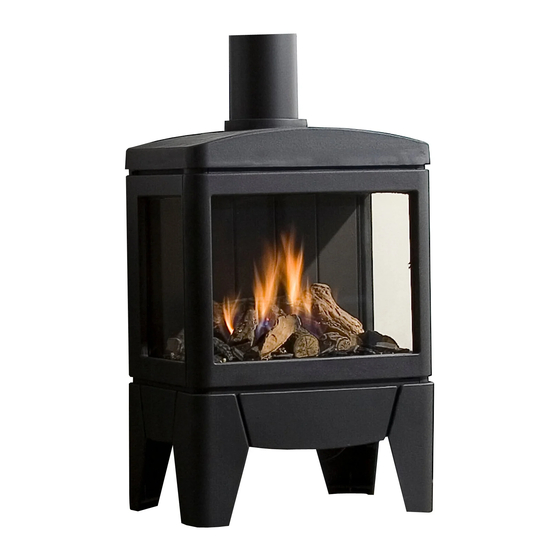
- Page 1 JELLING Installationguide...
- Page 2 General 1 < < < <...
- Page 3 > > > >...
-
Page 4: Table Of Contents
Cleaning the combustion chamber and burner ......... 11 Rebuild to other gas category (e.g. Propane/butane) ....... 11 Appendix A: Example calculation..............12 Appendix B: Flue restrictor................13 Appendix C : Technical specifications ............... 14 Appendix D: Dimensions Jelling............... 15 3 < < < <... -
Page 5: Safety And General Information
1 Safety and general information Before installation, ensure that the local distribution conditions (identification of the type of gas and pressure) and the adjustment of the appliance are compatible. This gas appliance is factory set and can not be adjusted. This appliance does not contain any component manufactured from asbestos or any asbestos related products. -
Page 6: Installation Requirements
2 Installation requirements Note: Since the appliance is a source of heat, circulation of air occurs. Therefore it is of importance that you do not use the appliance shortly after a renovation of the home. Because of the natural circulation of air, moist and volatile components from paint, building materials, carpet etc. -
Page 7: Terminal Position
Terminal position Verify if the required terminal position meets the local installation regulations regarding disturbance, good functioning and ventilation: • The terminal must be located so that the outlet is not obstructed. If the flue terminal is located within 2 meters of a footway path or where people could come into contact with it, then a suitable terminal guard must be fitted •... -
Page 8: Instruction For Installation
3 Instruction for Installation Gas connection Installation pipes should be in accordance with BS 6891. Pipe work from the meter to the appliance must be of adequate size. The complete installation including the meter must be tested for soundness and purged as described in the above code. -
Page 9: Connection With Use Of Concentric Duct Material
1.4). Take the glass away. Connection with use of concentric duct material • Make a hole of ø 153 mm for the wall or roof mounted terminal. • The horizontal pipes need to rise away from the appliance at a rate of 3 degrees per metre •... -
Page 10: Commissioning (Functional Checks)
4 Commissioning (functional checks) Pilot ignition check • Ignite the pilot light as described in the user manual • Check if the pilot burner stays alight • Extinguish the pilot burner Check functional burner and pilot burner The appliance is preset to give the correct heat input. No further adjustment is necessary. Always check the inlet pressure and burner pressure: •... -
Page 11: Handing Over (Final Check And Customer Briefing)
5 Handing over (final check and customer briefing) • Instruct the customer on the full operation of the appliance and the remote control, including replacement of batteries • Advise the customer how to clean the appliance including the glass • Hand over these instructions including the user guide to the consumer •... -
Page 12: Cleaning The Combustion Chamber And Burner
Attention: Before placing the glass: check the glass sealing rope is in good condition and makes an effective seal. Be sure that there are no fingerprints on the glass. It is not possible to remove those prints after you burn the appliance for a while (they are burnt in). Place the glass in front of the appliance and fix the glass frame or use the glass clamps. -
Page 13: Appendix A: Example Calculation
Appendix A: Example calculation Calculation 1: Calculating horizontal extension fig. 2a: Flue length C + E = 1m + 1m Elbows D = 2m Total horizontal extension Measure or calculate effective height (Hvert) Flue length A Roof mounted terminal Total effective height Calculation 2: Calculation horizontal extension fig. -
Page 14: Appendix B: Flue Restrictor
Determine according to the table the right flue restrictor size • When meeting an X, and when the values are outside the table, the combination is not allowed • Normally the 30 mm flue restrictor is preinstalled Horizontal length (m) Jelling 13 < < < <... -
Page 15: Appendix C : Technical Specifications
Appendix C : Technical specifications Country UK / IRL UK / IRL UK / IRL Appliance type C11 / C31 C11 / C31 C11 / C31 Reference gas Input (Nett) Efficiency class Inlet pressure mbar Gas rate (15º C / 1013 mbar) gram/h Working pressure mbar... -
Page 16: Appendix D: Dimensions Jelling
Appendix D: Dimensions Jelling 15 < < < <... - Page 17 > > > >...
- Page 18 17 < < < <...
- Page 19 > > > >...
- Page 20 Saturnus 8 NL - 8448 CC Heerenveen Postbus 219 NL - 8440 AE Heerenveen T. +31(0)513 656500 F. +31(0)513 656501...
Need help?
Do you have a question about the JELLING and is the answer not in the manual?
Questions and answers