Advertisement
Quick Links
Advertisement

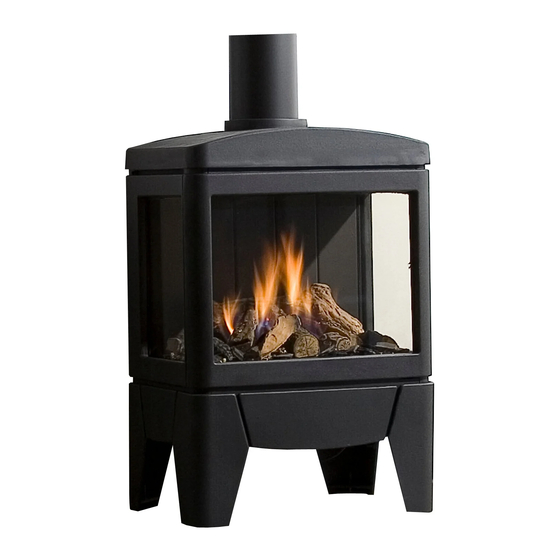
Summary of Contents for Faber Jelling
- Page 1 Installation manual Jelling 40010705-2010...
- Page 2 Installation manual Jelling 1 < < < <...
- Page 3 Installation manual Jelling 2 < < < <...
- Page 4 Installation manual Jelling 1.3a 1.3b 3 < < < <...
- Page 5 Installation manual Jelling 4 < < < <...
- Page 6 Installation manual Jelling 5 < < < <...
- Page 7 Installation manual Jelling Dear user Safety instructions Congratulations on your purchase of a Faber fire! A Please note! quality product from which you will experience warmth and atmosphere for many years. We It is advisable to always install a screen for the...
-
Page 8: Installation Requirements
C31, outlet via roof See fig. 1.3a for the wiring diagram: For a (flat) roof, use a Faber roof outlet with a A = Adapter (6 V) diameter of 100/150mm. B = Gas valve... - Page 9 For replacing the glass repeat the steps in reverse The controller can be connected to an external order. source, such as a Domotica system, by using a Faber Interface Unit (article number A9323000). Please note! Avoid fingerprints on the glass, these are no 4.4 Preparing the fireplace longer removable once the fire is used.
- Page 10 Installation manual Jelling Assess whether the flame distribution is The pipe connections for leaks. good. Move or remove any ash material to (in case of blue flames); create a nice glow bed. That the correct flue restrictor is fitted ...
- Page 11 Start length (STL): Remove the front glass (see chapter 5). The first part that is placed on the You can clean the glass with Faber glass polish. fireplace and represents a certain value This is a specially formulated cleaning agent that (fig.
- Page 12 Installation manual Jelling In case of an “X” or if the values are outside the The value found indicates the width of the flue restrictor table, the combination is not permitted. restrictor to be placed (“0” means no flue Then adjust TVH or THL.
- Page 13 Installation manual Jelling 11.1 Restrictor table (100/150) Start length (STL) Vertical (TVH) and Horizontal (THL) 30.00 0.00 0.00 30.00 30.00 0.00 0.00 0.00 30.00 30.00 30.00 0.00 0.00 0.00 0.00 40.00 30.00 30.00 30.00 0.00 0.00 0.00 40.00 40.00 30.00 30.00...
- Page 14 Installation manual Jelling 12 Examples flue materials 13 < < < <...
- Page 15 Installation manual Jelling 13 Calculation sheet Starter length (STL) First part on top of the appliance Value Flue length from 0,1m till 0,45m Flue length from 0,5m till 0,90m Flue length from 1m till 1,4m Flue length from 1,5m till 2m Flue length 2m or more Bend 90°...
- Page 16 Installation manual Jelling found value Search in the table at TVH and THL and enter the value that is found. ……………………………… If the detected value is a number, check whether the completed STL is higher or equal to the value in the table.
-
Page 17: Technical Data
Installation manual Jelling 14 Technical data Technical data Type indication(s) Jelling Type appliance C11/C31/C91 Diameter outlet/inlet 100/150 Gas connection 3/8" Indirect heating functionality Category II2H3+ Symbol Unit Reference gas/inlet pressure G20-20 G30-30 G31-37 mbar Emissions in space heating mg/kWh (GVC) - Page 18 Installation manual Jelling 15 Outlet position Please note! These rules apply only for the proper functioning of the unit, for ventilation and environmental protection you need to comply with the applicable rules as defined in the building regulations. Short roof terminal.
-
Page 19: Troubleshooting Guide
Installation manual Jelling 16 Troubleshooting guide 18 < < < <... - Page 20 Installation manual Jelling 19 < < < <...
- Page 21 Installation manual Jelling 17 Dimensional drawings 17.1 Jelling 20 < < < <...
- Page 22 Installation manual Jelling 17.2 Position gas connection 21 < < < <...
- Page 23 Installation manual Jelling 18 Decoration instruction card 22 < < < <...
- Page 24 Installation manual Jelling 23 < < < <...
- Page 25 Installation manual Jelling 24 < < < <...
- Page 26 Installation manual Jelling 25 < < < <...
- Page 27 Installation manual Jelling 26 < < < <...
- Page 28 www.faberfires.com contact@faberfires.com Saturnus 8 NL 8448 CC Heerenveen Postbus 219 NL 8440 AE Heerenveen...


Need help?
Do you have a question about the Jelling and is the answer not in the manual?
Questions and answers