Table of Contents
Advertisement
www.proform.com
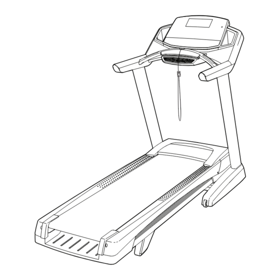
Model No. PFTL11012.0
Serial No.
Write the serial number in the space
above for reference.
Serial Number
Decal
QUESTIONS?
If you have questions, or if parts
are damaged or missing, DO NOT
CONTACT THE STORE; please
contact Customer Care.
IMPORTANT: Please register this
product (see the limited warranty
on the back cover of this manual)
before contacting Customer Care.
CALL TOLL-FREE:
1-888-533-1333
Mon.––Fri. 6 a.m.––6 p.m. MT
Sat. 8 a.m.––4 p.m. MT
ON THE WEB:
www.proformservice.com
CAUTION
Read all precautions and instruc-
tions in this manual before using
this equipment. Save this manual
for future reference.
USER’'S MANUAL
Advertisement
Table of Contents

Related Manuals for Pro-Form PFTL11012.0


Summary of Contents for Pro-Form PFTL11012.0
- Page 1 Model No. PFTL11012.0 USER’’S MANUAL Serial No. Write the serial number in the space above for reference. Serial Number Decal QUESTIONS? If you have questions, or if parts are damaged or missing, DO NOT CONTACT THE STORE; please contact Customer Care.
-
Page 2: Table Of Contents
TABLE OF CONTENTS WARNING DECAL PLACEMENT ............. . . 2 IMPORTANT PRECAUTIONS . -
Page 3: Important Precautions
IMPORTANT PRECAUTIONS WARNING: To reduce the risk of burns, fire, electric shock, or injury to persons, read all important precautions and instructions in this manual and all warnings on your treadmill before using your treadmill. ICON assumes no responsibility for personal injury or property damage sus- tained by or through the use of this product. - Page 4 20. The heart rate monitor is not a medical 24. Do not change the incline of the treadmill by device. Various factors, including the user’’s placing objects under the treadmill. movement, may affect the accuracy of heart rate readings. The heart rate monitor is 25.
-
Page 5: Before You Begin
BEFORE YOU BEGIN Thank you for selecting the revolutionary PROFORM reading this manual, please see the front cover of this ® POWER 1080 i treadmill. The POWER 1080 i treadmill manual. To help us assist you, please note the product offers an impressive selection of features designed model number and serial number before contacting us. -
Page 6: Part Identification Chart
PART IDENTIFICATION CHART Use the drawings below to identify small parts used for assembly. The number in parentheses below each draw- ing is the key number of the part, from the PART LIST near the end of this manual. The number following the key number is the quantity used for assembly. -
Page 7: Assembly
ASSEMBLY •• To hire a service technician to assemble this •• Left parts are marked ““L”” or ““Left”” and right parts product in your home, call 1-800-445-2480. are marked ““R”” or ““Right.”” •• Assembly requires two persons. •• To identify small parts, see page 6. ••... - Page 8 2. Pull the Upright Wire (78) and the base ground wire (A) through the indicated hole in the Base (95). If there is a screw (B) preinstalled in the side of the Base (95), remove and discard it. Attach Hole the ground wire (A) to the Base with a #8 x 1/2"...
- Page 9 4. Hold the Left Upright (79) against the Base (95). Make sure not to pinch the Upright Wire (78). Insert two 3/8" x 1 1/4" Screws (6) with two 3/8" Star Washers (13) and two 3/8" x 2 3/4" Screws (5) into the Left Upright.
- Page 10 6. Attach the Left Handrail (83) to the Left Upright (79) with two 5/16" x 2 1/2" Screws (10) and two 5/16" Star Washers (11). Make sure that the Upright Wire (78) is resting in the slot as shown and is not pinched. Fully tighten the Slot Screws.
- Page 11 8. Set the console assembly face down on a soft surface to avoid scratching the console assem- bly. Remove and discard the three screws (D). Then, lift off the Console Cover (100). Console Assembly 9. Set the console assembly on the Left Handrail Console (83) and the Right Handrail (86).
- Page 12 10. Attach the console assembly to the Handrails (83, 86) with four #10 x 3/4" Screws (7) and four Console #10 Star Washers (14) as shown. Start all four Assembly Screws, and then tighten them. 11. Connect the Upright Wire (78) to the console wire (E).
- Page 13 12. Attach the Left Handrail Cover (82) and the Right Handrail Cover (85) to the Handrails (83, 86) with three #8 x 1/2" Screws (1) each. Do not over- tighten the Screws. 13. Slide the Left Bottom Handrail Cover (84) up against the Left Handrail Cover (82).
- Page 14 15. Firmly tighten the four 3/8" x 2 3/4" Screws (5) and then the four 3/8" x 1 1/4" Screws (6) (only one side is shown). Press the Left Base Cover (81) and the Right Base Cover (89) onto the Base (95) until they snap into place.
-
Page 15: The Chest Heart Rate Monitor
THE CHEST HEART RATE MONITOR HOW TO PUT ON THE HEART RATE MONITOR •• Do not expose the heart rate monitor to direct sun- light for extended periods of time; do not expose it The heart rate to temperatures above 122° F (50° C) or below 14° monitor consists of F (-10°... -
Page 16: Operation And Adjustment
OPERATION AND ADJUSTMENT HOW TO CONNECT THE POWER CORD nominal 120-volt circuit capable of carrying 15 or more amps. To avoid overloading the circuit, do Use a Surge Suppressor not plug other electrical devices, except for low- power devices such as cell phone chargers, into Your treadmill, like other electronic equipment, can be the surge suppressor or into an outlet on the same damaged by sudden voltage changes in your home’’s... - Page 17 CONSOLE DIAGRAM FEATURES OF THE CONSOLE To turn on the power, see page 18. To use the man- The treadmill console offers an impressive array of ual mode, see page 18. To use an onboard workout, features designed to make your workouts more effec- see page 21.
-
Page 18: To Use Manual Mode
HOW TO TURN ON THE POWER HOW TO USE THE MANUAL MODE IMPORTANT: If the treadmill has been exposed to 1. Insert the key into the console. cold temperatures, allow it to warm to room tem- perature before turning on the power. If you do not See HOW TO TURN ON THE POWER at the left. - Page 19 4. Change the incline of the treadmill as desired. The My Trail tab will show a track that represents 1/4 mile (400 m). As you exercise, the ashing To change the incline of the treadmill, press the rectangle will show your progress. The My Trail tab Incline increase or decrease button or one of the will also show the number of laps you complete.
- Page 20 6. Measure your heart rate if desired. 7. Turn on the fan if desired. Note: If you use the handgrip heart rate moni- The fan features mul- tor and the chest heart rate monitor at the same tiple speed settings. Increase time, the console will not display your heart Press the fan increase...
-
Page 21: How To Use Onboard Workout
HOW TO USE AN ONBOARD WORKOUT The workout will continue in this way until the last segment of the pro le ashes in the display and the 1. Insert the key into the console. last segment ends. The walking belt will then slow to a stop. - Page 22 HOW TO USE A SET-A-GOAL WORKOUT The workout will continue until you reach the goal that you set. The walking belt will then slow to a 1. Insert the key into the console. stop. See HOW TO TURN ON THE POWER on page 18. Note: The calorie goal is an estimate of the number of calories that you will burn during the 2.
- Page 23 HOW TO USE AN IFIT WORKOUT 5. Start the workout. Note: To use an iFit workout, you must have access See step 3 on page 21. to a wireless network (see page 25). An iFit account is also required. Go to www.iFit.com to register for an During some workouts, the voice of a personal iFit account.
- Page 24 HOW TO USE THE STEREO SOUND SYSTEM Next, press the play button on your MP3 player, CD Decrease To play music or audio books through the console’’s player, or other personal stereo speakers, you must connect your MP3 player, audio player. Adjust the vol- CD player, or other personal audio player to the con- ume on your personal audio sole through the audio jack.
- Page 25 HOW TO CHANGE CONSOLE SETTINGS Default Menu——The default menu will appear when you insert the key into the console or when you The console features a settings mode that allows you press the Home button. Press the Enter button to view usage information, to personalize console set- repeatedly to select the manual main screen or the tings, and to set up and manage a wireless network iFit screen as the default menu.
- Page 26 Clear WiFi Setting——To erase the console’’s Press the up, down, left, and right buttons to high- wireless network settings and have it forget the light the desired letter or number. Then, press the currently selected wireless network, follow the Enter button to select the letter, number, or symbol. instructions in the matrix.
- Page 27 6. Use WiFi––Advanced to set up a wireless Your browser will load a web page. If the web page connection. does not appear, double-check the IP address and the previous instructions of this step. Follow the This option will allow you to set up a wireless instructions on the web page to connect the tread- network connection using your computer, smart mill to your wireless network.
-
Page 28: How To Fold And Move The Treadmill
HOW TO FOLD AND MOVE THE TREADMILL HOW TO FOLD THE TREADMILL HOW TO MOVE THE TREADMILL To avoid damaging the treadmill, adjust the incline Before moving the treadmill, fold it as described at the to the lowest position before you fold the treadmill. left. -
Page 29: Troubleshooting
TROUBLESHOOTING Most treadmill problems can be solved by follow- c. Remove the key from the console, and then ing the simple steps below. Find the symptom that reinsert it. applies, and follow the steps listed. If further assis- tance is needed, see the front cover of this manual. d. - Page 30 Locate the Reed Switch (52) and the Magnet (53) b. If the walking belt is overtightened, treadmill per- on the left side of the Pulley (54). Turn the Pulley formance may decrease and the walking belt may until the Magnet is aligned with the Reed Switch. become damaged.
- Page 31 SYMPTOM: The walking belt is off-center or slips b. If the walking belt slips when walked on, first when walked on remove the key and UNPLUG THE POWER CORD. Using the hex key, turn both idler roller a. If the walking belt is off-center, first remove the screws clockwise, 1/4 of a turn.
-
Page 32: Exercise Guidelines
EXERCISE GUIDELINES Burning Fat——To burn fat effectively, you must exer- WARNING: cise at a low intensity level for a sustained period of Before beginning this time. During the first few minutes of exercise, your or any exercise program, consult your physi- body uses carbohydrate calories for energy. - Page 33 SUGGESTED STRETCHES The correct form for several basic stretches is shown at the right. Move slowly as you stretch ——never bounce. 1. Toe Touch Stretch Stand with your knees bent slightly and slowly bend forward from your hips. Allow your back and shoulders to relax as you reach down toward your toes as far as possible.
-
Page 34: Part List
PART LIST Model No. PFTL11012.0 R1012B Key No. Qty. Description Key No. Qty. Description #8 x 1/2" Screw Reed Switch Clip #8 x 3/4" Screw Reed Switch 3/8" x 2" Bolt Magnet 3/8" x 1 3/4" Bolt Idler Roller/Pulley 3/8" x 2 3/4" Screw Cable Tie 3/8"... - Page 35 Key No. Qty. Description Key No. Qty. Description Console Fan Cover Left Tray Fan Grill Right Tray Incline Motor Spacer Console Base Chest Strap Console Trim Sensor Pulse Bar –– User’’s Manual Pulse Bar Bottom Note: Specifications are subject to change without notice. For information about ordering replacement parts, see the back cover of this manual.
-
Page 36: Exploded Drawing
EXPLODED DRAWING A Model No. PFTL11012.0 R1012B... - Page 37 EXPLODED DRAWING B Model No. PFTL11012.0 R1012B...
- Page 38 EXPLODED DRAWING C Model No. PFTL11012.0 R1012B...
- Page 39 EXPLODED DRAWING D Model No. PFTL11012.0 R1012B...
-
Page 40: Ordering Replacement Parts
ORDERING REPLACEMENT PARTS To order replacement parts, please see the front cover of this manual. To help us assist you, be prepared to pro- vide the following information when contacting us: •• the model number and serial number of the product (see the front cover of this manual) ••...
Need help?
Do you have a question about the PFTL11012.0 and is the answer not in the manual?
Questions and answers