
Subscribe to Our Youtube Channel
Related Manuals for Teac LX-100 Series


Summary of Contents for Teac LX-100 Series
- Page 1 RECORDING UNIT LX-100 Series Instruction Manual Please read this manual before using the product and keep the manual handy. TEAC Corporation Oct. 2007 D00986400A...
-
Page 2: Safety Instructions
SAFETY INSTRUCTIONS CAUTION: Read all of these Instructions. Save these Instructions for later use. Follow all Warnings and Instructions marked on the product. 1) Read instructions -- All the safety and operating instructions should be read before the product is operated. 2) Retain instructions -- The safety and operating instructions should be retained for future reference. - Page 3 SAFETY INSTRUCTIONS 17) Damage Requiring Service -- Unplug this product from the wall outlet and refer servicing to qualified service personnel under the following conditions: a) when the power-supply cord or plug is damaged. b) if liquid has been spilled, or objects have fallen into the product. c) if the product has been exposed to rain or water.
- Page 4 Wohnbereich Funkstörungen versursachen ; in diesem Fall kann vom Betrieber verlang werden, angemessene Maßnahmen durchzuführen und dafür aufzukommen. DISCLAIMER TEAC disclaims all warranty, either expressed or implied, with respect to this product and the accompanying written materials. In no event shall TEAC be liable for any damages whatsoever (including, without limitation, damages for loss of business profits, business interruption, loss of business information or other loss) arising out of the use of or inability to use this product.
- Page 5 2. COPYRIGHT All title and copyrights in and to the SOFTWARE and any copies thereof are owned by TEAC or a supplier to TEAC. The SOFTWARE is protected by Japanese copyright laws, international treaty provisions, and all other applicable national laws.
-
Page 6: Table Of Contents
Section 2 Installation ........................1 Connections................................ 2 Notes of Connections ..........................3 PC Requirements ............................3 Installing LX-100 Series (IEEE 1394 model)....................... 4 Installing Interface Card..........................4 Installing OHCI Driver..........................5 Install LX-100 Series Device Driver......................6 Download the 1394 Storage Supplement Program ..................8 Installing LX Navi............................ -
Page 7: Index
Index Moving Reproducing Point (Skip) ......................14 Advanced search............................15 Convenient Features............................16 Displaying Waveform..........................16 Channel Property ............................. 17 Displaying Bar Meter ..........................18 Displaying Digital Values .......................... 18 Viewing Header Information ........................18 Changing Modes ............................20 Stopping Fan ............................21 Listening to Data by Sound ........................ -
Page 9: Section 1 Preface
Section 1 Preface... -
Page 10: Overview
Recording to the internal memory or to a PC card. Also, you can save the recorded data as PC files by connecting to a PC. The file format is TEAC's proprietary TAFFmat format. TAFFmat files can be loaded into commercially available analysis software. -
Page 11: Features
Features Features ■ Input/Output Amps The LX main unit is equipped with two slots and the optional expansion unit provides an additional two slots for installing the input amps and/or the output amps. The input/output amp provides 8-channel inputs/outputs from the selections below. DC input amp card: Use to connect voltages and/or to connect signals of external amplifiers. - Page 12 Features ■ Event Marks You can mark the data during recording. Then you can search for such event marks when you want to reproduce some recorded data. ■ Recording and Reproducing Voice Memos A microphone amp and a speaker are built in so that you can record and reproduce (listen to) voice memos. ■...
-
Page 13: About Taffmat
.., last sampling channel order. In LX-100 series, ±100% of the input range is equivalent to ±25000 of 16 bits A/D or ±6400000 of 24 bits A/D This document uses the term “scan”... -
Page 14: Notes On Usage
Use an optional battery unit to back up the operation on power stoppages. Use Specified Media Only Use PC cards checked by TEAC in advance (contact us for information). Other media might be unable to record or reproduce correctly. Compact Flash Cards Checked by TEAC for Correct Operations (as of July 2007) SanDisk Corp. - Page 15 Notes on Usage ■ Handling PC Card To discharge static electricity from your body, touch a metallic surface near you before handling the unit. Never touch the PC card being inserted into the PC card slot while recording and playing back. ■...
-
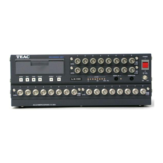
Page 16: Names And Parts
Names and Parts Names and Parts Front Drive Opening the cover reveals the disk slot. Input level LED When the input signal for a channel is larger than +/- 10 % of a set input range, the LED glows green. When the signal exceeds +/- 115 % of the range, the LED glows red. - Page 17 Names and Parts Output connector (When the analog playback amp card is installed in the slot.) Outputs the reproduced signal. Outputs the input signal during recording-standby status or during recording. You can set the output range in 0.1 V steps, from 1 V to 5 V. Output level LED (When the analog playback amp card is installed in the slot.) When the output signal for a channel is larger than +/-10% of a set output range, the LED glows green.
-
Page 18: Rear
Names and Parts Rear LX-110 IEEE 1394 Version LX-110 RECORDING UNIT 12-28V 6.0-2.6A BATTERY UNIT:BU-81 TEAC CORPORATION SERIAL NO. MADE IN JAPAN The LX-110LAN model has an interface (at 7) shown below. LX-120 LAN Model LX-120 RECORDING UNIT 12-28V 6.5-2.8A... - Page 19 Names and Parts FG terminal Connects the grounding wire. MON OUT connector Outputs in analog format the signal of a channel during recording-standby status, recording, or reproduction. You use the supplied LX Navi software to select the channel you want to monitor. You can set the output range in 0.1 V steps, from 1 V to 5 V.
-
Page 20: Recording Time
Recording time Recording time ■ Recording to Memory, 8 channels, 16 bits A/D, 64 MB standard memory (when not recording voice memos) Sampling frequency ( Value in brackets is the recording Recording time bandwidth with tolerances of +/-0.5 dB) (40 kHz) 96 kHz 40 sec (20 kHz)... -
Page 21: Sampling Frequency And Number Of Channels
Sampling Frequency and Number of Channels Sampling Frequency and Number of Channels A combination of the sampling frequency vs. the number of analog input channels varies depending on the selected recording mode (e.g., the type of the recording media, the number of tachometer input channels, etc.). - Page 22 Sampling Frequency and Number of Channels (16bitsAD/24bitsAD) 65.536kHz series Max. number of analog input channels based on the tachometer input setting Sampling Frequency(kHz) Bandwidth (kHz) 16bits 2ch 32bits 1ch 32bits 2ch *65.536 2/Unrecordable 2/Unrecordable Unrecordable *32.768 4/Unrecordable 16.384 16/8 8/Unrecordable 8.192 32/16 24/Unrecordable...
- Page 23 Sampling Frequency and Number of Channels Recording Condition 2 Recording Mode: Recording to the internal memory or direct recording to the PC Memo Voice Recording: ON or OFF Interface to PC: IEEE1394 or LAN 102.4kHz series Max. number of analog input channels based on the tachometer input setting Sampling Frequency(kHz) Bandwidth (kHz) 16bits 2ch 32bits 1ch...
- Page 24 Sampling Frequency and Number of Channels Remarks: Cannot select the moving average other than 1 (one) at the Sampling Frequency settings shown with *(asterisk). In 24 bits A/D, 2ch (16 bits) of tachometer input is not available. When using LAN as the main unit interface and PC direct recording, continuous recording operations might not be possible (it might be stopped while recording because all memory has been used) on setting the maximum number of recording channels.
-
Page 25: Section 2 Installation
Section 2 Installation... -
Page 26: Connections
Oscilloscope, etc. BU-81 Or use the specified AC adaptor Tachometer Pulse Inputs(LX-120 only) LX-120 RECORDING UNIT 12-28V 6.5-2.8A BATTERY UNIT:BU-81 TEAC CORPORATION SERIAL NO. MADE IN JAPAN Remote Control Connectors for Unit Connect to PC 100BASE-TX LAN AQ-VU Sync. Cannot connect... -
Page 27: Notes Of Connections
Connections Notes of Connections ■Attaching Ferrite Core on IEEE 1394 Interface cable (IEEE 1394 model) To reduce the radio noise, attach the supplied ferrite cores on both ends of the IEEE 1394 cable. ■ IEEE1394 connector is available for PC only (IEEE1394 model) Do not connect devices other than the PC to the IEEE 1394 connector. -
Page 28: Installing Lx-100 Series (Ieee 1394 Model)
1. Attach the interface card to your PC. 2. Install the OHCI driver. 3. Install the LX-100 Series device driver. 4. Install the LX Navi. Installing Interface Card Attach the PC card to your note PC Insert the IEEE 1394 interface card CBFW3 to your PC card slot met the CardBus specification. -
Page 29: Installing Ohci Driver
Installing LX-100 Series (IEEE 1394 model) Installing OHCI Driver The following screen samples are for Windows XP. However, these operations are helpful for Windows 2000. Insert the CBFW3 in the CardBus PC card slot, or insert the PCIFW3 and then turn on your PC. The standard Windows driver will be automatically installed. -
Page 30: Install Lx-100 Series Device Driver
Double click [1394Bus host Controllers], and confirm that “Texas Instruments OHCI Compliant IEEE 1394 Host Controller” is added to indicate that the driver software has been correctly installed. Now the OHCI driver installation has been completed. Next proceed to the LX-100 Series device driver installation. - Page 31 Installing LX-100 Series (IEEE 1394 model) Select “Search for the best driver in these locations” and “Include this location in the search:” Enter the file path of the CD-ROM drive in the combo-box ( “D:¥Driver” in the example above) and click [Next] to proceed.
-
Page 32: Download The 1394 Storage Supplement Program
Installing LX-100 Series (IEEE 1394 model) Download the 1394 Storage Supplement Program From the Microsoft site, download the 1394 Storage Supplement program. This program will fix the problem of the 1394 storage device (using transfer rate of S400) not operating according to the supposed specification. - Page 33 Installing LX-100 Series (IEEE 1394 model) The Following Download Center site for the Microsoft Windows XP update program (KB885222) will be displayed. Press the “Continue” button to begin installation of the program according to the contents of the Microsoft Windows XP update program. (The above screen was taken from the Microsoft web site of September, 2007.) This update program (KB885222) cannot be installed by Microsoft auto-update.
-
Page 34: Installing Lx Navi
Installing LX-100 Series (IEEE 1394 model) Installing LX Navi To install the supplied LX Navi software: Execute “Setup.exe”, which is in the supplied CD-ROM. Follow the instructions displayed and proceed with the setup. Click IEEE1394 at the dialog box that will appear in the middle of the installation when using IEEE 1394 model and, then, click OK. -
Page 35: Installing Lx-100 Series (Lan Model)
Installing LX Navi To install the LX Navi software supplied: Set the supplied CD-ROM to CD/DVD drive. The program installation of the LX-100 Series will start to run. If the program will not run, execute “Setup.exe” in the CD-ROM. Follow the instructions displayed and proceed with setup. -
Page 36: About Ip Address Settings
■ The default settings of the LX-100 Series are as follows. Modify the settings (such as the IP address) as necessary. How to change: Click the portion of the IP address in LX Network dialogue to display LX Property dialogue. -
Page 37: Starting Program
Windows power options is not selected. Note that some notebook PCs automatically go into sleep mode just by folding the display. For LX-100 Series (IEEE 1394 model) Check the box at the serial field of the LX Network dialog box by confirming that the correct serial number is displayed, and then click OK. - Page 38 If the whiteout box has not appeared, follow the next pages for a proper set up. The upper part lists the LX-100 series that exist in the same segment. If you click where the IP address or the name is displayed in the list area, the LX Property dialog box will appear. In this dialog box, you specify settings, such as the IP address parameters and the recorder name (Name).
- Page 39 Starting Program Note that if the LX-100 series is already being used for another PC, a red check mark is displayed and USE is displayed in the status field. In such a case, you cannot connect to that LX-100 series.
- Page 40 LX-100 series to be connected, and click the OK button. On a real time PC recording of the LX-100 series (LAN model), the speed of the data transfer cannot catch up to the recording throughput a time unit.
-
Page 41: Start To Run Navi Directly Without Displaying The Lx Network Dialogue
(Example 1) Open the property of the LX Navi short cut icon and add “ /D” option to the path of link destination as follows. Link destination "C:¥Program Files¥TEAC¥LX Navi¥LxNavi.exe" /D (Example 2) From the [Start] menu select [Run] and enter the directory path and “LxNavi.exe” with “/D” option to execute as follows and click the [OK] button. -
Page 42: Inserting And Ejecting Media
Inserting and Ejecting Media Inserting and Ejecting Media Inserting Media ■ Insert or eject the media when the LX is at the STOP state of the REC mode. ■ To disch arge static electricity from your body, touch a metallic surface near you before handling the unit. Never touch the PC card being inserted in the PC card slot while recording and replaying. -
Page 43: Ejecting Media
Inserting and Ejecting Media PC Card On the PC, format the PC Card to FAT16 or FAT32 (not quick format) before using. Format the PC Card exceeding 2GB to FAT32. (The format operation from the File menu of LX Navi is a quick format.) Type the volume name and then click Format. -
Page 44: About Expansion Unit
About Expansion Unit About Expansion Unit The combinations of input amp and output amp available for using AU-LX100EPIO expansion unit are as follows. 16 inputs + 16 outputs (From the upper slot to the lower) Slot 1: Input amp Slot 2: Input amp Slot 3: Output amp Slot 4: Output amp 32 inputs... -
Page 45: Section 3 Introduction To Lx Navi
Section 3 Introduction to LX Navi... -
Page 46: Outline Of Main Window
Outline of Main Window Outline of Main Window When you start the LX Navi program, the following main window will be displayed. Status dialogue display area Menu bar Toolbar Status bar display Waveform display area Time axis scaler Status Dialogue Display Area Waveform display Switch between the recording mode(REC) and the view mode(VIEW) Confirm the device for recording or reproducing (MEMORY, CARD, and PC) -
Page 47: Menu Bar
Outline of Main Window Menu Bar Main Menu New: Select a recording device, or System: System settings of operation, recording specify a file name conditions, and reproducing conditions Open: Select a data to be reproduced Trigger: Settings of a trigger action Copy: Copy a data Params: Property: Save and Load parameters Stop: Stop... - Page 48 Outline of Main Window Tool bar Select device to be recorded, Stop specify directory or file name Recording Stand-by Select reproducing data Start Copy data Pause Format media Settings operation, recording/reproducing Write event mark conditions Setting s of trigger action (Eject) Save and Load parameters Skip to later...
-
Page 49: Initializing Settings
Initializing Settings Initializing Settings In case the setting parameters, which are saved in the LX main unit, are initialized, such as changing the amp configuration of LX, the following message will be displayed. In such a case, confirm the settings and change them. -
Page 50: Overview Of Steps In Recording And Reproduction
Overview of Steps in Recording and Reproduction Overview of Steps in Recording and Reproduction Start LX Navi Recording Reproducing File, New File, Open Specify the recording device and file name Select the file to be reproduced Become the recording mode Become the view mode Operations to control recording Operations to control reproduction... -
Page 51: Section 4 Settings
Section 4 Settings... -
Page 52: System Settings
System Settings System Settings To specify settings of the LX operations, choose System from the Setup menu. Tabs for setting items for LX-110 Enable the slot Specify the number of quantization bits Number channels used recording at the slot 1 Select sampling frequency Record voice memos Stop fan during recording... - Page 53 System Settings or LX-110 In LX-110, you can select the sampling frequency series of 96k-1.5k and 1k-1/60 only at the upper row. You also can set a sampling frequency of 96 kHz, 48 kHz, 24 kHz, 12 kHz, 6 kHz, 3 kHz, or 1.5 kHz in 96k-1.5k at the lower row and set one of 1 kHz、500 Hz、200 Hz、100 Hz、50 Hz、20 Hz、10 Hz、5 Hz、2 Hz、1 Hz、1/2 Hz、...
- Page 54 System Settings Calibration When you set this to ON, the calibration will start automatically. Clock Use this to adjust the internal clock on the main unit. The current date and time according to the internal ▼ clock are displayed here. To change the date, click the button on the right of the date.
- Page 55 System Settings Monitor/Generator In Signal, select the monitor channel or the type of the generator output signals (only for the LX-120) to be output from the MON OUT connector on the rear panel. If you don't want to monitor any channel, set NONE. Click Property to set the output range of the monitor channel or the details of the generator output signal.
-
Page 56: Input Amp Settings
Input Amp Settings Input Amp Settings In the System dialog, click the tab of the slot in which the input amp is installed. The setting parameters are valid, depending on the type of the amps installed. DC Amp AR-LXDC100 <DC100> is shown at the Slot tab. See Section 6 for the specifications. Confirm input level Select input range Confirm input level of every channel... -
Page 57: Pa Amp Ar-Lxpa100
Input Amp Settings PA Amp AR-LXPA100 <PA100> is shown at the Slot tab. AR-LXPA100 is a PA amp applied for some inputs such as voltage output accelerometer, etc. See Section 6 for the specifications. Cautions on Using PA Amp ■ Calibration It is suggested that you use the 0.01 V range of the LX PA amp after turning on the power for 10 minutes or more, and then executing manual calibration. - Page 58 Input Amp Settings When using a conventional AC powered signal output Input Mode: Unbalanced (Unbal) mode If the frame ground (FG) of the input signal source is connected to ground, do not connect the LX frame ground (FG) to ground. If there is no frame ground (FG) of the input signal source, connect the LX-100 frame ground (FG) to ground.
- Page 59 20Hz: 20 Hz Bal/Unbal: Only a combination of DC/OFF/FLAT selections is applicable at Unbal. ■ At the AR-LXPA100 amp, the sensor power supply voltage is 28 V DC as a standard setting. Contact TEAC for a 24 V DC setting.
-
Page 60: St Amp Ar-Lxst100
Input Amp Settings ST Amp AR-LXST100 <ST100> is shown at the Slot tab. The AR-LXST100 is an input amp applied for strain gauges, strain gauge type sensors and DC inputs. See Section 6 for the specifications. Cautions on Using ST Amp ■... - Page 61 Input Amp Settings AR-LXST100 Setting Dialog Select the input range Click uST to turn the button at the right bottom to mV/V. Confirm input level of every channel Stop confirming input level n case of ST100 amp, the function, which can set input range automatically, available.
-
Page 62: Sensitivity Setting Using Teds Functions
Sensitivity Setting Using TEDS Functions Sensitivity Setting Using TEDS Functions When a transducer/sensor conforms to the IEEE Std 1,451.4 A SMART TRANSDUCER INTERFACE is connected to the AR-LXPA100. The LX can read its Transducer Electronic Data Sheet (TEDS) information and then can display the information and set the acquired sensitivity coefficient automatically to the channel to which the transducer is connected. - Page 63 Sensitivity Setting Using TEDS Functions Click OK when the <Update TEDS information> message is displayed. You can view the list of the TEDS transducer information connected to the amp, such as; Sensitivity (sensitivity), Unit (unit), Serial number (serial), Manufacturer name (manufacturer), and Calibration date (cal date).
-
Page 64: Auto Offset
Auto Offset Auto Offset The auto offset function of the LX Navi measures the voltage of each channel when clicking the Auto Offset icon and then reflects its voltage value to the header file. The waveform data in the LX Navi displays Y-axis data by adjusting to zero by using this offset value. -
Page 65: Calibration By Using Calibrator
Calibration By Using Calibrator Calibration By Using Calibrator You can use a calibrator or a piston phone to apply a sensor sensitivity based on the actual measurement at the PA amp. Click on the toolbar at the stop state of the LX main unit. The Channel Unit table is displayed. -
Page 66: Zero Balance
Zero Balance Zero Balance Whenever turning on the power, use the zero balance function at the ST amp. Click on the toolbar at the stop state of the LX main unit. In Zero Balancing dialogue, turn on the check box of the channel for zero balance and click the “Execute”... -
Page 67: Setting Tachometer Pulse Inputs
■ The LX cannot playback the recorded tachometer pulse input signals. Process the data as a digital data file. ■ You cannot use the tachometer pulse input channels and the generator output function at the same time. For the tachometer pulse LX-120 RECORDING UNIT 12-28V 6.5-2.8A BATTERY UNIT:BU-81 TEAC CORPORATION SERIAL NO. MADE IN JAPAN 4-17... - Page 68 Setting Tachometer Pulse Inputs At the System dialog, click the Tacho tab to set the tachometer pulse input channel parameters. Turn on the check box to use the tachometer pulse input channel and select 16bit or 32bit. If you turn on both channels, the number of the bits to be selected must be the same.
-
Page 69: Output Amp Settings
Output Amp Settings Output Amp Settings In the System dialog, click the tab of the slot in which the output amp is installed to set the output ranges. Select the output ranges. Specify a source slot of input output. Output Range Setting You can select an output range of 1 V to 5 V in 0.1 V steps. -
Page 70: Outline Of Trigger Recording
Outline of Trigger Recording Outline of Trigger Recording In addition to manual operation, you can also start or stop recording automatically in the following modes. Repeat Mode Repeats the recording operation for a specified number of times, as shown in the following diagram. You can also specify “1”... -
Page 71: Interval Mode
Outline of Trigger Recording Interval Mode Repeats the starting and stopping of recording for a specified number of times, during a specified period. You can also specify “1” to record time only. Start Stop Start Stop Start Stop Specified Specified Pause Specified Specified Pause Specified... -
Page 72: Repeat Mode Settings
Repeat Mode Settings Repeat Mode Settings You can set trigger-action details in the dialog box displayed by choosing the Setup menu and then Trigger. Enable pre- and post-triggers. Specify the length of the pre-trigger. Enable the repeat mode. Use a level trigger to start recording. Use an external trigger to stop Set the recording time. - Page 73 Repeat Mode Settings ※ The upper limit(sec) decided by the 96k Hz series sampling frequency and the number of channels is calculated based on 1Mbyte = 1048576Byte. 16bits AD/24bits AD 96kHz series Pre-trigger upper limit (sec) by channel number Sampling rate(kHz) 103 / 51 51 / 25 25/ N.A.
- Page 74 Repeat Mode Settings Repeat Select this to enable the Repeat mode. Start Condition Specify a recording-start condition. If multiple conditions are set, the first condition satisfied will start the recording. Level: Select this to enable a level trigger. You can set level trigger details in the dialog box displayed by choosing Level Trig and then Property.
-
Page 75: Level Trigger Settings
Level Trigger Settings Level Trigger Settings To specify the details of the level trigger, click Level Trig – Property in Trigger dialogue. Switch the logical operator Number of items condition is satisfied Click the channel you want to set You can also select a channel Level settings here Select the cross direction... -
Page 76: Interval Mode Settings
Interval Mode Settings Number of times condition is satisfied Specifies how many times a condition is regarded as having been established when a condition specified above (including the logical operator) is satisfied multiple times. The maximum value is 32767 counts. Interval Mode Settings You can set trigger-action details in the dialog box displayed by choosing the Setup menu and then Trigger. -
Page 77: Saving And Loading Settings
Saving and Loading Settings Repeat Count Specify the number of times the recording is to be repeated. A file is made for each of the specified number of times. You can also specify “1” to record one time only. Specifying 0 will result in an unlimited number of repetitions (repetitions until you manually stop recording). -
Page 78: Loading Settings
Saving and Loading Settings ■ The setting parameter file is saved as ASCII format, so that you can open the file by using the word pad program of Windows. Never replace the contents or you will not be able to load the file at the LX. Loading Settings Load the prm file previously saved. -
Page 79: Section 5 Operations
Section 5 Operations... -
Page 80: Specifying Recording Devices And File Names
Specifying Recording Devices and File Names Specifying Recording Devices and File Names The general procedure for recording is as follows: 1. Choose File → New, and specify the recording device and the file name. (The mode becomes the recording mode.) 2. - Page 81 Specifying Recording Devices and File Names ■ About File Names When Recording to Memory or to Media A maximum of 5 alphanumeric characters are available for use in designations. (Prohibited characters .,;:<>[]*?="/\|) The system attaches a 3-digit ID number (starting from 001) to these 5 characters to make a total of 8 characters.
-
Page 82: Recording To Memory
Specifying Recording Devices and File Names Recording to Memory Select MEMORY File name Specify the PC directory File name when using PC Specify the number of digits in the ID number Automatically save to the media after the You can also select MEMORY here recording to the memory stops Simultaneously record to PC... - Page 83 Specifying Recording Devices and File Names ■ If memory becomes full If memory becomes full during recording, the recording stops and a message is displayed on the PC screen. ■ Recording to a PC While Recording to Memory To record to a PC while recording to memory, select PC Recording, enter the storage-destination directory in PC, and then type the file name in the entry box below that.
-
Page 84: Recording To Media (Pc Card)
Specifying Recording Devices and File Names Recording to Media (PC Card) Select the folder on the media Specify the directory on the media File name Simultaneously record to PC You can also select the media here When recording with a maximum sampling frequency that can be set below the selected channel configuration, use a formatted media that has not been used for recording. - Page 85 Specifying Recording Devices and File Names ■ Recording to a PC While Recording to Memory To record to a PC while recording to memory, select PC Recording, enter the storage-destination directory in PC, and then type the file name in the entry box below. Also, specify the number of digits in the ID number.
-
Page 86: Recording To Pc
Specifying Recording Devices and File Names Recording to PC Select storage destination folder Specify the directory File name When selecting here, select NO DEVICE Specify the number of digits in the ID number From the File menu, select New. Select a PC folder as the storage destination. Type the file name. -
Page 87: Notes For Reproducing A Pc-Recorded File By The Lx Main Unit
Specifying Recording Devices and File Names Notes for reproducing a PC-recorded file by the LX main unit For recording data on PC, copying it onto a PC Card, and then reproducing it correctly by the LX main unit, take the following steps. If the PC recorded file has a long file name, change it to short file name (file name: 8 characters + file extension: 3 characters) to save on the PC’s HDD. -
Page 88: Operations To Control Recording
Operations to control recording Operations to control recording When you choose File and New, and then select the recording device and the file name, the mode becomes the recording mode and you can start recording. The following procedure shows how to record two IDs. Also, during recording, we will mark data by adding event marks to the data. -
Page 89: Exchanging Media
Operations to control recording When you are recording to memory, the message “Do you copy data?” Is displayed. If you click Yes, the Copy dialog box is displayed. Use this dialog box to copy the data to the media or PC. (See the next page for details.) If you again record data or power off the main unit before copying, the data in memory will be lost. -
Page 90: Copying
Copying Copying Recorded data files can be copied in the following three directions: Memory to Media Memory to PC Media to PC ■ When a data file is copied, the header file paired with the data file and also the voice memo file are copied at the same time. -
Page 91: Reproducing
Reproducing ■ The total number of folders and data files that can be created on a PC Card and operated correctly is 10,000. You can create and record in excess of 10,000 folders and data files, but, these recorded files cannot be copied or reproduced. -
Page 92: Operations To Control Reproduction
Reproducing You cannot use the monitor output of the analog signal when reproducing at the low-speed sampling series (1 kHz to 1/60 Hz). When you use the analog output at the output amp, it is necessary to buy an optional unit. -
Page 93: Advanced Search
Reproducing Mark Moves to the preceding or following event mark. When you select Mark, the lower box displays the total number of event marks in the current file. Time Moves the selected time (hours:minutes:seconds). When you select Time, the lower box displays the time when recording to the current file started, and the time when recording to the current file ended. -
Page 94: Convenient Features
Convenient Features Convenient Features Displaying Waveform You may see the decimated plots on the viewing waveform depending on the sampling frequency settings and/or the display time scale. View overlapping waveforms Select the channel to display Select the graph you want to display on top Click to return to Select the channel you want to display... -
Page 95: Channel Property
Convenient Features Channel Property Value cursor Differences between 2 cursors position position value Double click the desired channel Coefficient value and units Channel name Unit conversion expression Graph line color Graph background Offset value color Return Change display Reset the graph color settings to the Return default range... -
Page 96: Displaying Bar Meter
Convenient Features Disp Range Dragging the slider changes the waveform graph range. Channel Name You can name each channel. Line Color Selects the color of the graph lines. Clicking Same changes the graph lines of all graphs to the same color. Back Color Select the background color of a graph. - Page 97 Convenient Features 5-19...
-
Page 98: Changing Modes
Convenient Features Changing Modes In the lower left of the main window, you can see the recording device and the file name, and select the file to reproduce. Switch between the recording mode and view mode <In Recording mode> <In View mode> Display the storage location and file name Select the file to be reproduced... -
Page 99: Stopping Fan
Convenient Features Stopping Fan You can stop the cooling fan on the LX by clicking the fan button on the toolbar. (If you have already stopped the fan and recording of data, wait for about 10 minutes before you again stop the fan and record.) This button behaves differently depending on the Fan setting in the System dialog. -
Page 100: Contents Of Displayed Message
Contents of Displayed Message Contents of Displayed Message Type Displayed Messages Meanings Actions to be taken Succeeded to adjust time. Succeeded in updating the Confirm the date and time displayed date and time Do you adjust time on LX with PC Do you wish to adjust the Se lect the “Yes”... - Page 101 Cannot close LX Series. The logoff process of LX main unit does not function when closing application. In case such status happens repeatedly, please contact TEAC. Cannot Close LX SERIES. Cannot open LX Series. Confirm that another LX Navi has been running already.
- Page 102 Turn off/on the LX main unit to restart it. If this happens LX main unit. repeatedly, please contact TEAC. Illegal MAC Address (n). MAC address is illegal. Contact TEAC. (MAC address is illegal.)) Media Access Error. error occurred Use new media instead of this one.
-
Page 103: Lx Stand-Alone Operations
LX Stand-alone Operations LX Stand-alone Operations Create a setting of the recording device, file name, and others in LX Navi before starting to record. The last settings specified by LX Navi are stored in the LX main unit even if the power is turned off. When the LX is removed from the PC, the LX operates according to those settings. -
Page 104: Recording To Media
LX Stand-alone Operations Recording to Media Insert the media in the LX. In the LX Navi, choose New from the File menu. Select the PC CARD as the recording device, specify the directory and file name, and then click OK. Eject the media, and terminate the LX Navi. -
Page 105: Recording To Memory
LX Stand-alone Operations Recording to Memory When recording to memory while using LX as a stand-alone device, keep the LX powered on after recording stops, connect to a PC, and transfer the data in memory to an MO disk or the PC. In the LX Navi, choose New from the File menu. -
Page 106: Reproducing
LX Stand-alone Operations Reproducing Even when using the LX as a stand-alone device, you can reproduce and output the last data (last ID) recorded to memory or to the media. However, when the power is turned off, any data in memory will be lost and you will be unable to reproduce such data. -
Page 107: Recording Synchronization
Recording Synchronization Recording Synchronization This section explains the optional recording synchronization function of the LX multiple units. The LX Navi establishes a master unit and up to 3 slave units connected with the recording synchronization cable within the total of 10m (as of June 2007) for recording synchronization recording. ■... -
Page 108: Settings And Recording Operations
LX-110 RECORDING UNIT 12-28V 6.0-2.6A BATTERY UNIT:BU-81 TEAC CORPORATION SERIAL NO. MADE IN JAPAN The <SYNCHRO IN> connector and the <SYNCHRO OUT> connector are used for recording synchronization. Connect the <SYNCHRO OUT> connector of the first unit (master unit) to the <SYNCHRO IN> connector of the second unit (slave 1). -
Page 109: Operations
Recording Synchronization Operations You can set the master unit and the slave unit(s) by using the LX Navi. . Start to run LX Navi in PC and the information, such as serial number or etc of LX series, that are connected in the same segment, will be displayed on the LX selected dialogue (LX Network). - Page 110 Recording Synchronization Meanings of displayed item after starting the program and executing the “Update List” Status of Check Box status sync mode Meaning It is p ossible to run the unit Check Mark On (connected previously) It is possible to select the unit f or Check Mark Off running Unit being used...
- Page 111 Recording Synchronization Meaning of displayed items after clicking “Sync Check” button Status of Check Box status sync mode Meaning Master unit set for Check Mark ON CHECK MASTER synchronization operation Slave unit set for Check mark ON SLAVE n synchronization operation [grey background] (n is slave no.) (connection test passed)
- Page 112 Recording Synchronization The LX Navi main window of the master unit is displayed. “M/name or serial number” at Target Unit in the left bottom of the window is displayed, and the main window belongs to the master unit. Also, the slave unit will be displayed under it as “S*/name or serial number”.
- Page 113 Recording Synchronization To show the window of the LX specified as a slave unit, start again to run the LX Navi on the PC to display the LX selection dialogue (LX Network) mentioned in Step 1. Then, click the box in <serial> field of the LX main unit specified as a slave unit, and click [OK].
-
Page 114: Others
Recording Synchronization Others ■ The LX Navi remembers the serial no. of the LX main unit which was operated previously. In such a case in which the LX main unit is connected in the same segment, displaying a check-mark initially, clicking the “OK”... -
Page 115: Section 6 Specifications
Section 6 Specifications... -
Page 116: Main Unit Specifications
Main Unit Specifications Main Unit Specifications Recording Media PC card and memory, or memory Capacity of Memory 64MB, add up to 576MB as option Amp Slot 2 in the main unit Interface IEEE 1394-1995 compatible or 100BASE-TX LAN Sampling frequency (Value in brackets is the recording bandwidth with tolerances of +/-0.5 dB) LX-110 96-1.5 kHz... -
Page 117: External Dimensions
Main Unit Specifications External Dimensions この装置は、クラ スA情報技術装置です。この装置を家庭環境で使用すると 電波 妨害を引き起こすことがあります。この場合には使用者が適切な対策を 講ずるよう要求されることがあります。 VCCI-A [mm] 300... -
Page 118: Block Diagram
Main Unit Specifications Block Diagram LX-110 8 channel input 8channel output type Input Input Amp I/F (IEEE1394 100BASE-TX) Output Output Amp MEMO IN Microphone Amp Speaker Amp Remote DIGITALCONTROL Control I/F Front Keys Front Panel MON OUT Monitor D/A Front LEDs Drive PCCARD I/F (PC Card) -
Page 119: Setting Tachometer Pulse Inputs
Setting Tachometer Pulse Inputs Setting Tachometer Pulse Inputs You can use the tachometer pulse inputs to the PULSE IN A/B connectors of the LX-120. Number of Input Channels 16 bits mode: 2 channels 32 bits mode: 1 channel or 2 channels Input Format Threshold Level + 0.5 V, + 1 V, + 2.5 V, + 5 V, + 10 V, + 20 V selectable (Maximum input voltage +/- 50 V) -
Page 120: Generator Output Specifications
Generator Output Specifications Generator Output Specifications You can use the MON OUT connector of the LX-120 for the generator output. Number of Output Channels 1 channel Output Level 1 to 5 V at 0.1 V steps (same as the monitor output) Output Connector MON OUT (Monitor output) BNC Types of Outputs... -
Page 121: Expansion Unit Specifications
Expansion Unit Specifications Expansion Unit Specifications <AU-LX100EPIO> Expansion unit for DC100 amp / PA100 amp / ST100 amp / AO100 amp Amp Slot 2 slots Dimensions 300W × 45H × 200D (mm) (excluding protrusions) Weight Approximately 2 kg... -
Page 122: External Dimensions
Expansion Unit Specifications External Dimensions [mm] 300... -
Page 123: Dc Input Amp Specifications
DC Input Amp Specifications DC Input Amp Specifications <AR-LXDC100> Quantization Bits 16 bits or 24 bits switching (simultaneous sampling) Conversion method 128-times over-sampling delta sigma modulation. at 96 kHz sampling, 64-times over-sampling is used. Sampling frequency Depends on the sampling frequency of the LX main unit. Number of Input Channels 8 channels Input range... -
Page 124: Block Diagram
DC Input Amp Specifications ■ Filter Characteristics The analog filter is a 2nd-order Butterworth filter, with a cutoff frequency that is about 1.2 times the aliasing frequency (1/2Fs). The filter prevents 128-times delta-sigma A/D (analog to digital) high-order aliasing. The digital filter is used when down-sampling 128-times delta-sigma A/D data. The attenuation characteristics are about -6 dB at 1/2Fs. -
Page 125: Pa Amp Specifications
PA Amp Specifications PA Amp Specifications <AR-LXPA100> Number of Channel Input Format Balanced and unbalanced Input Coupling Balanced AC coupling, balanced DC coupling, unbalanced DC coupling Input impedance 1 MΩ or more Input range +/-0.01 V, 0.0316 V, 0.1 V, 0.316 V, 1 V, 3.16 V 10 V, 50 V (Exceeded range ±127 %) Absolute max. -
Page 126: St Amp Specifications
ST Amp Specifications ST Amp Specifications <AR-LXST100> Number of Channel Input Format Balanced differential Input Coupling Balanced DC coupling, DC bridge method Input impedance Input range In ST mode ±0.25 mV/V, 0.5 mV/V, 1 mV/V, 2.5 mV/V, 5 mV/V, 10 mV/V, 25 mV/V、50 mV/V (exceeded range +/- 127%) DC mode ±1 V, 2 V, 5 V, 10 V (over range +/-127%) - Page 127 ST Amp Specifications Inter-channel phase Difference 1 degree or less (in same range with bandwidth 20 kHz or less) 3 degree or less (in same range with bandwidth 40 kHz or less) Connector Lemon 7-pin 10 ø (EGC0B Type) Remote Sense + S Bridge Voltage + VB Signal Input IN Remote Sense - S...
-
Page 128: Output Amp Specifications
Output Amp Specifications Output Amp Specifications <AR-LXAO100> Num. of Output Channels 8 channel Output Voltage +/-1 to 5 V (0.1 V steps) Impedance unbalanced Output Current +/-10 mA (at 20 load) Filter Joint use of digital filter and analog filter Linearity +/-0.1% or less Distortion Factor... -
Page 129: Block Diagram
Output Amp Specifications ■ Filter Characteristics The analog filter is a 2nd-order Butterworth filter, with a cutoff frequency that is about 1.2 times the aliasing frequency (1/2Fs). The digital filter attenuation characteristics are about -6 dB at 1/2Fs. The input amp and output amp are both added for the input signal, so (as shown in the following diagram) the attenuation is about -12 dB at an aliasing frequency (1/2 Fs). -
Page 130: File Format
File Format File Format Type of Files The LX makes a binary-format data file and ASCII-format header file each time recording stops or pauses. Data file: Contains A/D data in binary format. The file extension is dat. Header file: Contains recording conditions, etc., in text format. The file extension is hdr. ■... -
Page 131: Directory Structure On Media
File Format Directory Structure on Media The following diagram shows how directories are organized on the media: Root TEAC_L TEST00 Aaaaa001.dat Aaaaa001.hdr (Aaaaa001.wav) Aaaaa002.dat Aaaaa002.hdr (Aaaaa002.wav) TEST00 Bbbbb001.dat Bbbbb001.hdr 1. TEAC_LX This directory is made automatically when the media is formatted. When the media is inserted in an LX, this directory is made automatically if it does not already exist. -
Page 132: Data File
File Format Data File A/D-converted data is recorded as 2-byte integers between -32768 and +32767 in case of 16 bits A/D and also recorded as 4-byte integers between –8388608 and +8388607 in case of 24 bits A/D. Negative numbers are expressed as complements of 2. The byte order is from the lower bytes to the higher bytes (Intel format)*1. -
Page 133: Data File When Turning On Tachometer Pulse Inputs
File Format Data File When Turning on Tachometer Pulse Inputs The LX-120 can record the tachometer pulse input channel(s) assigned at either one of the following 4 tachometer pulse inputs modes along with analog channels. 2 x 16 bits tachometer input channels (Tachometer pulse input channel A and B)) 1 x 32 bits tachometer input channel (Tachometer pulse input channel A)) 1 x 32 bits tachometer input channel (Tachometer pulse input channel B)) 2 x 32 bits tachometer input channels (Tachometer pulse input channel A and B)) - Page 134 File Format Example 8 analog channels, and 2 x 16 bits tachometer pulse input mode: (Keyword on the header file for the tachometer pulse input channels are PULSE_CH_A 9 and PULSE_CH_B_10.) 1 scan Channel 1 (Analog) Bit7......Bit0 Bit15......Bit8 Channel 2 (Analog) Bit7......Bit0 Bit15......Bit8 Channel 3 (Analog)
-
Page 135: Converting Data To Physical Quantities
File Format Converting Data to Physical Quantities In case of 16 bits AD, the AD conversion value is an integer ranging from –32768 to +32767 and the value would be ±25000 when the input is ±100% in the input range settings. In case of 24 bits AD, the AD conversion value is an integer ranging from –8388608 to 8388608 and the value would be ±6400000 when the input is ±100% in the input range settings. -
Page 136: Header File
File Format Header File Header files are ASCII-format text files containing information such as recording conditions. Header files are based on the waveform-analysis software DADiSP format. It can be opened by Window’s application software such as MemoPad or Notepad since it is a text format. In a header file, each recording-condition entry is written on 1 line, with parameters separated by a comma (,). - Page 137 File Format ■ Explanations of Header File DATASET File name VERSION 1 (This is a fixed value.) SERIES Number of the channel used for recording. The channel name is after the underscore. DATE Date when recording started (month-day-year) TIME Time when recording started (hour: minute: second) RATE Sampling frequency (Unit: Hz) VERT_UNITS...
- Page 138 File Format ■ The LX-120 attaches the following information after DEVICE. When the tachometer pulse input channel is set PULSE_CH_A Tachometer pulse input channel number, 9 for the LX has 8 analog inputs. PULSE_MODE_A Tachometer pulse input mode, number of bits, measurement mode number, range setting Measurement Mode 0: Pulse counter mode, gate...
-
Page 139: Connector Specifications
Connector Specifications Connector Specifications DIGITAL CONTROL connector <Functions> Contact input: REC FWD, REC, FWD, STOP, PAUSE, event, panel lock, and internal clock adjustment Status output: REC, FWD, STOP, PAUSE, event, and panel lock <Input/Output Circuit> Input Format L level: 0.4 V or less H level: Open or 2 V or more Pulse width: 100 ms or more Output Format... -
Page 140: Aq-Vu Synchronization Connector
Connector Specifications AQ-VU synchronization connector Makes control of record start/stop and time setting. <Functions> INPUT ALARM IN Control Output CLOCK, START STOP, EVENT TRG Serial Output S-IF OUT 38400bps <Input/Output Circuit> Input Format L level: 0.4 V or less H level: Open or 2 V or more Output Format Open drain(pull-up to 5v at 4.7k ), maximum sync current: 8 mA <Connector>... -
Page 141: Recording Synchronization Specifications
Recording Synchronization Specifications Recording Synchronization Specifications Number of Units to be Synchronized 4 units Inter-channel phase Difference Channels with the different units 5 degree or less (in same range with bandwidth 20 kHz or less) 7 degree or less (with same range and a bandwidth of 40 kHz) Total Synchronization Cable Length Within 10 m ■... -
Page 143: Section 7 Appendix
Section 7 Appendix... -
Page 144: Troubleshooting
Make sure that number of the channels you activate is larger than available number of the channels at the sampling frequency in case turning on the tachometer input channels. If you perform the recommended action but the problem remains, contact TEAC's service department. -
Page 145: Supplied Accessories And Options
Supplied Accessories and Options Supplied Accessories and Options Supplied Accessories DC Power Cable Microphone Earphone Ferrite Core CD-ROM (Supplied Software, Instruction Manual) Summary Instruction Manual Summary Instruction Manual 1(Only for the Export model) (English version) AC Adaptor Optional parts Expansion Unit AU-LX100EPIO Battery Enclosure BU-81... - Page 146 Copyright © 2004 TEAC Instruments Corporation. All rights reserved. ROGA Instruments Steinkopfweg 7 D-55425 Waldalgesheim E-mail: info@roga-instruments.com Phone: + 49 (0) 6721 984454 Fax: + 49 (0) 6721 984474 www.roga-instruments.com...
Need help?
Do you have a question about the LX-100 Series and is the answer not in the manual?
Questions and answers