Table of Contents
Advertisement
TX5 FM Broadcast Transmitter
Technical Manual
No part of this manual may be re-produced in any form without prior written permission from BW Broadcast.
The information and specifications contained in this document is subject to change at any time without notice.
Copyright 2010 BW Broadcast
www.bwbroadcast.com
Advertisement
Table of Contents

Related Manuals for BW Broadcast TX5 FM Broadcast Transmitter


Summary of Contents for BW Broadcast TX5 FM Broadcast Transmitter
- Page 1 TX5 FM Broadcast Transmitter Technical Manual No part of this manual may be re-produced in any form without prior written permission from BW Broadcast. The information and specifications contained in this document is subject to change at any time without notice.
- Page 2 WARNING This transmitter should never be operated without a suitable antenna or test dum- my load! Failure to observe this requirement may result in damage to the transmit- ter that is not covered by the warranty. IMPORTANT This transmitter has been shipped with the internal stereo generator enabled. The internal jumper J5 (MPX loop-through) is set to ON.
-
Page 3: Table Of Contents
Limiter section 3.512 Coder section 3.513 Exciter section 3.52 LCD control section 3.53 Power amplifier section Parts List 3.61 Combo board parts list 3.62 LCD control board parts list 3.63 Power amplifier board parts list Page 3 BW Broadcast technical manual... - Page 4 Introduction TX5 FM TRANSMITTER The BW Broadcast TX5 is a high specification FM broadcast transmitter. Its broadband “no-tune” design allows 87.5-108 MHz operation from internal direct reading rotary switches or the front panel LCD frequency control sys- tem if enabled. Digital PWM techniques provide an easily adjustable and accurate automatic level controlled R.F.
-
Page 5: Introduction
If the product shows any defects within the specified warranty period that are not due to normal wear and tear and/or improper handling by the user, BW Broadcast shall, at its sole discretion, either repair or replace the product. If the unit has a manufacturers fault within twenty eight (28) days then BW Broadcast will pay the freight at their discretion. -
Page 6: Safety
SCH and has been issued with WEE/FA0268RX as its unique producer ID by the appro- priate environment agency. BW Broadcast Ltd full comply with it explicit responsibilities, subject to WEEE Collections Policy outlined in their General Terms and conditions of Sale, when it sells Electrical and Electronic Equipment (EEE) to B2B customers in the UK and EU. - Page 7 Adjust the desired power output level using front panel. Check reflected power is OK. That finishes the set-up. A much more detailed explanation is available in the appropriate sections of this manual as well as additional options. You should read through it! Page 7 BW Broadcast technical manual...
- Page 8 That finishes the set-up. A much more detailed explanation is available in the appropriate sections of this manual as well as additional options. You should read through it! IN OUT RF OUT BW Broadcast Transmitter Page 8 BW Broadcast technical manual...
- Page 9 That finishes the set-up. A much more detailed explanation is available in the appropriate sections of this manual as well as additional options. You should read through it! IN OUT IN OUT RF OUT RF OUT BW Broadcast BW Broadcast Transmitter Transmitter Page 9 BW Broadcast technical manual...
- Page 10 Check the documentation that came with your RDS encoder on how to set/check the proper RDS injec- tion level. That finishes the set-up. A much more detailed explanation is available in the appropriate sections of this manual as well as additional options. You should read through it! Page 10 BW Broadcast technical manual...
- Page 11 Check the documentation that came with your RDS encoder on how to set/check the proper RDS injec- tion level. That finishes the set-up. A much more detailed explanation is available in the appropriate sections of this manual as well as additional options. You should read through it! Page 11 BW Broadcast technical manual...
-
Page 12: Front And Rear Panels
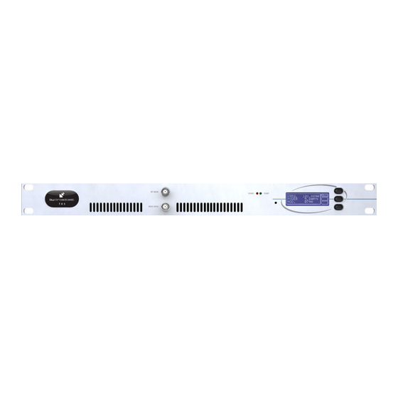
Introduction FRONT AND REAR PANELS Page 12 BW Broadcast technical manual... -
Page 13: Control And Monitor Lcd
The power amplifier voltage will vary depending on set output power and the presence of any fault conditions which also cut the voltage back and with it the R.F. output. Page 13 BW Broadcast technical manual... -
Page 14: Installation And Setup
The LCD readout will only display frequencies in 100Khz steps. Any frequency offsets derived from the internal 12.5kHz offset switch will not show on the LCD. Consult a frequency counter if using offsets. Page 14 BW Broadcast technical manual... -
Page 15: Power Setup
The windows application has a button that can toggle the RF output of the trans- mitter. Please consult the RS232 section of this manual for more information on controlling the transmitter remotely. TR ANSMITT ER Page 15 BW Broadcast technical manual... -
Page 16: Alarms
More info is found in the following pages of the manual. BW Broadcast can also customise the alarm / fault software to meet the requirements of major broadcast- ers and networks or supply N+1 solutions. More information on this and other custom features can be obtained from our technical department. -
Page 17: Terminal Control Of The Transmitter
The transmitter is internally set to communicate at 9600 bps, no parity with 1 stop bit and hardware flow control. This is commonly known as 9600 8N1. If your using Windows then you can use the pre-bundled terminal program “Hyper-terminal”. This is located in the Programs -> Accessories -> Communications folder accessible Page 17 BW Broadcast technical manual... - Page 18 'Enter’ key a few Reset alarms (all to 0 / off) times in succession. Mute R.F. Unmute R.F. ENTER Refresh screen Page 18 BW Broadcast technical manual...
-
Page 19: Modes Of Operation
Page 19 BW Broadcast technical manual... - Page 20 L and R inputs, will produce proper summed mono operation and no spurious 38kHz signals. Page 20 BW Broadcast technical manual...
-
Page 21: Multiplex / Broadband Input
BNC socket. See loopthrough mode below * JUMPERS. J5 (ON), J6 (STEREO), DSW1 (ON / OFF), DSW2 (50 / 75), DSW3 (STEREO), DSW4-8 (OFF) Page 21 BW Broadcast technical manual... -
Page 22: Mono From Two Channels
This is to stop the internal stereo encoder’s multiplex output signal from being fed to the exciter section internally. More information on loopthrough setup is provided at the end of the advanced setup procedure section. Page 22 BW Broadcast technical manual... - Page 23 5. Connect an audio source to both channels and apply a 400Hz tone with a level of +6dBu. Page 23 BW Broadcast technical manual...
- Page 24 Otherwise, switch it back to on and set DIP switch 2 to the correct setting for your region, 75µs for the Americas and Japan and 50µs for the rest of the world. Page 24 BW Broadcast technical manual...
-
Page 25: Other Setup Considerations
VC1. LCD SYSTEM METERING ACCURACY DISPLAY Measurement Accuracy POWER SUPPLY Volts +/-1 Volt TEMPERATURE Degrees Centigrade +/-1 Degree PEAK DEVIATION +/-1 kHz RF POWER Watts Page 25 BW Broadcast technical manual... -
Page 26: Technical Data
489mm x 44mm x 322mm Size 3 kg Weight 85 - 260 VAC Voltage input 110V - 4A / 220V - 2A Current input IEC, FUSED and switchable Power connector UL / TUV / CE Switched mode approvals Page 26 BW Broadcast technical manual... -
Page 27: Circuit Description
The audio from the DAC is buffered through IC2 and IC7. These buffer op-amps drive into the analogue switches (IC6). The switches are controlled by the microcontroller IC5 and the output from the switches feed into three Page 27 BW Broadcast technical manual... - Page 28 D-type from the microcontroller on the LCD board together with connections for the modulation level and a serial interface which provides frequency and status information between the PLL microcontroller on the combo board and the main system microcontroller on the LCD board. Page 28 BW Broadcast technical manual...
-
Page 29: Lcd Control Board
R21 and CON1. R22 and C15 provide supply decoupling for the op-amp. C14,15,16,17,18 provide further decoupling and feedback for the power control feedback loop formed around side B of the op-amp. Page 29 BW Broadcast technical manual... -
Page 30: Power Amplifier Board
PA voltage, 18 volts from the regulator off the AUX power line to power the LCD control board and the combo board, and last but not least the PA power modules control line which controls it’s output voltage. Page 30 BW Broadcast technical manual... -
Page 31: Block Diagram
Technical data BLOCK DIAGRAM Page 31 BW Broadcast technical manual... - Page 32 Technical data WIRING AND INTERNAL OVERVIEW Page 32 BW Broadcast technical manual...
-
Page 33: Schematics
Technical data 3.51 COMBO BOARD SCHEMATICS 3.511 DSP Limiter section Page 33 BW Broadcast technical manual... -
Page 34: Coder Section
Technical data 3.512 Stereo encoder section Page 34 BW Broadcast technical manual... -
Page 35: Exciter Section
Technical data 3.513 PLL exciter section Page 35 BW Broadcast technical manual... - Page 36 Technical data 3.514 Digital Input section Page 36 BW Broadcast technical manual...
- Page 37 Technical data 3.52 LCD CONTROL BOARD Page 37 BW Broadcast technical manual...
- Page 38 Technical data 3.53 Power amplifier board Page 38 BW Broadcast technical manual...
-
Page 39: Parts List
6K8 0.1W 0805 Thick Film Resistor 1% 5K6 0.1W 0805 Thick Film Resistor 1% 4K3 0.1W 0805 Thick Film Resistor 1% R91,R96 3K3 0.1W 0805 Thick Film Resistor 1% 120K 0.1W 0805 Thick Film Resistor 1% Page 39 BW Broadcast technical manual... - Page 40 4p7 0805 Multi-layer Ceramic 50V C0G / NP0 Capacitor 18pF 0805 Multi-layer Ceramic 50V C0G / NP0 Capacitor 4.7uF 0805 Multi-layer Ceramic 25V X5R / X7R Capacitor 39pF 0805 Multi-layer Ceramic 50V Capacitor 1% C105 470nF 0805 Multi-layer Ceramic 50V X7R Capacitor Page 40 BW Broadcast technical manual...
- Page 41 2 Way Screwless 45 degree PCB Mount Terminal Block Filtered Dual 9 Way Right Angle PCB Mount D-Type CON6 Connector BNC Right Angle PCB-Mount Non-insulated Connector CON7,CON8 50Ohm 3Pin XLR Female R/A PCB Mount Non-Insulated Chas- CON9,CON10 sis Socket Page 41 BW Broadcast technical manual...
- Page 42 Connector 20-Way Header Strip (20-Way) LCD Screen Blue LCD Display 40-Pin 40 Pin IC Socket IC2,IC3 8-Pin 8-Pin IC Socket Panel Buttons Molded Cap for Switch (NOT FITTED) Con1 10-Way 10 Way Boxed Header Page 42 BW Broadcast technical manual...
- Page 43 1/4W Metal Film Resistor- Runs on underside of board CA3240EZ Op-Amp IC1, IC2 VN66AFD LM335Z Temp Sensor LM2575T-ADJ Adjustable switcher voltage reg REG1 L7818CV L7818CV Voltage Regulator REG2 Aavid Heatsink Heatsink for TO220 Package Thermalloy Page 43 BW Broadcast technical manual...
- Page 44 Con3, Con4, Con5 Ferrite Core Yellow/Red Ferrite Core S37-8/90 RFT1 Scientific Wire Self Fluxing Enamelled Copper Wire RFT1 Semi Rigid 50Ohm Semi-Rigid Coax EZ50-.090 - 28mm RFT1 Coax Ceramic Ceramic insulator Insulator R23 to ground Page 44 BW Broadcast technical manual...
- Page 45 www.bwbroadcast.com...
Need help?
Do you have a question about the TX5 FM Broadcast Transmitter and is the answer not in the manual?
Questions and answers