Table of Contents
Advertisement
Quick Links
TX1000 / TX1500
FM Broadcast Transmitter
Technical Manual
v2.1
No part of this manual may be re-produced in any form without prior written permission from BW Broadcast.
The information and specifications contained in this document is subject to change at any time without notice.
Copyright 2012 BW Broadcast
www.bwbroadcast.com
Advertisement
Table of Contents

Related Manuals for BW Broadcast TX1000


Summary of Contents for BW Broadcast TX1000
- Page 1 Technical Manual v2.1 No part of this manual may be re-produced in any form without prior written permission from BW Broadcast. The information and specifications contained in this document is subject to change at any time without notice. Copyright 2012 BW Broadcast...
- Page 2 WARNING This transmitter should never be operated without a suitable antenna or test dummy load! Failure to observe this requirement may result in damage to the transmitter that is not covered by the warranty. IMPORTANT This transmitter has been shipped with the internal stereo generator enabled. The internal jumper J5 (MPX loop-through) is set to ON.
-
Page 3: Table Of Contents
3.513 Exciter section 3.514 Digital Input Section 3.52 LCD control section 3.53 Power amplifier section Parts List 3.61 Combo board parts list 3.62 LCD control board parts list 3.63 Power amplifier board parts list Page 3 BW Broadcast technical manual... - Page 4 Introduction TX1000+/1500+ FM TRANSMITTER The BW Broadcast TX1000+/1500+ is a high specification FM broadcast transmitter. Its broadband “no-tune” design allows 87.5-108 MHz operation from internal direct reading rotary switches or the front panel LCD frequen- cy control system if enabled. Digital PWM techniques provide an easily adjustable and accurate automatic level controlled R.F.
-
Page 5: Introduction
If the product shows any defects within the specified warranty period that are not due to normal wear and tear and/or improper handling by the user, BW Broadcast shall, at its sole discretion, either repair or replace the product. If the unit has a manufacturers fault within twenty eight (28) days then BW Broadcast will pay the freight at their discretion. -
Page 6: Safety
SCH and has been issued with WEE/FA0268RX as its unique producer ID by the appro- priate environment agency. BW Broadcast Ltd full comply with it explicit responsibilities, subject to WEEE Collections Policy outlined in their General Terms and conditions of Sale, when it sells Electrical and Electronic Equipment (EEE) to B2B customers in the UK and EU. - Page 7 Adjust the desired power output level using front panel. Check reflected power is OK. That finishes the set-up. A much more detailed explanation is available in the appropriate sections of this manual as well as additional options. You should read through it! Page 7 BW Broadcast technical manual...
- Page 8 That finishes the set-up. A much more detailed explanation is available in the appropriate sections of this manual as well as additional options. You should read through it! IN OUT RF OUT BW Broadcast Transmitter Page 8 BW Broadcast technical manual...
- Page 9 That finishes the set-up. A much more detailed explanation is available in the appropriate sections of this manual as well as additional options. You should read through it! IN OUT IN OUT RF OUT RF OUT BW Broadcast BW Broadcast Transmitter Transmitter Page 9 BW Broadcast technical manual...
- Page 10 Check the documentation that came with your RDS encoder on how to set/check the proper RDS injec- tion level. That finishes the set-up. A much more detailed explanation is available in the appropriate sections of this manual as well as additional options. You should read through it! Page 10 BW Broadcast technical manual...
- Page 11 Check the documentation that came with your RDS encoder on how to set/check the proper RDS injec- tion level. That finishes the set-up. A much more detailed explanation is available in the appropriate sections of this manual as well as additional options. You should read through it! Page 11 BW Broadcast technical manual...
-
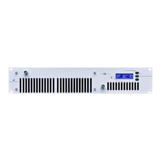
Page 12: Front And Rear Panels
Introduction FRONT AND REAR PANELS Page 12 BW Broadcast technical manual... -
Page 13: Installation And Setup
The LCD readout will only display frequencies in 100Khz steps. Any frequency offsets derived from the internal 12.5kHz offset switch will not show on the LCD. Consult a frequency counter if using offsets. Page 14 BW Broadcast technical manual... -
Page 14: Power Setup
The windows application has a button that can toggle the RF output of the trans- mitter. Please consult the RS232 section of this manual for more information on controlling the transmitter remotely. FM TRANSMITTER Page 15 BW Broadcast technical manual... -
Page 15: Alarms
More info is found in the following pages of the manual. BW Broadcast can also customise the alarm / fault software to meet the requirements of major broadcasters and networks or supply N+1 solutions. More information on this and other custom features can be obtained from our technical department. - Page 16 The power amplifier voltage will vary depending on set output power and the presence of any fault conditions which also cut the voltage back and with it the R.F. output. Page 13 BW Broadcast technical manual...
-
Page 17: Terminal Control Of The Transmitter
R.F., change the frequency, change the R.F. power and reset any alarm flags that have been set. Remote Control Application 2.43 Terminal control of the transmitter Installation Please see the instructions for your terminal software package to find out how to connect to a remote serial Page 17 BW Broadcast technical manual... - Page 18 ENTER Refresh screen screen or by asking for several refresh screens by pressing the 'Enter’ key a few times in succession. Page 18 BW Broadcast technical manual...
-
Page 19: Modes Of Operation
Page 19 BW Broadcast technical manual... - Page 20 L and R inputs, will produce proper summed mono operation and no spurious 38kHz signals. Page 20 BW Broadcast technical manual...
-
Page 21: Multiplex / Broadband Input
BNC socket. See loopthrough mode below * JUMPERS. J5 (ON), J6 (STEREO), DSW1 (ON / OFF), DSW2 (50 / 75), DSW3 (STEREO), DSW4-8 (OFF) Page 21 BW Broadcast technical manual... - Page 22 This is to stop the internal stereo encoder’s multiplex output signal from being fed to the exciter section internally. More information on loopthrough setup is provided at the end of the advanced setup procedure section. Page 22 BW Broadcast technical manual...
-
Page 23: Stereo
5. Connect an audio source to both channels and apply a 400Hz tone with a level of +6dBu. Page 23 BW Broadcast technical manual... -
Page 24: Mono
Otherwise, switch it back to on and set DIP switch 2 to the correct setting for your region, 75µs for the Americas and Japan and 50µs for the rest of the world. Page 24 BW Broadcast technical manual... -
Page 25: Other Setup Considerations
VC1. LCD SYSTEM METERING ACCURACY DISPLAY Measurement Accuracy POWER SUPPLY Volts +/-1 Volt TEMPERATURE Degrees Centigrade +/-1 Degree PEAK DEVIATION +/-1 kHz RF POWER Watts Page 25 BW Broadcast technical manual... -
Page 26: Specifications
I/O Alarms D9-type Male; RS232 D9-Type Female Size 482mm x89mm x 422mm Weight 15 kg Voltage input 220 - 260 VAC Current input Power connector 16A C19 IEC, FUSED and switchable Switched mode approvals UL / TUV / CE Page 26 BW Broadcast technical manual... -
Page 27: Circuit Description
(IC6). The switches are controlled by the microcontroller IC5 and the output from the switches feed into three resistors R82,83,84 to provide a D/A type function producing the multiplex signal. The resistors are carefully chosen to provide sine weighting for the reconstruction, which keeps the lower order harmonic content down to Page 27 BW Broadcast technical manual... - Page 28 D-type from the microcontroller on the LCD board together with connections for the modulation level and a serial interface which provides frequency and status information between the PLL microcontroller on the combo board and the main system microcontroller on the LCD board. Page 28 BW Broadcast technical manual...
-
Page 29: Lcd Control Board
R21 and CON1. R22 and C15 provide supply decoupling for the op-amp. C14,15,16,17,18 provide further decoupling and feedback for the power control feedback loop formed around side B of the op-amp. Page 29 BW Broadcast technical manual... -
Page 30: Power Amplifier Board
VSWR and PA control signals together. Output of IC1B is then a final control signal that controls the output of the power amplifier by controlling it's power supply voltage. R27 and VR3 set the voltage reference to the inverting Page 30 BW Broadcast technical manual... - Page 31 The output of the low pass filter is sniffed by VSWR sensors R4, R5, C3, D2, C4 and R6, R7, C5, D3, C6 which generate forward and reverse RF power measurements for metering and for VSWR fault protection and alarms. Page 31 BW Broadcast technical manual...
-
Page 32: Block Diagram
Technical data BLOCK DIAGRAM Page 32 BW Broadcast technical manual... - Page 33 48V 1600W POWER SUPPLY DOUBLE PALLET AMP DOUBLE PALLET AMP PSU Interface board Filtered Power PCB 10 WAY RIBBON PA Controller PCB INPUT SPLITTER 15W DRIVER BOARD LCD Board RF Mon BNC Mod Mon BNC Page 33 BW Broadcast technical manual...
-
Page 34: Schematics
Technical data 3.51 COMBO BOARD SCHEMATICS 3.511 DSP Limiter section Page 34 BW Broadcast technical manual... -
Page 35: Stereo Encoder Section
Technical data 3.512 Stereo encoder section Page 35 BW Broadcast technical manual... -
Page 36: Exciter Section
Technical data 3.513 PLL exciter section Page 36 BW Broadcast technical manual... -
Page 37: Digital Input Section
Technical data 3.514 Digital Input section Page 37 BW Broadcast technical manual... - Page 38 Technical data 3.52 LCD CONTROL BOARD Page 38 BW Broadcast technical manual...
- Page 39 Technical data 3.531 PSU Interface Page 39 BW Broadcast technical manual...
- Page 40 Technical data 3.532 Bus Bar Page 40 BW Broadcast technical manual...
- Page 41 Technical data 3.533 Fan Connector Board Page 41 BW Broadcast technical manual...
- Page 42 Technical data 3.534 D to IDC Board Page 42 BW Broadcast technical manual...
- Page 43 Technical data 3.535 PA Controller Board Page 43 BW Broadcast technical manual...
- Page 44 Technical data 3.536 PA 15W Driver Board Page 44 BW Broadcast technical manual...
- Page 45 Technical data 3.575 Double Pallet Page 45 BW Broadcast technical manual...
- Page 46 Technical data 3.538 Output Combiner Page 46 BW Broadcast technical manual...
-
Page 47: Parts List
6K8 0.1W 0805 Thick Film Resistor 1% 5K6 0.1W 0805 Thick Film Resistor 1% 4K3 0.1W 0805 Thick Film Resistor 1% R91,R96 3K3 0.1W 0805 Thick Film Resistor 1% 120K 0.1W 0805 Thick Film Resistor 1% Page 47 BW Broadcast technical manual... - Page 48 18pF 0805 Multi-layer Ceramic 50V C0G / NP0 Capacitor 4.7uF 0805 Multi-layer Ceramic 25V X5R / X7R Capacitor 39pF 0805 Multi-layer Ceramic 50V Capacitor 1% C105 470nF 0805 Multi-layer Ceramic 50V X7R Capacitor C106 8200pF 0805 Multi-layer Ceramic 50V Capacitor 5% Page 48 BW Broadcast technical manual...
- Page 49 REG1 L7805CV +5V 1A, Linear Fixed Voltage Regulators REG2 L7815CV +15V 1A, Linear Fixed Voltage Regulator TO220 RFT1 28SWG (0.355mm) Blue/Green Bonded Bifilar Enamelled Wire SW1-SW4 10 Step Decimal Rotary PCB Switch Hole Through Page 49 BW Broadcast technical manual...
- Page 50 330nH 10% SMD 1008 Ferrite Inductor Bead Inductor 10% 0805 600R 100MHZ 47nH MidiSpring Inductor 68nH MidiSpring Inductor 4.7mH 10RB Toko Radial Inductor #181LY-472J 3.9mH 10RB Toko Radial Inductor #181LY-392J L13,L14 220uH Axial Inductor Ferrite 5% Tolerance Page 50 BW Broadcast technical manual...
- Page 51 LCD Screen Blue LCD Display 40-Pin 40 Pin IC Socket IC2,IC3 8-Pin 8-Pin IC Socket Panel Buttons Molded Cap for Switch (NOT FITTED) Con1 10-Way 10 Way Boxed Header Con2 16-Way 16 Way Boxed Header Page 51 BW Broadcast technical manual...
- Page 52 Black Oxide PCB Board (Black) 3.633 Fan connector board Reference Value Description C1,C2 100nF Ceramic disc capacitor 2.5mm Pitch 9Way IDC 9 Way Straight PCB D Plug 45DEG 4 Way, Screwless 45 degree, Terminal Block Page 51 BW Broadcast technical manual...
- Page 53 0805 SMT Capacitor NOTUSED 0805 SMT Capacitor NOTUSED 0805 SMT Capacitor 47uF SMT Electrolytic Capacitor 0805 SMT Capacitor D5-D7 NOTUSED SMT Diode IC1-IC3 CA3240EZ DUAL BIMOS Op-Amp CON1,CON2 NOTUSED CON3 CONN-H10 10 WAY Straight boxed header Page 52 BW Broadcast technical manual...
- Page 54 Choke Inductor Not fitted S18 Toko Inductor UF5401 300A, 100V Fast diode GREEN 5mm Greem LED IRL510 IRL510PBF CON1 MCX PCB Socket N.F CON2 CONN-H2 MCX PCB Socket REG1 LM2575HV-ADJ Step down switch regulator Page 53 BW Broadcast technical manual...
- Page 55 10R 0805 Resistor 110R 100R 0805 Resistor 51R 2512 Resistor NOT FITTED 0805 Resistor C1,C4 0805 Capacitor C2,C3 33pf 0805 Capacitor 47pf 0805 Capacitor D1-D4,D6,D8,D9,D11 BAT54 BAT54 Single Schotky Diode SOT-23 D5,D7,D10,D12 Green LED PCB Board Page 54 BW Broadcast technical manual...
- Page 56 www.bwbroadcast.com...
Need help?
Do you have a question about the TX1000 and is the answer not in the manual?
Questions and answers