Table of Contents
Advertisement
V2 FM TRANSMITTERS
TECHNICAL MANUAL
Document rev 3.2
The software in the transmitter is upgradeable. This manual may refer to an older software version. Note that
previous versions of software may not have all of the features described in the manual. To check the latest
software go to www.bwbroadcast.com/downloads
No part of this manual may be re-produced in any form without prior written permission from BW Broadcast. The
information and specifications contained in this document is subject to change at any time without notice.
©2014 BW Broadcast
www.bwbroadcast.com
Advertisement
Table of Contents
Troubleshooting

Related Manuals for BW Broadcast TX-V2


Summary of Contents for BW Broadcast TX-V2
- Page 1 To check the latest software go to www.bwbroadcast.com/downloads No part of this manual may be re-produced in any form without prior written permission from BW Broadcast. The information and specifications contained in this document is subject to change at any time without notice.
-
Page 2: Table Of Contents
The TX-V2 ........ - Page 3 II Initial Setup and connections Installation ........Quick Start .
- Page 4 7.5.9 RS232 ........7.5.10 Log .
- Page 5 8.1.4 FSK (for translators in the USA) ......8.1.5 RF Mute on Silence ......8.1.6 RF Mute (Manual) .
- Page 6 8.5.12 HTTP ........8.5.13 Telnet .
- Page 7 10.2.5 TX600 V2 ........10.2.6 TX1000 V2 .
-
Page 8: I Introduction
Part I Introduction... -
Page 9: The Tx-V2
Also present are 4 rear panel opto-isolated triggers that al- low external equipment to control the transmitter. It is advised that this manual is read to learn all of the advanced features of the TX-V2 Trans- mitter. -
Page 10: Warranty
30 days of receipt of the product at BW Broadcast. If the product needs to be modified or adapted in order to comply with applicable technical or safety standards on a national or local level, in any... - Page 11 No other person (retail dealer, etc.) shall be entitled to give any warranty promise on behalf of BW Broadcast. Claims for damages: Failure of BW Broadcast to provide proper warranty service shall not entitle the buyer to claim (consequential) damages. In no event shall the liability of BW Broadcast exceed the invoiced value of the product.
-
Page 12: Safety
Safety MAINS VOLTAGE: TX5 V2 - TX600 V2 operate from an AC power source between 110 and 240 V. TX1000 V2 - TX2500 V2 operate from a power source be- tween 220 and 240 V. WARNING: To avoid damage DO NOT CONNECT TO 110V. - Page 13 Compliance PCS number WEE/P3438PR/ SCH and has been issued with WEE/FA0268RX as its unique producer ID by the appropriate en- vironment agency. BW Broadcast Ltd full comply with it explicit re- sponsibilities, subject to WEEE Collections Policy outlined in their Gen- eral Terms and conditions of Sale, when it sells Electrical and Elec- tronic Equipment (EEE) to B2B customers in the UK and EU.
- Page 14 Heed Warnings: All warnings on the appliance and in the operating instructions should be adhered to. Follow instructions: All operation and user instructions should be followed. Water and Moisture: The appliance should not be used near water (e.g. near a bathtub, washbowl, kitchen sink, laundry tub, in a wet basement, or near a swimming pool etc.).
- Page 15 Damage Requiring Service: The appliance should be serviced by qualified service person- nel when: • The power supply cord or the plug has been damaged; or • Objects have fallen, or liquid has been spilled into the appliance; or • The appliance has been exposed to rain; or •...
-
Page 16: Front And Rear Panels
Front and Rear Panels 4.1 1U (TX5, TX30, TX50) -
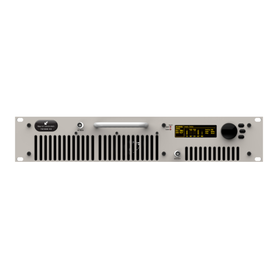
Page 17: Tx300, Tx600)
4.2 2U (TX300, TX600) -
Page 18: Tx1000, Tx1500)
4.3 2U (TX1000, TX1500) -
Page 19: Tx2500)
4.4 3U (TX2500) -
Page 20: User Interface
User Interface 5.1 Input Interface The TX-V2 has an intuitive interface based around a pushable scroll wheel and three buttons. Push to Enter Exit Help Meters 5.1.1 Navigating the menu The menu is navigated by rotating the scroll wheel, pushing it in to open a submenu. Within in a submenu, pressing exit will return to the parent menu. -
Page 21: Display
5.2 Display 5.2.1 Status Box This section of the display gives real time information about the status of the transmitter A Frequency The target frequency of the transmitter. When the transmitter is tuning to frequency on start-up (out of lock), this will flash between full and half brightness, When the transmitter is locked (has reached frequency), it will remain at full brightness. -
Page 22: Menu Box
- All alarms are triggered. An indication the alarms have been triggered will also be shown on the screensaver. E PA temperature/Power supply voltages/Reverse power Displays the temperature of the Power Amplifier, the voltages of the Power amplifier power supply and of the auxiliary power supply and the reverse power: •... -
Page 23: Meters
5.2.3 Meters V2 Transmitters offer extensive metering with just a few clicks of the bottom menu button. Click the menu button to cycle through each of the 3 meters screens: RF Status, Audio Status and Config. Status. To leave the meters screen press the exit button. -
Page 24: Initial Setup And Connections
Part II Initial Setup and connections... -
Page 25: Installation
Installation 6.1 Quick Start N.B. Never power on an FM transmitter without a suitable antenna or dummy load connected. The V2 Transmitter’s protection circuitry will prevent any internal damage, but it is not advis- able to run an FM transmitter without a load connected. Setting up a V2 Transmitter couldn’t be any easier. -
Page 26: Examples Of Use
Encoder Selects the stereo generator mode, from either: Stereo, Mono L+R, Mono L, Mono R and Swap L + R. MPX Source Selects if the MPX source for the exciter is internal or external. If using the V2 trans- mitter with no external equipment (RDS, audio processor etc) then set to internal. If using any external equipment set to external. -
Page 27: Transmitter With An External Audio Processor
4. Connect the Baseband/MPX output on the back of the transmitter to the MPX input of the RDS encoder. 5. Connect the MPX output of the RDS encoder to the MPX input on the back of the trans- mitter. 6. Plug the power cord into the power supply module on the rear panel of the transmitter. 7. -
Page 28: Transmitter With An External Audio Processor And Rds (In Line Connection)
3. Connect the MPX output of your audio processor (or stereo generator) to the MPX input on the back of the transmitter. 4. Plug the power cord into the power supply module on the rear panel of the transmitter. 5. Connect the required remote control / monitoring ports (Ethernet, RS232, Alarms/Triggers Port). -
Page 29: Transmitter With An External Audio Processor And Rds (Side Chain Connection)
3. Connect the MPX output of your audio processor (or stereo generator) to the MPX input of your RDS encoder. 4. Connect the MPX output of your RDS encoder to the MPX input on the back of the trans- mitter. 5. - Page 30 1. Place the transmitter in a well ventilated space 2. Connect the antenna to the RF output connector on the back of the transmitter. 3. Connect the MPX output of your audio processor (or stereo generator) to the MPX input on the back of the transmitter.
-
Page 31: System Configuration
Part III System Configuration... -
Page 32: Operation Guide
Operation Guide 7.1 RF Settings N.B. Never power on an FM transmitter without a suitable antenna or dummy load con- nected. The V2 Transmitter’s protection circuitry will prevent any internal damage, but it is not advisable to run an FM transmitter without a load connected. 7.1.1 Basic Setup 1. -
Page 33: Audio Settings
5. Set Enable to Enabled. The power Scheduler is now running. 7.2 Audio Settings BW Broadcast’s range of award winning DSPX audio processors has become known for their features, performance and value for money. Integrated within all V2 Transmitters is the 4- band DSPXmini FM SE. -
Page 34: Alarms
Triggers are used to control certain parameters on the V2 Transmitter using the relevant pins on the rear alarms and triggers connector. To fire a trigger, the pin must be pulled low. To set up a trigger: 1. Connect the required trigger pin to the required source. Make sure that the voltage and current levels are compatible. -
Page 35: System
2. Navigate to the Alarms folder and then enter the Alarm folder that you require (Alarm A, B, C). 3. Set Type to Alarm. 4. Set the source for the Alarm. For a detailed description consult the parametric guide section on Alarms. 5. -
Page 36: Screen Saver
7.5.3 Screen Saver 1. Select the Screen Saver time-out before the Screensaver starts. 2. Enable or disable Screen Lock as required. If enabled, enter the desired 4 digit Screen Lock Code. This code will be requested in order to exit the screen saver screen. 7.5.4 Users 1. -
Page 37: E-Mail
BW Broadcast. Please note that SSL authentication is not supported by the unit. The easier option to set up is to send the email via the BW Broadcast email relay service. In this case, the unit must be connected to the internet in order to connect to the service. -
Page 38: Http
7.5.7 HTTP V2 Transmitters provide a graphical web based interface for ease of use and control. This can be accessed by navigating to the IP address of the unit in any standard web browser. After entering the login details for the unit, the user can then read and write all parameters and also perform firmware upgrades. -
Page 39: Rs232
7.5.9 RS232 V2 Transmitters offer many options for remote monitoring and control. All parameters avail- able on the front panel are available remotely. To connect to the unit via RS232 connection, connect a standard serial cable between the transmitter and the PC, and use the following settings for the COM port: •... - Page 40 Logging to a File in internal memory If enabled, the system will keep logs of the last 31 days. These logs can be accessed through the web remote. An example section from a log file is shown below: 2013-04-22 11:40:06 DTLG > M: exciter_locked = 1 DTLG >...
-
Page 41: Diagnostics
7.5.11 Diagnostics This set of parameters report the state of various parts of the system upon boot (OK or fail). If an error condition is observed, the unit should be re-booted and these parameters should be examined. This information will be useful when contacting support. 7.5.12 About The about menu contains the version numbers of the different parts of the system. -
Page 42: Web Remote Interface
7.6.2 Web Remote Interface The user interface is divided in several sections: Status Bar, Alarms and Notifications, Naviga- tion Bar and Transmitter Controls. Status Bar The Status Bar displays the current status of the Transmitter (Frequency, FWD power in Watts, REV power in Watts, peak Deviation in kHz). - Page 43 TX-V2.log.1 corresponds to yesterday’s log, TX-V2.log.2 corresponds to the log written two days ago and so on. Note that if the unit is switched off, It will not write to the log and it will not create a new log file for the number of days it is off, so the older log files in this case will correspond to previous logs (written several days ago).
-
Page 44: Text Based Access (Telnet Or Serial Rs232)
G Disconnect Clicking this button closes the active web remote session. H Transmitter Controls All the controls in the transmitter can be found in this section. These are the same op- tions that can be found in the Front Panel Controll System on the transmitter itself. Click on the Help Icon (?) located on the top left of the screen or refer to the relevant sections of this manual to understand any particular feature. -
Page 45: Web Api
get parameter_id This command returns the current value of the parameter requested. e.g. TX V2> get transmitter.frequency 98.00MHz set parameter_id parameter_value This command sets the parameter requested to the value specified. e.g. TX V2> set transmitter.power 150 reboot This command reboots the unit. Please note - there will be no confirmation stage, if you send this command the unit will re- boot immediately, taking your transmitter temporarily off-air. -
Page 46: Authentication
7.8.1 Authentication Logging in In order be able to read or modify parameters through the Web API, the user must first au- thenticate by sending the following request: ”http://IP_ADRESS/api/auth?password=PASSWORD Where IP_ADRESS is the IP Adress of the unit and PASSWORD is the password set in the Font Panel (System ⇒... -
Page 47: Reading Parameters
7.8.3 Reading Parameters Reading one Parameter To get the value of a specific parameter, use the following request: ”http://IP_ADRESS/api/getParameter?id=PARAMETER_NAME” e.g: ”http://192.168.5.34/api/getParameter?id=transmitter.power” Response with xml content (text/xml): ”<parameters> <parameter id=”transmitter.power” value=”5.40”/> </parameters>” Reading all the Parameters To get a list with all the parameters, use the following request: ”http://IP_ADRESS/api/getparameters”... -
Page 48: Reading Meters
The following request will return a page with all the values for the different meters: ”http://IP_ADRESS/api/streammeters” 7.8.5 Reading log files The following request will return a page with the latest log contained in the unit (today’s log): ”http://IP_ADRESS/TX-V2.log” To access old log files, use the following requests: For yesterday’s log: ”http://IP_ADRESS/TX-V2.log.1”... -
Page 49: Parameters
7.9 Parameters This section contains a list of all the parameters in the unit and all of their possible values. This should must be used as a reference when controlling the unit via text based access (Telnet or Serial RS232) or the Web API. When setting the value of a parameter, trying to set a value greater than the allowed maxi- mum will result in the maximum value being set. - Page 50 Transmitter Model Minimum Power Maximum Power Step Size 0.05 5.05 0.05 TX30 30.15 0.45 TX50 50.4 0.45 TX300 30.8 310.8 TX600 60.5 610.5 TX1000 1102 TX1500 1512 13.5 TX2500 520.5 2550 20.5 e.g.: ”set transmitter.set_power 50” MPX Source mpx.source Options: int (for internal), ext (for external) transmitter.fsk_interval Options: off, 3600 (sends every hour) FSK ID...
-
Page 51: Audio Settings
Start Time powerscheduler.starttime Range: time in format hh:mm:ss or hh.mm.ss e.g.: ”set powerscheduler.starttime 12:30:30” Finish Time powerscheduler.finishtime Range: time in format hh:mm:ss or hh.mm.ss Current Time system.time Range: time in format hh:mm:ss or hh.mm.ss This parameter can be get or set. 7.9.2 Audio Settings MPX Source mpx.source... -
Page 52: Triggers
Value Preset Bypass Tight Loud Smooth Clean Bright RockNRoll Low Bass Urban Talk Classic Bright Classic Bright 2 Pre-Emphasis audio.preemphasis Options: Options: 0 (for Off), 50 (50 us), 75 (75us) Audio Mode audio.stereo Options: stereo, mono_lr (for Mono L+R), mono_l (Mono L), mono_r (Mono R), swap_lr (Swap L/R) 7.9.3 Triggers The following parameters can be used to configure any trigger (trigger[x], where x is 1 to 4) -
Page 53: Alarms
(ON) Message trigger[x].message.on Accepts up to 300 characters of text. 7.9.4 Alarms Type alarm[x].type Options: alarm, telemetry (for Analog Out) Source (for Analog Out) alarm[x].telemetrysource Options: fwdpow (for Fwd Power), revpow (Rev Power), pavolts (PA Volts), auxvolts (Aux Volts), peakmod (Peak Modulation), patemp (PA Temp), rfmute (RF Mute), Modulation Threshold alarm[x].modulation_threshold Range: 1000 to 100000. -
Page 54: System
7.9.5 System Date system.date Range: Date in the following format yyyy-mm-dd e.g.: ”set system.date 2014-02-22” Time system.time Range: Time in the following format hh.mm.ss e.g.: ”set system.time 22:10:55” Uptime system.uptime Read only (get system.uptime) (reads: x days, hh:mm:ss) Location system.location Range: Up to 64 characters of text. - Page 55 Users Username system.username.admin Range: up to 15 characters of text. Password system.username.password Range: up to 15 characters of text. Ethernet DHCP system.ethernet.dhcp Options: off, on DHCP IP system.ethernet.dhcp.ip Range: Read only. Reads IPv4 address in the form aaa.bbb.ccc.ddd DHCP SM system.ethernet.dhcp.sm Range: Read only.
- Page 56 Range: Read only. Reads IPv4 address in the form aaa.bbb.ccc.ddd Static SM system.ethernet.static.sm Range: Read only. Reads IPv4 address in the form aaa.bbb.ccc.ddd Static GW system.ethernet.static.gw Range: Read only. Reads IPv4 address in the form aaa.bbb.ccc.ddd Static DNS 1 system.ethernet.static.dns[1] Range: Read only.
- Page 57 Recipient(s) email.recipient Range: Accepts up to 99 characters of text. Port smtp.port Range: 1 to 1024 Username smtp.username Range: Accepts up to 64 characters of text Password smtp.password Range: Accepts up to 64 characters of text Max emails a day email.limit.daily Range: 1 to 1000 Emails sent today...
- Page 58 Telnet Enable system.telnetd.active Options: off, on Port system.telnetd.port Range: 1 to 1024 RS232 Enable system.rs232d.active Options: off, on Baud rate system.rs232d.baud Options: 9600, 19200, 38400, 57600, 115200 RS232 system.logging.rs232.active Options: off, on File system.logging.file.active Options: off, on...
- Page 59 Log: UDP Enable system.logging.udp.active Options: off, on system.logging.udp.ip Range: IPv4 address in the form aaa.bbb.ccc.ddd Port system.logging.udp.port Range: 1 to 10000 Diagnostics DSPX Comm system.diagnostics.dspx Options: Read only (OK, FAIL) Exciter Comm system.diagnostics.exciter Options: Read only (OK, FAIL) Alarms DAC system.diagnostics.alarmsdac Options: Read only (OK, FAIL) Power DAC...
- Page 60 About Product ID system.product.id Range: Read only. Reads back the product ID (TXxxx) e.g.: ”TX50”. Product Version system.product.version Range: Read only. Reads back the product version (e.g.: ”3.3”). Serial Number system.serial_number Range: Read only. Reads back the Hardware version (e.g.: ”12”). Hardware Version system.hardware.version Range: Read only.
- Page 61 Factory Reset Factory Reset system.factory_reset Options: yes (to perform the factory reset). Note that all the user settings will be lost and unit will load the default values for all the parameters.
-
Page 62: Parameter Guide
Parameter Guide 8.1 RF Settings 8.1.1 Frequency This sets the transmission frequency. The range for this parameter depends on the Band. For normal Band II transmitters the range is 87.5 MHz to 108 MHz. The normal step size is 50 kHz. Other frequency ranges and step sizes are also available on request. -
Page 63: Fsk (For Translators In The Usa)
8.1.4 FSK (for translators in the USA) V2 Transmitters support automatic station identification using frequency shift keying (FSK). FSK sends a user defined ID once every hour using Morse code and shifting the carrier frequency up by 12.5kHz at 20 words per minute. FSK ID If enabled, the FSK ID will be sent once every hour. -
Page 64: Audio Settings
Enable Enables/disables Power Scheduling. Power Selects the power that the transmitter will produce during the scheduled interval. Start Time Selects the time at which the output power will change from normal power to scheduled power. Finish Time Selects the time at which the output power will change from scheduled power to normal power. -
Page 65: Processing Preset
8.2.3 Processing Preset BW Broadcast’s range of award winning DSPX audio processors has become known for their features, performance and value for money. Integrated within all V2 Transmitters is the 4- band DSPXmini FM SE. This parameter selects the audio processing preset that the internal au- dio processor will use. -
Page 66: Action
US Toll Free: 1-888-233-1663 Email: support@bwbroadcast.com Please note that this is an automatic email alert generated by a BW Broadcast TX-V2. To pre- vent further emails please clear the cause of the alarm or turn off alarm emails on the TX-V2’s control system.”... -
Page 67: Alarms
8.4 Alarms Alarms on the V2 Transmitter are used to indicate that a failure condition is met. They can be set to trigger on Modulation level, Forward power, Reverse power and PLL lock fail. Upon triggering they will toggle the relevant pin on the rear alarms and trigger connec- tor. - Page 68 C Threshold Selects the threshold value that will be used to detect the error condition. This doesn’t apply to the PLL Lock Fail alarm. D Pin Polarity Selects whether the alarm output pin is active high or active low. When +ve is selected, the output will act as a 430 Ohm resistor to ground when the alarm is active and as a 100 KOhm resistor to ground when the alarm is not active and vice-versa if -ve is selected.
- Page 69 Example 2: We would like the system to fire alarm B with inverted polarity when the modula- tion level has dropped below 30 kHz for longer than 15 seconds and release alarm B when the modulation level rises above that level for 5 seconds. This is a way of detecting that silence being transmitted.
-
Page 70: System
Alarms pins as Analogue Outputs When the alarm Type is set to be Analog Out, the alarm pin will report the status parameter selected in Source as an analogue voltage on the alarms pins. This setup is typically used to connect the unit to remote control equipment (also known as telemetry interfaces). The Souce can be set to any of the following parameters: Fwd Power, Rev Power, PA Volts, Aux Volts, Peak Modulation, PA Temp, RF Mute. -
Page 71: Time
8.5.2 Time System Time. This is backed up by an internal battery. 8.5.3 Uptime Reports how long the unit has been powered on for. This parameters accepts up to 20 char- acters of text. 8.5.4 Location Stores the Physical location of the device (e.g. ’TX Site 3, Rack 5’) It accepts up to 64 char- acters of text. -
Page 72: Ethernet
Password This is the password for the remote login. It accepts text of up to 15 characters 8.5.10 Ethernet The V2 Transmitters have a built in web server which can monitor and control all transmitter parameters remotely without the need to install any software. The unit can use either static or dynamic IP addressing. -
Page 73: E-Mail
Please note that SSL authentication is not supported by the unit. An easier option to set up is to send the email via the BW Broadcast email relay service. In this case, the unit must be connected to the internet. -
Page 74: Http
Parameters when Send via is set to BW Broadcast: A From Sets the email address of the sender. The unit will send e-mails through this address. This parameters accepts up to 64 characters of text. B Recipient(s) Sets the recipients of the emails. Multiple addresses must be separated by commas. -
Page 75: Rs232
Enable Enables/disables the telnet server. Port Sets the telnet TCP port. Telnet must be set to Disabled to change. This parameter accepts values from 1 to 1024. 8.5.14 RS232 Enable Enables/disables the RS232 remote. Baud Rate Sets the RS232 baud rate. 8.5.15 Log V2 Transmitters have three methods of logging, regardless of the log location, the format is the same. -
Page 76: Diagnostics
A Enable Enables/disables logging messages to a remote UDP logging/syslog server. B IP Sets the IP address where the log messages should be sent via UDP. This parameter accepts IPv4 addresses in the form aaa.bbb.ccc.ddd. C Port Sets the port where the log messages should be sent via UDP. Disable UDP to change. -
Page 77: Reboot
Product Version This read only parameter displays the product version. Serial Number This read only parameter displays the serial number. Hardware Version This read only parameter displays the HW version. Software Version This read only parameter displays the SW version. Control Version This read only parameter displays the control board version. -
Page 78: Troubleshooting
Part IV Troubleshooting... -
Page 79: V2 Fm Transmitter Troubleshooting Guide
• Check that the set power on the menu to the desired RF power. (BW Broadcast trans- mitters are set to minimum output power when they leave the factory. This can be ad- justed on the front panel via RF settings ⇒... - Page 80 Modulation level is too low • Most professional signal sources will be able to drive BW Broadcast transmitters to full de- viation. Some battery-powered or weaker sources, such as PC sound cards, may not be able to provide enough drive to achieve full modulation in the transmitter. If using the...
-
Page 81: Technical Specifications
Part V Technical Specifications... -
Page 82: Technical Specifications
Technical Specifications 10.1 Common Specifications 10.1.1 RF Harmonics better than -75 dBc Spurious <-90dBc Frequency range 87.5 - 108 MHz Frequency steps 50 kHz Frequency selection User interface with display or web remote control Frequency control type Dual speed phase locked loop Frequency stability <+/- 500 Hz (fine adjustment available) Modulation... -
Page 83: Limiter
10.1.4 Limiter Audio input levels -10dB to +24dB for level control, DSP auto levelling Input CMRR > 60dB Audio distortion <0.05% at limiting 1 KHz (bypass preset) Frequency response 20 Hz to 20 kHz +/- 0.2dB (pre-emphasis off) Processing range Processing control range 40dB Pre-emphasis 50 µs,75 µs and 0 µs (off) -
Page 84: Model-Specific Specifications
10.2 Model-Specific Specifications 10.2.1 TX5 V2 Size 485mm x 350mm x 45mm Weight Votlage input 100 - 265 VAC Power connector Switched mode approvals UL / TUV / CE Power Consumption 30W average @ 5W RF Power 0.05W - 5.05W Continuous Power Supply Internal Connector... -
Page 85: Tx50 V2
10.2.3 TX50 V2 Size 485mm x 350mm x 45mm Weight 6.8kg Votlage input 100 - 265 VAC Power connector Switched mode approvals UL / TUV / CE Power Consumption 104W average @ 50W RF Power 5.4W - 50.4W Continuous Power Supply Internal Connector N-type 50 Ohm... -
Page 86: Tx300 V2
10.2.4 TX300 V2 Size 485mm x 510mm x 90mm Weight 6.8kg Votlage input 100 - 265 VAC Power connector IEC C20 (C19 cable) Switched mode approvals UL / TUV / CE Power Consumption 465W average @ 300W RF Power 30.8W - 310.8W Continuous Power Supply Internal Connector... -
Page 87: Tx1000 V2
10.2.6 TX1000 V2 Size 490mm x 510mm x 95mm Weight 13.4kg Votlage input 220 - 240 VAC Power connector IEC C20 (C19 cable) Switched mode approvals UL / TUV / CE Power Consumption 1580W average @ 1000W RF Power 152W - 1102W Continuous Power Supply Slide-in type Connector... -
Page 88: Tx2500 V2
10.2.8 TX2500 V2 Size 490mm x 510mm x 133mm Weight 19.5kg Votlage input 220 - 240 VAC Power connector IEC C20 (C19 cable) Switched mode approvals UL / TUV / CE Power Consumption 3325W average @ 2500W RF Power 520.5W - 2550W Continuous Power Supply 2 x Slide-in Connector... - Page 89 THIS PAGE IS INTENTIONALLY LEFT BLANK...
Need help?
Do you have a question about the TX-V2 and is the answer not in the manual?
Questions and answers