Table of Contents
Advertisement
Quick Links
Advertisement
Table of Contents

Related Manuals for Ricoh G186


Summary of Contents for Ricoh G186
-
Page 1: Service Manual
G186 SERVICE MANUAL 003108MIU... - Page 5 G186 SERVICE MANUAL 003108MIU...
- Page 7 It is the reader's responsibility when discussing the information contained within this document to maintain a level of confidentiality that is in the best interest of Ricoh Corporation and its member companies. NO PART OF THIS DOCUMENT MAY BE REPRODUCED IN ANY FASHION AND DISTRIBUTED WITHOUT THE PRIOR PERMISSION OF RICOH CORPORATION.
- Page 9 Ricoh Corporation. Users of this manual should be either service trained or certified by successfully completing a Ricoh Technical Training Program. Untrained uncertified users utilizing...
- Page 11 Rev. 04/2007 LEGEND PRODUCT COMPANY CODE GESTETNER LANIER RICOH SAVIN SP 5100N G186 SP 5100N Aficio SP 5100N SP 5100N (RLA only) DOCUMENTATION HISTORY REV. NO. DATE COMMENTS 04/2007 Original Printing...
-
Page 13: Table Of Contents
G186 TABLE OF CONTENTS INSTALLATION 1. INSTALLATION ................1-1 1.1 INSTALLATION REQUIREMENTS ............1-1 PREVENTIVE MAINTENANCE 2. PREVENTIVE MAINTENANCE............ 2-1 2.1 PM INTERVALS ..................2-1 REPLACEMENT AND ADJUSTMENT 3. REPLACEMENT AND ADJUSTMENT ........3-1 3.1 GENERAL PRECAUTIONS ON DISASSEMBLY ........3-1 3.1.1 CHECK POINTS FOR SERVICING ..........3-1 3.1.2 RELEASING PLASTIC LATCHES.............3-1... - Page 14 4.3.9 PAPER ROLLED ON THE OPC DRUM ..........4-19 4.4 MALFUNCTION CAUSES AND SOLUTIONS..........4-21 4.4.1 FUSER ERROR ................4-21 4.4.2 LSU (LASER SCANNING UNIT) ERROR ........4-21 4.4.3 MALFUNCTION OF THE GEAR OF THE FUSER DUE TO MELTING4-22 4.4.4 PAPER EMPTY ................4-22 G186...
- Page 15 5.2.7 CLUTCH/ SOLENOID ...............5-8 Usage ....................5-8 Function ....................5-8 5.2.8 FUSER CONTROL................5-8 Usage ....................5-9 5.2.9 LSU ....................5-9 Usage ....................5-9 5.2.10 DEVELOPER CONTROL ............5-10 Usage ....................5-10 Function ....................5-10 5.2.11 CRU COUNTER ................5-11 Usage ....................5-11 Function ....................5-12 5.2.12 PRINT TEST AND OPTION VERSION........5-12 Usage ....................5-12 G186...
- Page 16 Asic (ORION 2) ..................6-7 Memory....................6-8 Others ....................6-9 6.3.2 INTERNAL BLOCK DIAGRAM ............6-9 6.3.3 SENSOR INPUT CIRCUIT ..............6-9 Paper Empty Sensing ................6-9 Paper Sensing on the By-pass Tray ...........6-10 Paper Feeding/ Width Toner Cartridge Sensing .........6-10 Paper Exit Sensing ................6-10 Cover Open Sensing................6-10 G186...
- Page 17 CN15 [COVER OPEN] MAIN ↔ COVER OPEN ........8-8 CN13 [DPX_SOL] MAIN ↔ DUPLEX SOLENOID........8-9 CN9 [LSU] MAIN ↔ LSU ..............8-9 CN4 [CART] MAIN ↔ TONER SENSOR..........8-10 CN17 [SCF] MAIN ↔ SCF B'D ............8-11 CN8 [THERM] MAIN ↔ FUSER ............8-11 G186...
-
Page 19: Read This First
Read This First Precautions In order to prevent accidents and to prevent damage to the equipment, please read the precautions listed below carefully before servicing the printer and follow them closely. Safety Warning Only to be serviced by appropriately qualified service engineers. High voltages and lasers inside this product are dangerous. -
Page 20: Caution For Safety
Caution for safety Toxic material This product contains toxic materials that could cause illness if ingested. If the LCD control panel is damaged, it is possible for the liquid inside to leak. This liquid is toxic. Contact with the skin should be avoided, wash any splashes from eyes or skin immediately and contact your doctor. -
Page 21: Handling Precautions
cause a short circuit leading to an electric shock or fire hazard.. Never touch the plugs on either end of the power cable with wet hands, this can cause electric shock. When servicing the printer remove the power plug from the wall socket. Use caution when inserting or removing the power connector. - Page 22 Do not place any small metal objects, containers of water, chemicals or other liquids close to the printer which if spilled could get into the machine and cause damage or a shock or fire hazard. Do not install the machine in areas with high dust or moisture levels, beside on open window or close to a humidifier or heater.
-
Page 23: Installation
The fuser unit works at a high temperature. Use caution when working on the printer. Wait for the fuser to cool down before disassembly. Do not put fingers or hair into the rotating parts. When operating a printer, do not put hand or hair into the rotating parts (Paper feeding entrance, motor, fan, etc.). - Page 24 assembly, drain off any electrostatic charge on your body by touching a known earth ground. Alternatively, employ a commercially available wrist strap device, which should be removed for personal safety prior to applying power to the unit under test. After removing an electrical assembly equipped with ESDs, place the assembly on a conductive surface, such as aluminum or copper foil, or conductive foam, to prevent electrostatic charge buildup in the vicinity of the assembly.
- Page 25 INSTALLATION PREVENTIVE MAINTENANCE REPLACEMENT AND ADJUSTMENT TROUBLESHOOTING SERVICE TABLES DETAILED DESCRIPTIONS SPECIFICATIONS APPENDIX...
-
Page 27: Installation
INSTALLATION... -
Page 29: Installation Requirements
Installation Requirements 1. INSTALLATION 1.1 INSTALLATION REQUIREMENTS Refer to the User's Guide. G186... -
Page 31: Preventive Maintenance
PREVENTIVE MAINTENANCE... -
Page 33: Pm Intervals
The cycle period shown is for reference only. Component Replacement Cycle Done by Transfer roller 150 K Service Fuser unit 150 K Service Pick-up roller 150 K Service Printer Registration roller 150 K Service Stopper roller unit 150 K Service Rubber pad 150 K Service G186... -
Page 35: Replacement And Adjustment
REPLACEMENT AND ADJUSTMENT... -
Page 37: General Precautions On Disassembly
3.1.2 RELEASING PLASTIC LATCHES Many of the parts are held in place with plastic latches. The latches break easily; release them carefully. To remove such parts, press the hook end of the latch away from the part to which it is latched. G186... -
Page 38: Exterior Cover
Exterior Cover 3.2 EXTERIOR COVER 3.2.1 COVER RIGHT Pull the cassette [A] out of the printer. Remove the cover control box [B]. G186... -
Page 39: Rear Cover
Exterior Cover Remove two screws and take out the cover right [C], as shown. 3.2.2 REAR COVER Open the rear cover [A], and then take out the stopper [B]. G186... -
Page 40: Cover Left
Exterior Cover Remove the rear cover [C] in the direction of arrow. 3.2.3 COVER LEFT Pull the cassette out of the printer. Remove two screws at the rear left side. G186... -
Page 41: Top Cover
Take out the cover left [A]. 3.2.4 TOP COVER Before you remove the top cover, you should remove: Rear cover ( "Rear Cover") Cover right ( "Cover Right") Cover left ( " Cover Left") Open the By-pass tray [A] and open cover [B]. G186... - Page 42 Exterior Cover Unplug the two connectors [C] after you remove the three screws from the main PCB. Unlatch both ends [D] of the top cover. G186...
-
Page 43: Open Cover
Unlatch the hook and take out the top cover [E]. Remove seven screws and then take out the LCD panel [F] and the key panel [G]. 3.2.5 OPEN COVER Before you remove the open cover, you should remove: Top cover ( "Top Cover") G186... -
Page 44: Inner Cover
Remove two screws and take out the stoppers [A]. Take out the open cover [B] as shown. 3.2.6 INNER COVER Before you remove the Inner Cover, you should remove: By-pass tray ( "By-pass Tray") Top cover ( "Top Cover") G186... -
Page 45: By-Pass Tray
Exterior Cover Remove two screws and take out the inner cover [A]. 3.2.7 BY-PASS TRAY Open the by-pass tray [A]. G186... - Page 46 Exterior Cover Remove two springs [B] from the knock-up plate unit. Remove the tray links [C] from the by-pass tray. G186 3-10...
- Page 47 Exterior Cover Push the by-pass tray [D] and remove it, as shown. 3-11 G186...
-
Page 48: Paper Feed And Exit
[C]. Also for more convenient assembly, locate hook section of spring that is connected to knock-up plate unit as shown on the outside. 3.3.2 EXIT ROLLER Before you remove the exit roller, remove the top cover ( "Top Cover") G186 3-12... - Page 49 Paper Feed and Exit Take out the actuator [A]. Remove exit roller [B] and bearing [C] as shown. Release the exit gear [D] as shown. 3-13 G186...
-
Page 50: Registration Roller Unit
Remove the duplex exit roller [E] with the same method. Release the duplex exit gear [F], as shown. 3.3.3 REGISTRATION ROLLER UNIT Before you remove the registration roller unit, remove the top cover ( " Top Cover ") G186 3-14... - Page 51 Paper Feed and Exit Unplug the harness and remove the four screws shown above. Release the lock as shown and lift up the gear cap [A]. 3-15 G186...
-
Page 52: By-Pass Pick Up Unit
"Main Drive Unit") Top cover ( " Top Cover ") Inner cover ( "Inner Cover") First of all remove the two screws, then lift up the by-pass pick up shaft for taking out the by-pass pick up rack [A]. G186 3-16... - Page 53 Paper Feed and Exit Remove the locking equipment to rotate the bearing [B] in the direction of arrow. Remove the screw securing the bracket [C] and remove the gear unit [D], as shown. 3-17 G186...
- Page 54 Paper Feed and Exit Slide the cam [E] to the right by pulling on the by-pass pick up shaft, as shown. First lift the side of the shaft [F] and then remove the shaft. G186 3-18...
-
Page 55: Stopper Roller Unit
"Holder Pad Unit") Release the lock as shown and take out the stopper roller unit [A]. 3.3.6 IDLE ROLLER UNIT Before you remove the idle roller unit, you should remove : Holder pad unit ( "Holder Pad Unit") 3-19 G186... -
Page 56: Pick Up And Registration Roller
Main drive unit ( "Main Drive Unit") Cover right ( "Cover Right") Remove the pick-up roller cam [A], as shown. Release the registration roller gear [B], and then rotate the bearing [C] in the direction of the arrow, as shown. G186 3-20... - Page 57 Paper Feed and Exit Take out the four screws securing the bottom crossbars [D] and remove them. Remove the actuator [E] as shown. 3-21 G186...
- Page 58 Remove the four screws securing the paper guide frame. Then take out the paper guide frame [F], as shown. Remove the two screws securing the roller support unit [G] and then remove it. Remove the pick-up roller [H] as shown. G186 3-22...
-
Page 59: Feed Roller
"Pick Up and Registration Roller") Release the feed roller gear [A], and then rotate the bearing [B] in the direction of the arrow, as shown. Remove the four screws securing the feed roller unit [C] and then remove the unit, as shown. 3-23 G186... -
Page 60: Rubber Pad
Paper Feed and Exit Remove the feed roller [D] as shown. 3.3.9 RUBBER PAD Pull the cassette [A] out of the printer. Remove the rubber pad with spring [B] (hook x 2). Remove the spring [C]. Rubber pad [D]. G186 3-24... -
Page 61: Laser Optics
Cover left ( "Cover Left") Top cover ( " Top Cover ") Remove the cover-frame exit [A] and unplug the connector [B] from the main PCB, as shown. Remove the three screws and take out the LSU [C]. 3-25 G186... -
Page 62: Image Transfer
Image Transfer 3.5 IMAGE TRANSFER 3.5.1 TRANSFER ROLLER Open the cover [A]. Hold the levers at both ends of the transfer roller, and then remove it [B]. G186 3-26... -
Page 63: Cautions When Replacing A Transfer Roller
CAUTIONS When Replacing a Transfer Roller Do not grab the transfer roller (as shown in picture [A]), since fingerprints, etc. could cause a malfunction. Hold both ends of the transfer roller (as shown in picture [B]) when replacing it. 3-27 G186... -
Page 64: Fusing
Before removing the fuser unit, first remove: Rear cover ( "Rear Cover") Pull the locking lever. Then take out the fuser unit [A], as shown. Remove the two screws and take the thermostat [B] out of the fuser unit. G186 3-28... -
Page 65: Sm G186
Fusing Remove the two screws securing the electrode L [C], R [D] and remove them, as shown. Remove the two screws securing the fuser upper unit [E] and remove it, as shown. 3-29 G186... - Page 66 Fusing Remove the two screws securing the release lever L [F], R [G] and remove it, as shown. Remove the two screws and take out the gear bracket [H]. Take out the heat roller unit [I], as shown. G186 3-30...
- Page 67 Fusing Remove the screw securing the thermistor [J] and remove it, as shown. 3-31 G186...
-
Page 68: Drive
Before you remove the main drive unit, you should remove: Cover right ( "Cover Right") Unplug the connector [A] from the main motor unit, as shown. Make sure the power switch is turned off before disassembling the motor connector. Remove the registration roller gear [B], as shown. G186 3-32... -
Page 69: Development Drive Unit
When separating the main motor [D], disconnect the connector from the main motor unit, remove the four screws, and then remove the main motor [D]. 3.7.2 DEVELOPMENT DRIVE UNIT Before you remove the development drive unit, you should remove: Cover right ( "Cover Right") 3-33 G186... - Page 70 Drive Unplug the connector [A] from the development drive unit, as shown. Make sure the power switch is turned off before disassembling the motor connector. Remove the four screws and take out the development drive unit [B]. G186 3-34...
- Page 71 Drive When separating the development drive motor [C], disconnect the connector from the development drive unit, remove the three screws, and then remove the development drive motor [C] 3-35 G186...
-
Page 72: Others
Others 3.8 OTHERS 3.8.1 MAIN PCB Before you remove the main PCB, you should remove: Cover right ( "Cover Right") Unplug all the connectors, as shown. The connectors are located as shown. G186 3-36... -
Page 73: Connector Pcb
Remove the two screws and take out the dummy bracket [A]. Remove the six screws and take out the main PCB [B]. 3.8.2 CONNECTOR PCB Before you remove the connector PCB, you should remove: Cover right ( "Cover Right") 3-37 G186... -
Page 74: Solenoids
Unplug all the connectors from the PCB connector [A] and take it out. The connectors are located, as shown. 3.8.3 SOLENOIDS Before you remove the Solenoid, you should remove: Cover right ( "Cover Right") Main drive unit ( "Main Drive Unit") G186 3-38... - Page 75 Others Unplug the by-pass solenoid harness [A] and the main solenoid harness [B] from the connector PCB [C]. Remove the screw (one) and take out the by-pass solenoid [D]. 3-39 G186...
-
Page 76: Duplex Solenoid
Remove the screw (one) and take out the main solenoid [E]. It is not necessary to disassemble the main drive unit to remove the by-pass solenoid. 3.8.4 DUPLEX SOLENOID Before you remove the duplex solenoid unit, you should remove: Top cover ( "Top Cover") G186 3-40... -
Page 77: Holder Pad Unit
Remove the three screws and take out the duplex solenoid unit [B]. Remove spring pin [C] and two screws and take out the duplex solenoid [D]. 3.8.5 HOLDER PAD UNIT Before you remove the holder pad unit, you should remove Knock up plate unit ( "By-pass Tray") 3-41 G186... -
Page 78: Toner Sensor Pcb
Unplug the connector [A] and remove the three screws, as shown. Remove the holder pad unit [B], as shown. 3.8.6 TONER SENSOR PCB Before you remove the LSU, you should remove: Top cover ( "Top Cover") LSU ( "LSU") G186 3-42... - Page 79 Others Unplug all the connectors from the toner sensor PCB [A]. Remove the two screws and take out the toner sensor PCB [B]. 3-43 G186...
-
Page 80: Engine Pcb
[D] from the main PCB, as shown. 3.8.7 ENGINE PCB Before you remove the Engine PCB, you should remove: Paper cassette Paper guide frame ( "Pick Up and Registration Roller") Remove the six screws and slightly lift the engine shield [A], as shown. G186 3-44... - Page 81 Others Remove the duplex guide L [B] and R [C], as shown. Unplug all connectors from the engine PCB. Then take out the engine shield plate [D]. 3-45 G186...
-
Page 82: Dc Fan
Remove the four screws and take out the engine PCB [E] out of the engine shield. 3.8.8 DC FAN Before you remove the DC fan, you should remove: Cover left ( "Cover Left") Top cover ( "Top Cover ") LSU ( "LSU") Unplug the two connectors from the toner sensor PCB [A]. G186 3-46... - Page 83 Others Remove the screw for taking out the stopper [B], and then take out the DC fan [C]. 3-47 G186...
-
Page 85: Troubleshooting
TROUBLESHOOTING... -
Page 87: Procedure Of Checking Symptoms
Procedure of Checking Symptoms 4. TROUBLESHOOTING 4.1 PROCEDURE OF CHECKING SYMPTOMS Before attempting to repair the printer, first obtain a detailed description from the customer of the problem. G186... -
Page 88: The Causes And Solutions Of Bad Images
Scratched surface of the charge roller and try to print. in the print cartridge. Replace the transfer roller if this occurs Partial depression or deformation on as No. three. the surface of the transfer roller. 4.2.2 VERTICAL WHITE LINE G186... -
Page 89: Horizontal Black Band
Drum. Replace the transfer roller if occurred Partly depressed or deformed surface as No. 6 of the transfer roller 4.2.3 HORIZONTAL BLACK BAND Description: Dark or blurry horizontal stripes occur in the printing periodically. (They may not occur periodically.) G186... -
Page 90: Black/White Spot
OPC location drum : 95 mm interval) equivalent to black spots and white If faded areas or voids occur in a black spots with a dry duster. image at intervals of 95 mm, or black The transfer roller guarantees 150,000 G186... -
Page 91: Light Image
HVPS and the one in the set. powered on before you start printing. Abnormal output from HVPS. (Run No 3: Clean up the area contaminated self-test and check 1 to 4) with toner. Check warranty out. Replace the HVPS if the problems are G186... -
Page 92: Dark Image Or Black Page
Replace the HVPS if not solved by VD0 signal of the Main PBA is Low steps 1 and 2 above. state. Replace the LSU or Main PBA. Case back side the cleaning blade of Replace print cartridge. print cartridge. G186... -
Page 93: Uneven Density
Gently shake the print cartridge. damaged. Replace the print cartridge and run The life of the print cartridge has print test. expired. The toner level is not even on the print cartridge roller due to a bad blade. 4.2.8 BACKGROUND G186... -
Page 94: Ghost (1)
If the problem is still not solved, replace the print cartridge. 4.2.9 GHOST (1) Description: Ghost occurs at 95 mm intervals of the OPC drum across entire printed page. Check and Cause Solution Bad contacts caused by contamination 1. Clean the terminals when G186... -
Page 95: Ghost (2)
When printing on card stock thicker than type menu from the software application normal paper or transparencies such as setting. After using, it is recommended that OHP, higher transfer voltage is required. the mode should be returned to the original setting. G186... -
Page 96: Ghost (3): Fuser
The temperature of the fuser is maintained and clean out the foreign matter between at a high temperature. the thermistor and heat roller. (Caution: can be deformed) 4.2.12 STAINS ON THE FACE OF PAGE G186 4-10... -
Page 97: Stains On The Back Of Page
55mm: Transfer roller is contaminated. Replace the transfer roller if 126mm: Pressure roller is contaminated severely. contaminated. Perform the fuser cleaning mode print 2 or 3 times. Disassemble the fuser and clean the 4-11 G186... -
Page 98: Blank Page Print Out (1)
Check and Cause Solution Check if the Ground-OPC is defective (set inside left side). Bad ground contacts in OPC and/or print Remove contamination from the cartridge. terminals of the print cartridge and the unit. 4.2.15 BLANK PAGE PRINT OUT (2) G186 4-12... - Page 99 Mode to check if the Solenoid is print cartridge. normal. Abnormal solenoid. If not solved by steps 1 and 2 above, replace the engine board. Turn the power off, delete print data from PC and try printing again. 4-13 G186...
-
Page 100: The Causes And Solutions Of Bad Discharge
Replace the side-pad Assembly L or R, Check if the pad is loose due to bad if necessary. sealing of the side-pad. Clean with soft cloth dampened with Check the surface of the roller-pickup IPA (Isopropyl Alcohol) or water. G186 4-14... -
Page 101: Jam 2
Replace the Main PBA. If the recording paper is stuck in the Reassemble the Actuator-Feed and discharge roller and the fuser just after Spring-Actuator if the movement is passing through the Actuator-Feed, bad. Feed Actuator may be defective. 4-15 G186... - Page 102 Guide claw is broken away or of the pressure roller with dry gauze. transformed. Remove the jammed paper after It occurs when the Heat-Roller disassembling the fuser: Clean the or Pressure-Roller is seriously surface of the pressure roller with dry G186 4-16...
-
Page 103: Duplex Jam 1
When paper cannot reach the duplex after checking its operation. sensor due to a paper jam on a duplex When a paper jam occurs on (B) after it path. is reversed: replace the duplex roller after checking its operation 4-17 G186... -
Page 104: Duplex Jam 0
Check the Guide side L/R or Guide Replace the solenoid if necessary. Rear in the Cassette, if the position is Replace the Main PBA. correct. Clean the pad friction with soft cloth Solenoid malfunction (the solenoid dampened with IPA (Isopropyl Alcohol). G186 4-18... -
Page 105: Paper Rolled In The Fuser
4.3.9 PAPER ROLLED ON THE OPC DRUM Description: Paper is rolled up in the OPC. Check and Cause Solution Paper is too thin. Use of normal paper is recommended. The paper is curled. How to remove rolled paper from the 4-19 G186... - Page 106 The Causes and Solutions of Bad Discharge OPC. Remove the paper while turning the OPC against the ongoing direction. Clean fingerprints on the OPC gently with damp soft cloth. G186 4-20...
-
Page 107: Malfunction Causes And Solutions
Connect the LSU harness properly. Scanning Unit) connector is Replace the LSU. disconnected or not. Replace the main board if the same Check whether the LSU motor is error occurs again after replacing the rotating or not. LSU. Check the HSYNC signal. 4-21 G186... -
Page 108: Malfunction Of The Gear Of The Fuser Due To Melting4-22
The paper lamp on the operation panel does not come on when the paper cassette is empty. Check for... Solutions Bending or deformation of the actuator Replace the defective actuator. of the paper sensor. Replace the defective board. G186 4-22... -
Page 109: Cover Open
An ERROR message does not come on even when the printer cover is open Check for... Solutions Check the insertion of the cover open Check the cover open circuit on the S/W connector. main board. Replace the main control board or Check the cover open board. cover open board. 4-23 G186... -
Page 110: Defective Motor Operation
Check if the power input and SMPS output are normal. Check for functionality of the Replace the SMPS. LED-Panel or LCD window on the Replace the control board. front-cover if the operation panel does not show anything after warming-up. G186 4-24... -
Page 111: Curved Vertical Line
If the supply of +24v is unstable in the main control board linking with LSU, Replace LSU. check drive by EDC mode: LSU check. Replace the toner sensor PBA. Check the DEVE PBA in the print Replace the main PBA. cartridge. 4-25 G186... -
Page 112: Causes And Solutions Of Software Errors
Memo Pad to check printer functionality. If it is not working in a certain program, adjust the setup the program requires. Sometimes a simple adjustment will produce a normal printout within basic MS-Windows basic programs, but it G186 4-26... -
Page 113: The Printer Is Not Working (2)
CMOS is properly set Reboot the system to print. As a printer port, Select ECP or SPP out of SPP (Normal), ECP, and EPP modes. SPP normal mode supports 8-bit data transfer, while ECP Mode transfers 12-bit data. 4-27 G186... -
Page 114: Abnormal Printing
Delete unnecessary files to open up on the hard disk.) enough space of the hard disk and start printing job again. G186 4-28... -
Page 115: Spool Error
Before choosing the document, the menu is still inactive. Or remove the document from the list and repeat the routine as outlined above or else finish the spool manager. 4-29 G186... -
Page 116: Periodic Defective Image
Transfer Roller 55 mm Image ghost Heat Roller 126 mm Black spot and image ghost Pressure Roller 126 mm Black spot on the backside OPC Drum Transfer Roller Charge Roller Heat Roller Supply Roller Pressure Roller Developing Roller g186t519 G186 4-30... -
Page 117: Service Tables
SERVICE TABLES... -
Page 119: Overview
Back: Returns to the upper menu level. Toner Save: Allows the printer to save on toner by using less toner in printing. Demo: Prints a demo page. Stop: Stops an operation at any time. Status: Indicates the status of the printer. G186... -
Page 120: Edc (Engine Diagnostic Control) Mode
Press the "OK" key. Press the arrow keys " / " to find a desired function (Refer to the table below). Press the "OK" key. Press the "OK" key to execute the function or the "Back" to return to the previous step. G186... -
Page 121: Function
Press the "OK" key. Press the arrow keys to find a desired function. (Refer to the table below) Press the "OK" key. Touch a sensor you would like to test. Check the message on the LCD. Function G186... - Page 122 T1 Paper Empty T1 Paper Empty [Empty] [Present] T2 Paper Empty T2 Paper Empty T2 Paper Empty [Empty] [Present] T3 Paper Empty T3 Paper Empty T3 Paper Empty [Empty] [Present] T4 Paper Empty T4 Paper Empty T4 Paper Empty [Empty] [Present] G186...
- Page 123 T4 PSize1 Sen. [Low] [High] T4 Psize2 Sen. T4 Psize2 Sen. T4 PSize2 Sen. [Low] [High] TOP Margin Sen. TOP Margin Sen. TOP Margin Sen [Without Paper] [With Paper] DPX Detect Sen. DPX Detect Sen. DPX Detect Sen [Low] [High] G186...
-
Page 124: Usage
[ON] / [OFF] The motor will run in the forward T2 Feed Motor T2 Feed Motor direction or stop. [ON] / [OFF] The motor will run in the forward T3 Feed Motor T3 Feed Motor direction or stop. [ON] / [OFF] G186... -
Page 125: Fan Test
Check whether the fan is in locked SMPS Fan Rdy. SMPS Fan Rdy state. [Ready] / [Not Ready] Duplex Fan The fan will run or stop. Duplex Fan [ON] / [OFF] The procedure and content above may vary, depending on the situation. G186... -
Page 126: Usage
The solenoid will run or stop. Duplex Sol. [ON] / [OFF] The procedure and content above may vary, depending on the situation. 5.2.8 FUSER CONTROL This function is to check a current state (normal or not) of the fuser unit. G186... -
Page 127: Usage
Press the arrow keys " / " until "Component Test / 6.LSU Control" message is displayed on the panel. Press the "OK" key. Press the arrow keys " / " to find a desired function (Refer to the table below). G186... -
Page 128: Usage
Press the "OK" key to execute the function or the "Back" key to return to the previous step. Function Function Name Description Display (LCD) Remarks The bias will have the THV Plus Bias THV Plus Bias previously saved value. [ON] / [OFF] G186 5-10... -
Page 129: Cru Counter
Press the arrow keys " / " until "Component Test / 8. CPU Counters" message is displayed. Press the "OK" key. Press the arrow keys " / " to find the desired function (Refer to the table below). Press the "OK" key. 5-11 G186... -
Page 130: Usage
Pattern Print [ON] (Simplex or Duplex / Copy/ pattern kind). This is the version for T2 Version T2 Version [x.xx] "x.xx" is version. Tray2. This is the version for T3 Version T3 Version [x.xx] "x.xx" is version. Tray3. G186 5-12... - Page 131 This is the version for T4 Version T4 Version [x.xx] "x.xx" is version. Tray4. This is the version for Duplex Version Duplex Version "x.xx" is version. Duplex [x.xx] The procedure and content above may vary, depending on the situation. 5-13 G186...
-
Page 132: Firmware Download
Network. A Command to upgrade the program must be entered. You must save the correct firmware file to the PC. Print out the Configuration page for back up the data and setting. (Refer to Section 5.4.1) Download the Firmware on the PC. G186 5-14... - Page 133 Select "Maintenance" [A] as shown above. Make sure that "Firmware Upgrade" [B] is selected as shown above. If not, select it. Click the "Browse" button [C] and select the Printer Firmware file you have saved in the Click the "Upgrade" button [D]. 5-15 G186...
-
Page 134: Firmware Recovery Procedure
The machine will not operate if the upgrade procedure did not work correctly. At this time, do the following steps. Turn the power off and then on. Do the steps in the above download procedure. The machine will start the upgrade again. G186 5-16... -
Page 135: Sample Pattern
On the printer’s front panel, press the "Menu" key, then press the "OK" key to enter "Information". Press " " key to select "Demo Page". Press "OK" key, and then the confirmation message is displayed. Press " " key to select "Yes". Press "OK" key to print. 5-17 G186... -
Page 137: Detailed Section Descriptions
DETAILED SECTION DESCRIPTIONS... -
Page 139: Printer Components
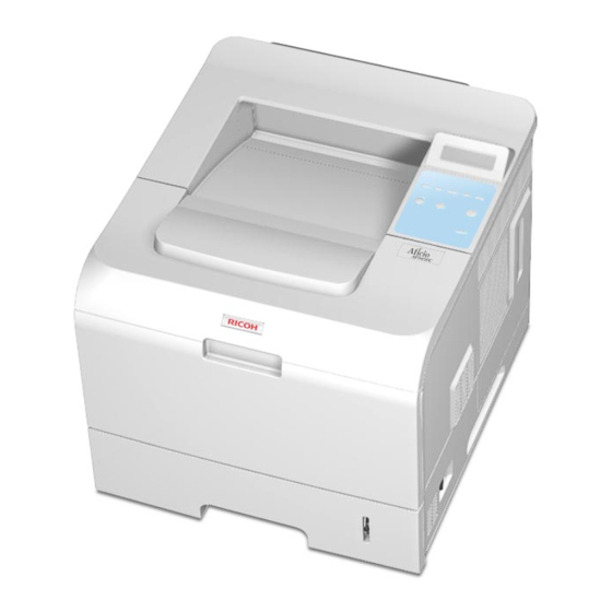
9. Paper level indicator 3. Control board cover 10. By-pass tray 4. Tray 1 11. Top cover 5. Optional tray 2 12. By-pass tray paper width guides 6. Optional tray 3 13. By-pass tray extension 7. Optional tray 4 G186... -
Page 140: Rear View
Printer Components 6.1.2 REAR VIEW g186d507 1. Power switch 5. Parallel port 2. Rear cover 6. USB port 3. Duplex unit 7. Network port 1 4. Power receptacle G186... -
Page 141: System Layout
(envelopes, labels, and special paper), duplex unit, and various paper transfer parts. Separation method Separation is achieved by a friction pad mounted in the center of the cassette and stopper roller that uses a spring clutch. A feed roller uses an electronic clutch to control driving power. G186... -
Page 142: Basic Cassette
Consisting of PTL (Pre-transfer Lamp) and transfer roller. A PTL throws light on the OPC drum, lowers the electric potential of the OPC drum's surface, and improves the efficiency of the transfer. A transfer roller transfers toner on an OPC drum to the paper. G186... -
Page 143: Drive
80°C to avoid burns. 6.2.5 LSU (LASER SCANNER UNIT) The LSU is the core part of this laser beam printer which switches from the video data received to the controller to the electrostatic latent image on the OPC drum by controlling G186... -
Page 144: Print Cartridge
Toner: Non magnetic, one component pulverized type toner Toner life span: 150 K (LSA Pattern/A4 standard) Remaining Toner Sensor: Yes OPC Cleaning: Cleaning blade type Management of waste toner: Toner collection by Cleaning Blade OPC Drum protecting Shutter: Yes Classifying device for toner cartridge G186... -
Page 145: Engine Hardware Specifications
Asic (ORION 2) Marvell Feroceon 2850 ARM Compatible (I-Cache: 32KB, D-Cache-32KB) 64-bit RISC embedded processor core Dual bus architecture for bus traffic distribution - AMBA High performance Bus (AHB) - System Bus with SDRAM G186... -
Page 146: Memory
Memory NOR Flash Memory: It stores System Program and downloads the System Program through PC Interface, and in case of export models, it compresses the PCL font, then stores it. - Capacity: 128M Byte - Access Time: 70 nsec G186... -
Page 147: Others
The Paper empty sensor (Photo Interrupter) on the engine board transmits a “paper drawer empty” signal to the CPU when there is no paper, triggered by the actuator. The empty condition - read from the D0 part of the CPU. G186... -
Page 148: Paper Sensing On The By-Pass Tray
The motor driving circuit is formed when the Driver IC is selected in the first place. The A3977 Motor Driver IC is used in this case. But the resistance Rs value of sensing and the voltage value of the V reference can be changed by motor driving voltage value. The motor G186 6-10... -
Page 149: Smps & Hvps Board
- Fluctuating transfer voltage with environmental various: +650 V(Duty 10%) to 5 KV (Duty 90%) - Environment Recognition Control Method: The THV-PWM ACTIVE is the transfer active signal. It detects the resistance by recognizing the voltage value, F/B, while 6-11 G186... - Page 150 - Output Voltage Rising Time: 50 ms Max - Output Voltage Falling Time: 50 ms Max - Output Loading range: 10 M to 1000 M - Output Control Signal (BIAS-PWM): the CPU is HV output when PWM is low. G186 6-12...
-
Page 151: Smps (Switching Mode Power Supply)
4.0 A 7.5 A Peak Loading Current 4.4 A 8.0 A ROPPLE NOISE Voltage Under 100 mVp-P Under 100 mVp-P Maximum output 16.0 W 127.2 W Peak output 20.0 W 180.0 W Protection for loading shortage and overflowing current 6-13 G186... -
Page 152: Fuser Ac Power Control
AC current flows in the heat lamp, and heat occurs. On the other hand, when the signal is off, the PC1 is off, the voltage is cut off at the gate of Triac, the Triac becomes off, and then the heat lamp is turned off. G186 6-14... -
Page 153: Engine Firmware
After the leading edge of the paper has passed the feed sensor, the JAM 1 paper does not reach the exit sensor for a certain time. (The exit sensor does not turn on.) *This status means that the paper exists between the feed sensor and the exit sensor. 6-15 G186... -
Page 154: Driver
AC power is controlled by comparing the target temperature to the value from the thermistor. If the value from the thermistor is out of controlling range while controlling the fusing, the error stated in the below table occurs. G186 6-16... -
Page 155: Lsu
Hsync occurs. Error messages are as follows: Error Description LCD Display Polygon Motor When the polygon motor speed does not "LSU NOT READY" Error become steady. LOW HEAT The polygon motor speed is steady but "HSYNC ERROR" ERROR Hsync is not generated. 6-17 G186... -
Page 157: Specifications
SPECIFICATIONS... -
Page 159: General Specifications
Warm-up Time 45 seconds from Power-on boot Power Rating 110 - 127 VAC or 220 - 240 VAC Average: Less than 650 W Power Consumption Power save mode: Less than 13 W Noise Level Standard mode: Less than 35 dBA G186... - Page 160 Dimension (W x D x H) 396 X 453 X 353 mm (15.6" X 17.8" X 13.9") Weight 17.8 Kg (39.2 lb); including consumables 7.1.2 OPTION Item Memory 512MB (maximum - accepts 128MB & 256MB boards) Optional Tray 500 sheet Cassette Tray G186...
-
Page 161: Controller
Server(32/64bits) Netware 4.x, 5.x, 6.x Network Mac OS 8.6~9.2, 10.1~10.4 Supporting OS Various Linux OS including Red Hat 8.0 to 9.2, Fedora Core 1~3, Mandrake 9.2~10.1 and SuSE 8.2~9.2 Interface IEEE 1284, High Speed USB 2.0, 10/100 Base TX G186... -
Page 162: Handling Paper
Media weight 16 to 28 lb (60 to 105 g/m Sensing Paper empty sensor, Paper Size Sensor Media sizes A4, Letter, Legal, Folio, Oficio Optional Duplex Media types Plain Paper Media weight 20 to 24lb (75 to 90 g/m G186... -
Page 163: Appendix
APPENDIX... -
Page 165: Block Diagram
Block Diagram 8. APPENDIX 8.1 BLOCK DIAGRAM 8.1.1 SYSTEM BLOCK DIAGRAM G186... - Page 166 Block Diagram G186...
-
Page 167: Connection Diagram
Connection Diagram 8.2 CONNECTION DIAGRAM G186... -
Page 168: Signal Description Table
Signal Name Signal Name ← DEVE_AC-PWM ← ← DEVE_AC_Vpp ← ← DEVE_AC_CON ← ← DEVE_VDC-PWM ← 24VS ← FUSER_BIAS_PWM ← 3.3V ← MHV_PWM ← 3.3V ← FAN_SMPS ← 3.3V ← THV_PWM ← ← THV_READ ← ← nTHV_EN ← FAN_FEEDBACK G186... -
Page 169: Cn19 [Duplex] Main ↔ Duplex B'd
← ← ↔ CN19 [DUPLEX] MAIN DUPLEX B'D Signal Name Signal Name ← 24VS ← 3.3V ← 3.3V ← DUPLEX_RXD DUPLEX_DETECT GND (DETECT) ← DUPLEX_TXD ← ← ← ↔ CN20 [EXIT SENSOR] MAIN EXIT SENSOR Signal Name Signal Name G186... -
Page 170: Cn24 [Dc_Mot] Main ↔ Main Motor
CN24 [DC_MOT] MAIN MAIN MOTOR Signal Name Signal Name ← 24VS ← 24VS ← ← ← ← ← nMAIN_MOT ← MAIN_MOT_READY ← MAIN_MOTCLK ↔ CN25 [JOINT] MAIN JOINT B'D Signal Name Signal Name ← 24VS ← MAIN_CLUTCH ← BYPASS_CLUTCH ← REGI_CLUTCH G186... -
Page 171: Cn22 [Dev_Mot] Main ↔ Deve Motor
← 3.3V ← CASSETTE_DETECT ← ← TEMP1 ↔ CN22 [DEV_MOT] MAIN DEVE MOTOR Signal Name Signal Name ← 24VS ← ← nDEV_MOT_READY ← nDEV_MOT_CLK ← nDEV_MOT_ON ← nDEV_MOT_DIR ↔ CN23 [PTL] MAIN Signal Name Signal Name ← ← PTL_ON G186... -
Page 172: Cn18 [Panel] Main ↔ Panel
PANEL Signal Name Signal Name ← ← 3.3V ← PANEL_TXD ← PANEL_RXD ← nRSTOUT ← ↔ CN15 [COVER OPEN] MAIN COVER OPEN Signal Name Signal Name ← ← ← 24VS ← 24VS ← ← COVE_OPEN ← ← ← LSU_5V G186... -
Page 173: Cn13 [Dpx_Sol] Main ↔ Duplex Solenoid
24VS ↔ CN9 [LSU] MAIN Signal Name Signal Name ←(LD DRIVER) ← LSU_5V ← LD_POWER2 ← LD_POWER1 ← VDO1_minus ← VDO1_plus ← VDO2_minus ← VDO2_plus ← nLD_EN ← nSH1 ← nHSTNC_plus ← nSH2 ← nHSTNC_minus ←(P-MOTOR) LSU_CLK ← nREADY G186... -
Page 174: Cn4 [Cart] Main Toner Sensor
← ← ↔ CN4 [CART] MAIN TONER SENSOR Signal Name Signal Name ← ← P_SIZE3 ← FAN_SMPS ← P_SIZE2 ← FAN_MAIN ← P_SIZE1 ← ← 3.3V ← OUTBIN_FULL ← CART_CLK ← P_REGI ← CART_DOUT/CART_DIN ← P_EMPTY ←(P-MOTOR) LSU_CLKGND G186 8-10... -
Page 175: Cn17 [Scf] Main ↔ Scf B'd
CN17 [SCF] MAIN SCF B'D Signal Name Signal Name ← ← 3.3V SCF_EMPTY 3.3V ← SCF_RXD ← SCF_DETECT ← SCF_TXD ← ← ← ← ← ↔ CN8 [THERM] MAIN FUSER Signal Name Signal Name ← THERM_IN FUSER_ON FUSER_EN FUSER_ON 8-11 G186...
Need help?
Do you have a question about the G186 and is the answer not in the manual?
Questions and answers