
Related Manuals for Poindus VariPOS-815


Summary of Contents for Poindus VariPOS-815
- Page 1 User Manual Version V1.1 FEB. 2012 VariPOS™ -815 © Copyright Poindus Systems 2011 P1 / 50...
- Page 2 TRADEMARK ® Poindus / VariPOS are registered trademarks of Poindus Systems. ® ® ® ® Intel / Core i3 / i5 are registered trademarks of Intel Corporation.
- Page 3 There is a danger of explosion if the battery is replaced incorrectly. Replace only with the same or equivalent type recommended by the manufacturer. Discard used batteries according to the manufacturer’s instructions. © Copyright Poindus Systems 2011 P3 / 50...
-
Page 4: Table Of Contents
4-7 Install the Metal Stand ..........22 4-8 Install the Wall Mount Kits ........23 Jumper Settings 5-1 Motherboard Layout (Intel Sandy Bridge CPU) ..24 Serial Port Pin 9 Mode Settings Spare parts List Appendix © Copyright Poindus Systems 2011 P4 / 50... -
Page 5: Packing List
1 Packing List 1-1 Standard items 【 【 【 【 VariPOS -815】 】 】 】 ™ ™ ™ ™ Power adapter System Power cord Driver bank CD © Copyright Poindus Systems 2011 P5 / 50... -
Page 6: Accessory Items
*1: There are security screws and a screw driver for replacing the hard drive fixing screw. Customers can use the security screws to ensure HDD security. *2: VGA Cable is only for I/O interface with VGA port. © Copyright Poindus Systems 2011 P6 / 50... -
Page 7: System Overview
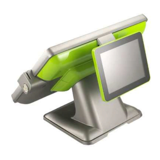
2 System Overview 【 【 【 【 VariPOS-815】 】 】 】 © Copyright Poindus Systems 2011 P7 / 50... -
Page 8: I/O Interface
2-1 I/O Interface 【 【 【 【 Standard Version】 】 】 】 【 【 【 【 VGA Version】 】 】 】 © Copyright Poindus Systems 2011 P8 / 50... -
Page 9: Specification
Audio Port 1 x Line-out ; 1 x Mic-In PS/2 Port 1 x PS/2 connector for Keyboard LPT Port 1 x DB-25 Printer Port (Standard) VGA Port 1 x DB-15 VGA Port (Optional) © Copyright Poindus Systems 2011 P9 / 50... - Page 10 Operating Temperature 0ºC ~ 40ºC, 10% ~ 90% RH, non-condensing Storage Temperature -20ºC ~ 60ºC, 10% ~ 90% RH, non-condensing *The right has been reserved to change the specification without prior notice. © Copyright Poindus Systems 2011 P10 / 50...
-
Page 11: System Assembly & Disassembly
3. Release the screws of hinge cover 4. Remove the plastic hinge cover parts 5. Release the screws of base 6. Open the plastic cover from two sides 7. Release the screws of aluminium back frame © Copyright Poindus Systems 2011 P11 / 50... - Page 12 © Copyright Poindus Systems 2011 P12 / 50...
-
Page 13: Replace The Hdd
5. Screw 4 x round screws on the HDD tray and insert the HDD tray into the whole system HDD slot 6. Fix HDD tray on the system with the 1x screw © Copyright Poindus Systems 2011 P13 / 50... - Page 14 3SMUH30061N0 ROUND WASHER HEAD SCREWS:m3*0.5-6MM,NI Security Screws* * There are security screws and a screw driver enclosed in product carton. * Customers can use the special security screws to ensure HDD security. © Copyright Poindus Systems 2011 P14 / 50...
-
Page 15: Install A Customer Display
3. Connect the customer display into COM3 via the cable management slot and adjust COM3 voltage to +12V in BIOS (refer to Chapter 6) 4. Fasten the IO cover into the right position and turn the system on the right position. © Copyright Poindus Systems 2011 P15 / 50... -
Page 16: Install A Second Display
4-4 Install a Second Display 1. Slide the 2 display hinge into the hinge holder on VariPOS. 2. Tighten the 4 screws that attached in the accessory box. © Copyright Poindus Systems 2011 P16 / 50... - Page 17 3. Plug the VGA cable to VGA port on the terminal. 4. Don’t forget to insert the I/O cover. 5. Done © Copyright Poindus Systems 2011 P17 / 50...
- Page 18 2. Connect the extension VGA cable enclosed with the accessory box to the VGA cable of the external monitor. 3. Plug the extension VGA cable to VGA port and install the I/O cover back to finish the installation. © Copyright Poindus Systems 2011 P18 / 50...
-
Page 19: Install A Cash Drawer
BIT2 BIT1 BIT0 Attribute Write Write Reserved Reserved Read Cash Drawer “DIN bit0” pin input status Reserved Reserved Cash Drawer “DOUT bit0” pin output control Cash Drawer “DOUT bit1” pin output control © Copyright Poindus Systems 2011 P19 / 50... - Page 20 Cash Drawer I A24 Check status The I/O address A24h bit0 =0 mean the Cash Drawer is opened or not exist. The I/O address A24h bit0 =1 mean the Cash Drawer is closed. © Copyright Poindus Systems 2011 P20 / 50...
-
Page 21: Install The Msr & Ibutton Reader
1. Open the right side cover of system. * MSR connection is supported on the right side 2. Connect MSR to System connector, system connector supports PS/2 and RS-232 interface. 3. Fasten the MSR screw on system MSR: RS-232 Interface System connector supports PS/2 and RS-232 interface © Copyright Poindus Systems 2011 P21 / 50... -
Page 22: Install The Metal Stand
4-7 Install the Metal Stand Power & VFD Cable Management © Copyright Poindus Systems 2011 P22 / 50... -
Page 23: Install The Wall Mount Kits
4-8 Install the Wall Mount Kits © Copyright Poindus Systems 2011 P23 / 50... -
Page 24: Jumper Settings
5 Jumper Settings 5-1 Motherboard Layout (Sandy Bridge ) © Copyright Poindus Systems 2011 P24 / 50... - Page 25 IVT1 Inverter Connector FAN1 CPU Fan Connector FAN2 System Fan Connector LED2 LED Connector DIO1 Digital Input / Output Connector HDMI1 HDMI Connector DisplayPort Connector Clear CMOS SATA Power Enable for SATA4 © Copyright Poindus Systems 2011 P25 / 50...
- Page 26 PIN5 PIN6 +5V_PS2 SPWR1 / 2 / 3 : Power Output for SATA HDD PIN1 +5V_HDD PIN2 PIN3 PIN4 +12V_HDD IVT1 : Inverter Connector PIN1 PIN2 IVT_PWM PIN3 BKL_EN PIN4 PIN5 +12V_IVT © Copyright Poindus Systems 2011 P26 / 50...
- Page 27 PIN5 BLUE_CRT PIN6 PIN7 HSYNC_CRT PIN8 PIN9 VSYNC_CRT PIN10 AUD2 : Speaker Out Connector PIN1 LINE_OUT_R+ PIN2 LINE_OUT_R- PIN3 LINE_OUT_L- PIN4 LINE_OUT_L+ MIC2 : MIC In Connector PIN1 MIC_IN_L PIN2 PIN3 MIC_IN_R © Copyright Poindus Systems 2011 P27 / 50...
- Page 28 TOUCH1 : 5W Resistive Touch Panel Connector PIN1 PIN2 PIN3 PROBE PIN4 PIN5 PW1 : Power Button PIN1 Power Button+ PIN2 Power Button- PW3 : Power Button Connector PIN1 Power Button+ PIN2 Power Button- © Copyright Poindus Systems 2011 P28 / 50...
- Page 29 SJ1 : Clear CMOS Setup JCLR1 Description Clear CMOS Normal operation SJ2 : SATA Power Enable for SATA4(6) Description 5V SATA Power Enable Normal operation SJ2 setting SATA4(6) pin7 is GND or 5V. © Copyright Poindus Systems 2011 P29 / 50...
-
Page 30: Serial Port Pin 9 Mode Settings
When the BIOS Main Menu is displayed, the following items can be selected. Use the arrow keys to select items and the enter key to accept and enter the sub-menu. Enter System Overview Advanced Settings Use this menu for set up super IO configuration. © Copyright Poindus Systems 2011 P30 / 50... - Page 31 Select Super IO Configuration Serial Port 1-4 Pin9 Mode Enter into serial port 1- 4 Pin9 Mode and set up the options. Select the serial port 1 Pin9 mode. Save and Exit © Copyright Poindus Systems 2011 P31 / 50...
-
Page 32: Spare Parts List
ASS'Y,PP01 SPARE PARTS: TOUCH PANEL CAPACITIVE(WHITE) XTOUCHCW0010 ASS'Y,PP01 SPARE PARTS: TOUCH PANEL RESISTIVE(BLACK) XTOUCHRB0010 ASS'Y,PP01 SPARE PARTS: TOUCH PANEL RESISTIVE(WHITE) XTOUCHRW0010 ASS'Y,PP01 SPARE PARTS: PCT TOUCH CONTROLER with PLASTIC XTCONTROL010 SCREW ASS'Y,PP01 © Copyright Poindus Systems 2011 P32 / 50... - Page 33 HEATSINK W/thermal pad, FOR VARI POS/PPC 815 3XMC00000080 RAM Modular HEATSINK W/thermal pad 6PN115052110 LCD PANEL: AUO , 15" TFT, 1024x768 6PN117001710 LED PANEL FOR 2 DISPLAY 61V205510400 INVERTER:DUAL LAMP 5.5mA PLCD1715204BE © Copyright Poindus Systems 2011 P33 / 50...
- Page 34 6CR000000010 MSR Module RS232 6CR000000020 MSR Module PS2 6CR842000000 I-BUTTON READER MODULE FINGERPRINT: USB FINGERPRINT READER MODULE 6PP000000030 50012-0H1-103 6PP000000020 MIFARE SECTOR READER ((MF10U-PD) 6LN050000010 WIRELESS 802.11 b/g/n USB © Copyright Poindus Systems 2011 P34 / 50...
- Page 35 RAM: 4G DDRIII 1333MHz 204P,BRAND:HYNIX 6RMS04G48A10 (256Mx8*16) 6RMS02G48A10 RAM: 2G DDRIII 1333MHz 204P,BRAND:HYNIX (256Mx8*8) 2UCPUCELB810 INTEL CPU : Celeron B810 2UCPUI32330M INTEL CPU : i3 2330E 2UCPUI52510E INTEL CPU : i5 2510E © Copyright Poindus Systems 2011 P35 / 50...
- Page 36 VFD BOARD: W/FUTABA/10P8C(COM) V1.0 52F008V10006 Cable: 3CW000000740 VFD BOARD: PE02 V1.0 52FVFDV1000D Cable: 3CW000000150 52ADB0000010 AD BOARD FOR 2 DISPLAY 6PWA1204C000 POWER ADAPTER: DC12V/10A EA11353A-120(25) 3CP000000050 POWER CORD (Brazil) TO MINI 3P © Copyright Poindus Systems 2011 P36 / 50...
- Page 37 POWER CORD (EU) TO MINI 3P LCD CABLE: A1255-H P=1.25 2x15pin female, A1253-H 3CW000000530 P=1.25 20pin female, 260mm VGA CABLE: internal VGA cable with power connecter 3CW000000521 D-SUB15PIN male, DuPont2.54, 2*5PIN+JST 2.0 4PIN,140mm, © Copyright Poindus Systems 2011 P37 / 50...
- Page 38 MSR extend cable: MOLEX P=1.25 15pin female, MOLEX 3CW000000560 P=1.25 15pin female, 150mm USB cable: JST P=2.0 5pin female, MOLEX P=1.25 4pin 3CW000000090 female, 320mm 3CW000000050 LPT cable: DuPont P2.0 2x13pin female, DB25, 1600mm © Copyright Poindus Systems 2011 P38 / 50...
- Page 39 3CW000000180 DC 5.5-2.5, D-SUB15PINfemale, 300mm 3CW000000300 3 in 1 cable: for MSR, Finger printer and I-Button 3CW000000310 3 in 1cable: for MSR+RFID only Extend VGA cable:DS-UB15PIN female,D-SUB15PIN 3CW000000190 female,110mm, W/O power pin © Copyright Poindus Systems 2011 P39 / 50...
- Page 40 3CMD9MJT0100 COM3 CABLE: RJ45/DB9 3P00040B0600 LCD SIDE COVER: Gray 3P00040E0400 LCD SIDE COVER: White 3P00040B0200 LCD SIDE COVER: Black 3P00050D0200 HINGE COVER: Black © Copyright Poindus Systems 2011 P40 / 50...
- Page 41 3P00050D0600 HINGE COVER: Gray 3P00050F0400 HINGE COVER: White 3P00050D1000 HINGE COVER: Green 3P00050D0800 HINGE COVER: Red 3P00032D0800 PPC I/O cover: Red © Copyright Poindus Systems 2011 P41 / 50...
- Page 42 3P00032D0600 PPC I/O cover: Gray 3P00032F0400 PPC I/O cover: White 3P00032D1000 PPC I/O cover: Green 3P0003D0200 PPC I/O cover: Black 3P00030D0610 POS I/O cover w/o VFD: Gray © Copyright Poindus Systems 2011 P42 / 50...
- Page 43 POS I/O cover w/o VFD: Red 3P00030D1010 POS I/O cover w/o VFD: Green 3P00030F0410 POS I/O cover w/o VFD: White 3P00030D0210 POS I/O cover w/o VFD: Black 3P00031D0610 POS I/O cover W/VFD: Gray © Copyright Poindus Systems 2011 P43 / 50...
- Page 44 3P00031D0810 POS I/O cover W/VFD: Red 3P00031D1010 POS I/O cover W/VFD: Green 3P00031F0410 POS I/O cover W/VFD: White 3P00031D0210 POS I/O cover W/VFD: Black 3P00060D0600 VFD cover: Gray © Copyright Poindus Systems 2011 P44 / 50...
- Page 45 3P00060D0800 VFD cover: Red 3P00060D1000 VFD cover: Green 3P00060F0400 VFD cover: White 3P00060D0200 VFD cover: Black 3P00090D0600 display rear cover: Gray © Copyright Poindus Systems 2011 P45 / 50...
- Page 46 3P00090D0800 display rear cover: Red 3P00090D1000 display rear cover: Green 3P00090F0400 display rear cover: White 3P00090D0200 display rear cover: Black 3P00070P0910 VFD LENS © Copyright Poindus Systems 2011 P46 / 50...
- Page 47 3P00110K0200 display LENS: Black 3P00110K0400 display LENS: White © Copyright Poindus Systems 2011 P47 / 50...
-
Page 48: Appendix
4. At the Windows 7 Operation System environment, when customer want to use PCT touch multi-touch it is not required to install the touch driver. 5. Resistive touch is RS232 interface (COM6) and the PCT touch is USB interface. © Copyright Poindus Systems 2011 P48 / 50... - Page 49 6. Calibration with EETI touch utility: please into “tool” page and press “4 Points Calibration”. 7. Calibration in WIN7: Control panel Hardware and Sound Tablet PC setting Calibrate the screen from pen or touch input © Copyright Poindus Systems 2011 P49 / 50...
- Page 50 Version Change History: : : : Version Change Date Change Content V1.0 October, 2011 Release V1.1 Feb, 2012 Upgrade spare parts © Copyright Poindus Systems 2011 P50 / 50...
Need help?
Do you have a question about the VariPOS-815 and is the answer not in the manual?
Questions and answers