
Related Manuals for Poindus VariPOS 250


Summary of Contents for Poindus VariPOS 250
- Page 1 User Manual Version V1.0 May. 2018 VariPOS™ 250 © Copyright Poindus Systems 2012 P1 / 23...
-
Page 2: Table Of Contents
Install the Customer display---------------------------------------------------------------------------15 Install the MSR------------------------------------------------------------------------------------------15 Power configuration of COM ports--------------------------------------------------------------------16 Install the Cash drawer--------------------------------------------------------------------------------17 Motherboard information (PE20) -----------------------------------19 Motherboard Layout------------------------------------------------------------------------------------19 Connectors & Jumper Settings------------------------------------------------------------------------ Motherboard information (PE21) -----------------------------------21 Motherboard Layout------------------------------------------------------------------------------------21 © Copyright Poindus Systems 2012 P2 / 23... -
Page 3: Notices
Proprietary information contained in this document is copyright protected. Photocopying, producing or translating this document or any part of it without obtaining a written consent from Poindus is prohibited. Changes in this document or in the products described herein may be made without prior notice. Incidental or consequential damage/s related to the use of this document is not Poindus liability. -
Page 4: Safety Information
8) If there is smoke or strange smell, unplug the power cord from the power outlet immediately and request repair from your dealer or POINDUS. This device complies with the requirements of the VariPOS directive 2004/108/EC with regard to “Electromagnetic compatibility”. -
Page 5: Ce Verification
© Copyright Poindus Systems 2012 P5 / 23... -
Page 6: Fcc Verification
© Copyright Poindus Systems 2012 P6 / 23... -
Page 7: Welcome
Welcome Congratulations on your purchase of VariPOS/VariPPC. The following illustration displays the package contents of your new product. If any of the following items is damaged or missing, please contact Poindus. Package contents 【 VariPOS 250 】 ™ VariPOS250 Power adapter... -
Page 8: Getting To Know Your Varipos250
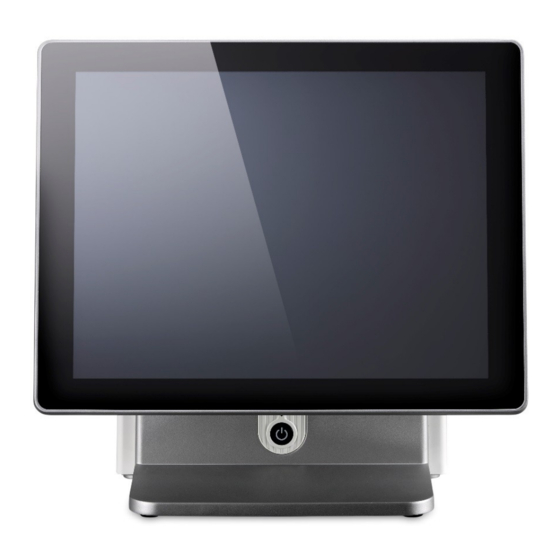
Getting to know your VariPOS250 Front view True flat touch panel Die-casting aluminum base *all peripherals are depends on customer’s demand © Copyright Poindus Systems 2012 P8 / 23... -
Page 9: Rear View
Rear view I/O interface 【VariPOS250】 © Copyright Poindus Systems 2012 P9 / 23... -
Page 10: Specification
I/O Ports (Broadside) Power Switch 1 x power on/off switch button System Management Win10 2016 (32/64bit), Win8.1 (32/64bit), Win10 2016 (64bit), Win8.1 (64bit), Win7/POS OS Support Win7/POS Ready 7 (32/64bit) Ready 7 (32/64bit) © Copyright Poindus Systems 2012 P10 / 23... - Page 11 1. PE21 : TPM feature only available for UEFI BIOS (Standard BIOS). If user select Legacy BIOS (Optional) this feature will be disabled. 2. PE21 : Win10 64bit and Win8.1 64ibt will use UEFI BIOS and Legacy BIOS is for Win7 (32/64bit) only. *Poindus reserves the right to change the specification without prior notice. © Copyright Poindus Systems 2012...
-
Page 12: Uefi Bios And Legacy Bios Settings (Pe21)
UEFI BIOS and Legacy BIOS settings (PE21) © Copyright Poindus Systems 2012 P12 / 23... - Page 13 UEFI BIOS © Copyright Poindus Systems 2012 P13 / 23...
- Page 14 Legacy BIOS © Copyright Poindus Systems 2012 P14 / 23...
-
Page 15: System Assembly & Disassembly
System Assembly & Disassembly Install a Customer Display and 2 display Install MSR module © Copyright Poindus Systems 2012 P15 / 23... -
Page 16: Power Configuration Of Com Ports
Power configuration for COM PORTS © Copyright Poindus Systems 2012 P16 / 23... -
Page 17: Install The Cash Drawer
Write Reserved Read Write Read Reserved Reserved Cash Drawer “DIN0” Cash Drawer “DOUT1” Pin output control Cash Drawer “DIN1” Pin output control Pin output control Reserved Cash Drawer “DOUT0” Pin output control © Copyright Poindus Systems 2012 P17 / 23... - Page 18 I 482 The status of cash drawer The I/O address 482h bit3 =1 (Cash Drawer is opened or not exist) The I/O address 482h bit3 =0 (Cash Drawer is closed) © Copyright Poindus Systems 2012 P18 / 23...
-
Page 19: Motherboard Information (Pe20)
Motherboard information Motherboard Layout (PE20) © Copyright Poindus Systems 2012 P19 / 23... -
Page 20: Connectors & Jumper Settings
COM4 : Pin Header for COM4 Port PIN1 PIN2 PIN3 PIN4 PIN5 PIN6 PIN7 PIN8 PIN9 PIN1 JP1 : Clear CMOS Setup Description Normal operation Clear CMOS JP2 : Cash Drawer Voltage Setup Description +19V +12V © Copyright Poindus Systems 2012 P20 / 23... -
Page 21: Motherboard Information (Pe21)
Motherboard Layout (PE21) © Copyright Poindus Systems 2012 P21 / 23... - Page 22 COM4 : Pin Header for COM4 Port PIN1 PIN2 PIN3 PIN4 PIN5 PIN6 PIN7 PIN8 PIN9 PIN1 JP1 : Clear CMOS Setup Description Normal operation Clear CMOS JP2 : Cash Drawer Voltage Setup Description +19V +12V © Copyright Poindus Systems 2012 P22 / 23...
- Page 23 Version Change History Version Change Date Change Content V1.0 May. 2018 release © Copyright Poindus Systems 2012 P23 / 23...
Need help?
Do you have a question about the VariPOS 250 and is the answer not in the manual?
Questions and answers