
Related Manuals for Poindus VariPOS 715S


Summary of Contents for Poindus VariPOS 715S
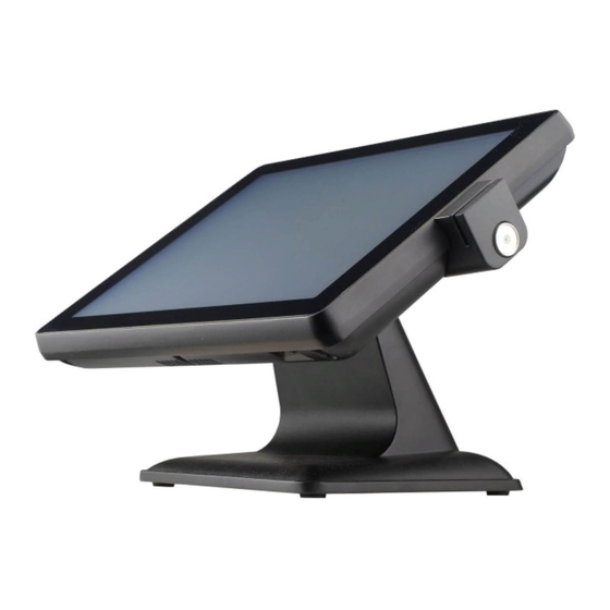
- Page 1 User Manual Version V1.1 Jul. 2014 VariPOS™ 715S © Copyright Poindus Systems 2012 P1 / 34...
-
Page 2: Table Of Contents
How to configure the 2 display resolution---------------------------------------------------------25 Install the cash drawer---------------------------------------------------------------------------------27 Install the MSR & I-Button Reader--------------------------------------------------------------------29 Install the Die-casting aluminum base---------------------------------------------------------------30 Motherboard information---------------------------------------------31 Motherboard Layout------------------------------------------------------------------------------------31 Connectors & Jumper Settings------------------------------------------------------------------------32 Spare parts list---------------------------------------------------------33 Version Change History-----------------------------------------------35 © Copyright Poindus Systems 2012 P2 / 34... -
Page 3: Notices
Proprietary information contained in this document is copyright protected. Photocopying, producing or translating this document or any part of it without obtaining a written consent from Poindus is prohibited. Changes in this document or in the products described herein may be made without prior notice. Incidental or consequential damage/s related to the use of this document is not Poindus liability. -
Page 4: Safety Information
8) If there is smoke or strange smell, unplug the power cord from the power outlet immediately and request repair from your dealer or POINDUS. This device complies with the requirements of the VariPOS directive 2004/108/EC with regard to “Electromagnetic compatibility”. - Page 5 © Copyright Poindus Systems 2012 P5 / 34...
- Page 6 © Copyright Poindus Systems 2012 P6 / 34...
-
Page 7: Welcome
Welcome Congratulations on your purchase of VariPOS715S. The following illustration displays the package contents of your new product. If any of the following items is damaged or missing, please contact Poindus. Package contents 【 VariPOS 715S ™ 】 VariPOS Power adapter... -
Page 8: Getting To Know Your Varipos715S
Getting to know your VariPOS715S Front view Customer display* (VFD) True flat touch panel Resistive/PCT Peripheral *(RFID/I-Button/MSR/FP) Die-casting aluminum base *all peripherals are depends on customer’s demand © Copyright Poindus Systems 2012 P8 / 34... -
Page 9: Rear View
Rear view *all peripherals are depends on customer’s demand I/O interface 【Standard Version】 © Copyright Poindus Systems 2012 P9 / 34... -
Page 10: Using The Touch Screen
1. Calibration with touch utility in WINXP/WIN7 for Resistive touch: please click the icon as picture below for “4 Points Calibration”. 2. If you need further configuration please click “Advanced” 3. If you use the PCT touch panel, please refer to below picture to calibration in WIN7. © Copyright Poindus Systems 2012 P10 / 34... - Page 11 • Spray a small amount of a household glass cleaner onto the supplied cleaning cloth and gently wipe the screen surface. • Do not spray the cleaner directly on the screen. (Resistive touch panel only) • Do not use an abrasive cleaner or a coarse cloth when cleaning the screen. © Copyright Poindus Systems 2012 P11 / 34...
-
Page 12: Usb3.0 Installation And Enable
Step2: XHCI mode [Disable] and EHCI Controller [Enable] then install Windows 7. Step3: After installation Windows 7 is done, select BIOS XHCI mode to [Smart Auto]. Step4: Install USB 3.0 driver in windows 7. © Copyright Poindus Systems 2012 P12 / 34... - Page 13 Step4-1: Install driver done. Step5: When install USB 3.0 driver is done, adjust BIOS XHCI mode [Enable] and EHCI Controller [Disable]. Follow above steps now your USB 3.0 work well in Windows 7. © Copyright Poindus Systems 2012 P13 / 34...
-
Page 14: Specification
1 x Gigabit Ethernet by RJ-45 USB Port 4 x USB 2.0/ 1 x USB3.0 Serial Port 3 x RS-232(RJ48 connector) COM1/COM2/COM3 Pin9 w/RI/5V/12V Selectable by BIOS (default is RI) VGA Port 1 x DB-15 VGA Port © Copyright Poindus Systems 2012 P14 / 34... - Page 15 100 x 100mm Operating Temperature 0ºC ~ 40ºC, 10% ~ 90% RH, non-condensing Storage Temperature -20ºC ~ 60ºC, 10% ~ 90% RH, non-condensing *Poindus reserves the right to change the specification without prior notice. © Copyright Poindus Systems 2012 P15 / 34...
-
Page 16: System Assembly & Disassembly
3. Release the screws of hinge cover 4. Remove the plastic hinge cover parts 5. Release the screws of base 6. Open the plastic cover from two sides 7. Release the screws of aluminium back frame © Copyright Poindus Systems 2012 P16 / 34... - Page 17 © Copyright Poindus Systems 2012 P17 / 34...
-
Page 18: Replace The Hdd
5. Screw 4 x round screws on the HDD tray and insert the HDD tray into the whole system HDD slot 6. Fix HDD tray on the system with the 1x screw © Copyright Poindus Systems 2012 P18 / 34... - Page 19 Screw Pack Item Part No. Description Q’ty 3SMFH30042N0 F‐HEAD SCREW:M3*0.5‐4mm,NI(for HDD) 3SMPW03042M0 P‐HEAD SCREW:M3*0.5‐4mm,NI(for HDD bracket) 3SMPW03061C0 P‐HEAD SCREW:M3*0.5‐6mm,NI black(to fasten VFD) 3SMPW03081C0 P‐HEAD SCREW:M3*0.5‐8mm,NI black(to fasten 2 display) © Copyright Poindus Systems 2012 P19 / 34...
-
Page 20: Install The Customer Display
3. Connect the customer display into COM3 via the cable management slot and adjust COM3 voltage to +12V in BIOS (refer to Chapter 6) 4. Fasten the IO cover into the right position and turn the system on the right position. © Copyright Poindus Systems 2012 P20 / 34... -
Page 21: Install The Second Display
Install a Second Display 1. Slide the 2 display hinge into the hinge holder on VariPOS. 2. Tighten the 4 screws that attached in the accessory box. © Copyright Poindus Systems 2012 P21 / 34... - Page 22 3. Plug the VGA cable to VGA port on the terminal. 4. Done © Copyright Poindus Systems 2012 P22 / 34...
-
Page 23: Power Configuration For Com Ports And Vga Port
VariPRO715S Power configuration for COM PORTS and VGA PORT © Copyright Poindus Systems 2012 P23 / 34... -
Page 24: How To Configure The 2 Nd Display Resolution
How to configure 2 display resolution 1. Please access control panel“Intel GMA Driver”. The Primary Device is “Notebook” and Secondary Device is “Monitor” 2. Clone mode, the resolution for both display is 800*600 © Copyright Poindus Systems 2012 P24 / 34... - Page 25 When you order the 2 display (7” or 10.4”) please understand which product you will use. 3CW000005080: 7” 2 display VGA cable for VariPOS 3CW000005120: 7” 2 display VGA cable for VariPOS S series © Copyright Poindus Systems 2012 P25 / 34...
-
Page 26: Install The Cash Drawer
Write Reserved Read Write Read Reserved Reserved Cash Drawer “DIN0” Cash Drawer “DOUT1” Cash Drawer “DIN1” Pin output control Pin output control Reserved Pin output control Cash Drawer “DOUT0” Pin output control © Copyright Poindus Systems 2012 P26 / 34... - Page 27 I 482 The status of cash drawer The I/O address 482h bit3 =1 (Cash Drawer is opened or not exist) The I/O address 482h bit3 =0 (Cash Drawer is closed) © Copyright Poindus Systems 2012 P27 / 34...
-
Page 28: Install The Msr & I-Button Reader
1. Open the right side cover of system. * MSR connection is supported on the right side 2. Connect MSR to System connector, system connector supports PS/2 and RS-232 interface. 3. Fasten the MSR screw on system MSR: RS-232 Interface System connector supports PS/2 and RS-232 interface © Copyright Poindus Systems 2012 P28 / 34... -
Page 29: Install The Die-Casting Aluminum Base
Install the Die-casting aluminum base Power & VFD Cable Management © Copyright Poindus Systems 2012 P29 / 34... -
Page 30: Motherboard Information
Motherboard information Motherboard Layout © Copyright Poindus Systems 2012 P30 / 34... -
Page 31: Connectors & Jumper Settings
Connectors & Jumper Settings JP6: Cash Drawer Description +19V +12V © Copyright Poindus Systems 2012 P31 / 34... -
Page 32: Spare Parts List
POWER ADAPTER 65W/19V Y CABLE SATA 7P+15P(HDD) W/SCREW HOLE TO SATA 90° 3CXMS220260A W/LOCK 7P/4P P=2.5 L=345+325mm 3CW000005050 CABLE 15P(MB) TO 15P(MSR) P=1.25 L=230 3CW112051200 CABLE 12P(MB) P=1.25 TO 5P(LED BACKLIGHT), L=250 © Copyright Poindus Systems 2012 P32 / 34... - Page 33 CABLE 40P(MB) TO 20P(LCD) L=390 15" AU 24BIT 250NITS 3CWL40205700 "G150XG03 V.0" CABLE+SWITCH 2P TO ROCK SWITCH 2P L=400 ATX 3CWS02SW1201 POWER 3XWK2W14001A SPEAKER 2W/8Ω 80db W/CABLE 6P P=1.25 L=450mm 3CMD9MJT0100 CABLE DB9(M) TO 10P(RJ-45)+NUT SERIAL L=250 © Copyright Poindus Systems 2012 P33 / 34...
-
Page 34: Version Change History
Version Change History Version Change Date Change Content V1.0 Jul, 2014 Release V1.1 Jul, 2015 Add dual cash drawer function © Copyright Poindus Systems 2012 P34 / 34...
Need help?
Do you have a question about the VariPOS 715S and is the answer not in the manual?
Questions and answers