
Related Manuals for Poindus VariPOS 815


Summary of Contents for Poindus VariPOS 815
- Page 1 User Manual Version V2.1 Dec. 2012 VariPOS™ 815 © Copyright Poindus Systems 2012 P1 / 54...
-
Page 2: Table Of Contents
Install the cash drawer---------------------------------------------------------------------------------30 Install the MSR & I-Button Reader--------------------------------------------------------------------32 Install the Die-casting aluminum base---------------------------------------------------------------33 Install the Wall Mount kits-----------------------------------------------------------------------------34 Motherboard information---------------------------------------------35 Motherboard Layout------------------------------------------------------------------------------------35 Connectors & Jumper Settings------------------------------------------------------------------------36 Spare parts list---------------------------------------------------------38 Version Change History-----------------------------------------------54 © Copyright Poindus Systems 2012 P2 / 54... -
Page 3: Notices
Proprietary information contained in this document is copyright protected. Photocopying, producing or translating this document or any part of it without obtaining a written consent from Poindus is prohibited. Changes in this document or in the products described herein may be made without prior notice. Incidental or consequential damage/s related to the use of this document is not Poindus liability. -
Page 4: Safety Information
8) If there is smoke or strange smell, unplug the power cord from the power outlet immediately and request repair from your dealer or POINDUS. This device complies with the requirements of the VariPOS directive 2004/108/EC with regard to “Electromagnetic compatibility”. -
Page 5: Ce Verification
© Copyright Poindus Systems 2012 P5 / 54... -
Page 6: Fcc Verification
© Copyright Poindus Systems 2012 P6 / 54... -
Page 7: Welcome
Welcome Congratulations on your purchase of VariPOS/VariPPC. The following illustration displays the package contents of your new product. If any of the following items is damaged or missing, please contact Poindus. Package contents 【 VariPOS 815 】 ™ VariPOS Power adapter... -
Page 8: Accessory Items
*1: There are security screws and a screw driver for replacing the hard drive fixing screw. Customers can use the security screws to ensure HDD security. *2: VGA Cable is only for I/O interface with VGA port. © Copyright Poindus Systems 2012 P8 / 54... -
Page 9: Getting To Know Your Varipos/Varippc
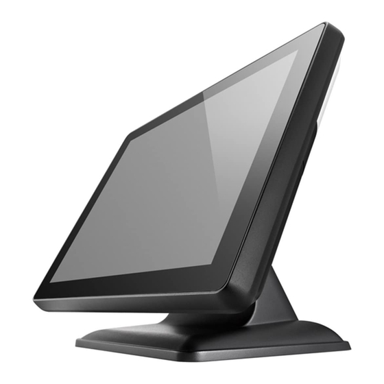
Getting to know your VariPOS/VariPPC Front view Customer display* (VFD) True flat touch panel Resistive/PCT Power LED Peripheral *(RFID/I-Button/MSR/FP) Die-casting aluminum base *all peripherals are depends on customer’s demand © Copyright Poindus Systems 2012 P9 / 54... -
Page 10: Rear View
Rear view Diverse colors I/O cover 7” 2 display* Wall mount kit for VariPPC only ARM kit for VariPPC only* *all peripherals are depends on customer’s demand © Copyright Poindus Systems 2012 P10 / 54... -
Page 11: Optional I/O Interface
Optional I/O interface 【Standard Version】 The last I/O is LPT port 【VGA Version】 The last I/O is VGA port © Copyright Poindus Systems 2012 P11 / 54... -
Page 12: Using The Touch Screen
3. At the Windows 7 Operation System environment, when customer want to use PCT touch multi-touch it is not required to install the touch driver. 4. Resistive touch is RS232 interface (COM6) and the PCT touch is USB interface. © Copyright Poindus Systems 2012 P12 / 54... - Page 13 5. Calibration with EETI touch utility: please into “tool” page and press “4 Points Calibration”. 6. Calibration in WIN7: Control panel Hardware and SoundTablet PC settingCalibrate the screen from pen or touch input © Copyright Poindus Systems 2012 P13 / 54...
- Page 14 • Spray a small amount of a household glass cleaner onto the supplied cleaning cloth and gently wipe the screen surface. • Do not spray the cleaner directly on the screen. (Resistive touch panel only) • Do not use an abrasive cleaner or a coarse cloth when cleaning the screen. © Copyright Poindus Systems 2012 P14 / 54...
-
Page 15: Specification
Audio Port 1 x Line-out ; 1 x Mic-In PS/2 Port 1 x PS/2 connector for Keyboard LPT Port 1 x DB-25 Printer Port (Standard) VGA Port 1 x DB-15 VGA Port (Optional) © Copyright Poindus Systems 2012 P15 / 54... - Page 16 100 x 100mm Operating Temperature 0ºC ~ 40ºC, 10% ~ 90% RH, non-condensing Storage Temperature -20ºC ~ 60ºC, 10% ~ 90% RH, non-condensing *Poindus reserves the right to change the specification without prior notice. © Copyright Poindus Systems 2012 P16 / 54...
-
Page 17: System Assembly & Disassembly
3. Release the screws of hinge cover 4. Remove the plastic hinge cover parts 5. Release the screws of base 6. Open the plastic cover from two sides 7. Release the screws of aluminium back frame © Copyright Poindus Systems 2012 P17 / 54... - Page 18 © Copyright Poindus Systems 2012 P18 / 54...
-
Page 19: Replace The Hdd
5. Screw 4 x round screws on the HDD tray and insert the HDD tray into the whole system HDD slot 6. Fix HDD tray on the system with the 1x screw © Copyright Poindus Systems 2012 P19 / 54... - Page 20 3SMUH30061N0 ROUND WASHER HEAD SCREWS:m3*0.5-6MM,NI Security Screws* * There are security screws and a screw driver enclosed in product carton. * Customers can use the special security screws to ensure HDD security. © Copyright Poindus Systems 2012 P20 / 54...
-
Page 21: Install The Customer Display
3. Connect the customer display into COM3 via the cable management slot and adjust COM3 voltage to +12V in BIOS (refer to Chapter 6) 4. Fasten the IO cover into the right position and turn the system on the right position. © Copyright Poindus Systems 2012 P21 / 54... -
Page 22: Configure The Com3 Pin9 For Customer Display
When the BIOS Main Menu is displayed, the following items can be selected. Use the arrow keys to select items and the enter key to accept and enter the sub-menu. Enter System Overview Advanced Settings Use this menu for set up super IO configuration. © Copyright Poindus Systems 2012 P22 / 54... - Page 23 Select Super IO Configuration Serial Port 1-4 Pin9 Mode Enter into serial port 1- 4 Pin9 Mode and set up the options. Select the serial port 1 Pin9 mode. Save and Exit © Copyright Poindus Systems 2012 P23 / 54...
-
Page 24: Install The Second Display
Install a Second Display 1. Slide the 2 display hinge into the hinge holder on VariPOS. 2. Tighten the 4 screws that attached in the accessory box. © Copyright Poindus Systems 2012 P24 / 54... - Page 25 3. Plug the VGA cable to VGA port on the terminal. 4. Don’t forget to insert the I/O cover. © Copyright Poindus Systems 2012 P25 / 54...
- Page 26 5. Done © Copyright Poindus Systems 2012 P26 / 54...
-
Page 27: How To Configure The 2 Nd Display Resolution
How to configure 2 display resolution 1. Please access control panel“Intel GMA Driver”. The Primary Device is “Notebook” and Secondary Device is “Monitor” 2. Clone mode, the resolution for both display is 800*600 © Copyright Poindus Systems 2012 P27 / 54... - Page 28 3. Extend mode, the resolution for main display is 1024*768 and 2 display is 800*600. © Copyright Poindus Systems 2012 P28 / 54...
-
Page 29: Install The External Monitor
2. Connect the extension VGA cable enclosed with the accessory box to the VGA cable of the external monitor. 3. Plug the extension VGA cable to VGA port and install the I/O cover back to finish the installation. © Copyright Poindus Systems 2012 P29 / 54... -
Page 30: Install The Cash Drawer
Size: 8bit BIT7 BIT6 BIT5 BIT4 BIT3 BIT2 BIT1 BIT0 Attribute Write Write Reserved Reserved Read Cash Drawer “CD status” Reserved Reserved Cash Drawer “CD control 2” Cash Drawer “CD control 1” © Copyright Poindus Systems 2012 P30 / 54... - Page 31 The status of cash drawer The I/O address A24h bit0 =0 (Cash Drawer is opened) The I/O address A24h bit0 =1 (Cash Drawer is close or no cash drawer connected) © Copyright Poindus Systems 2012 P31 / 54...
-
Page 32: Install The Msr & I-Button Reader
2. Connect MSR to System connector, system connector supports PS/2 and RS-232 interface. 3. Fasten the MSR screw on system MSR: RS-232 Interface System connector supports PS/2 and RS-232 interface System connector supports PS/2 and RS-232 interface © Copyright Poindus Systems 2012 P32 / 54... -
Page 33: Install The Die-Casting Aluminum Base
Install the Die-casting aluminum base Power & VFD Cable Management © Copyright Poindus Systems 2012 P33 / 54... -
Page 34: Install The Wall Mount Kits
Install the Wall Mount Kits © Copyright Poindus Systems 2012 P34 / 54... -
Page 35: Motherboard Information
Motherboard information Motherboard Layout (Sandy Bridge) © Copyright Poindus Systems 2012 P35 / 54... -
Page 36: Connectors & Jumper Settings
IVT1 Inverter Connector FAN1 CPU Fan Connector FAN2 System Fan Connector LED2 LED Connector DIO1 Digital Input / Output Connector HDMI1 HDMI Connector DisplayPort Connector Clear CMOS SATA Power Enable for SATA4 © Copyright Poindus Systems 2012 P36 / 54... - Page 37 SJ1: Clear CMOS Setup JCLR1 Description Clear CMOS Normal operation COM3 / 4 : RJ48 for COM3 / 4 Port PIN1 PIN2 PIN3 PIN4 PIN5 PIN6 PIN7 PIN8 PIN9 PIN10 © Copyright Poindus Systems 2012 P37 / 54...
-
Page 38: Spare Parts List
SPARE PARTS: TOUCH PANEL CAPACITIVE no grid W/LED XTOUCHCW002B hole (WHITE) ASS'Y,PP01 SPARE PARTS: TOUCH PANEL RESISTIVE W/LED cable XTOUCHRB001A (BLACK) ASS'Y,PP01 SPARE PARTS: TOUCH PANEL RESISTIVE W/LED cable XTOUCHRW001A (WHITE) ASS'Y,PP01 XTCONTROL01B SPARE PARTS: PCT TOUCH CONTROLER ASS'Y,PP01 © Copyright Poindus Systems 2012 P38 / 54... - Page 39 HEATSINK W/thermal pad, FOR VARI POS/PPC 815 3XMC00000080 RAM Modular HEATSINK W/thermal pad 6PN115052110 LCD PANEL: AUO , 15" TFT, 1024x768 6PN117001710 LED PANEL FOR 2 DISPLAY 61V205510400 INVERTER:DUAL LAMP 5.5mA PLCD1715204BE © Copyright Poindus Systems 2012 P39 / 54...
- Page 40 6CR000000010 MSR Module RS232 6CR000000020 MSR Module PS2 6CR842000000 I-BUTTON READER MODULE FINGERPRINT: USB FINGERPRINT READER MODULE 6PP000000031 50012-001 6PP000000021 MIFARE SECTOR READER (MF320U-PD) 6LN0WA160CUN WIRELESS 802.11 b/g/n USB WA-160CUN (ABOCOM) © Copyright Poindus Systems 2012 P40 / 54...
- Page 41 RAM: 4G DDRIII 1333MHz 204P,BRAND:HYNIX 6RMS04G48A10 (256Mx8*16) 6RMS02G48A10 RAM: 2G DDRIII 1333MHz 204P,BRAND:HYNIX (256Mx8*8) 2UCPUCELB810 INTEL CPU : Celeron B810 2UCPUI32330M INTEL CPU : i3 2330E 2UCPUI52510E INTEL CPU : i5 2510E © Copyright Poindus Systems 2012 P41 / 54...
- Page 42 XHDD32000010 HDD 320G ASSY,PP01 XSSD008IN010 INNODISK SSD 8G ASSY,PP01 XSSD016IN010 INNODISK SSD 16G ASSY,PP01 XSSD032IN010 INNODISK SSD 32G ASSY,PP01 XSSD064IN010 INNODISK SSD 64G ASSY,PP01 VFD BOARD: W/FUTABA/10P8C(COM) V1.0 52F008V10006 Cable: 3CW000000740 © Copyright Poindus Systems 2012 P42 / 54...
- Page 43 52ADB0000010 AD BOARD FOR 2 DISPLAY 6PWA1204C000 POWER ADAPTER: DC12V/10A EA11353A-120(25) 3CP000000050 POWER CORD (Brazil) TO MINI 3P 3CP000000040 POWER CORD (AU) TO MINI 3P 3CP000000030 POWER CORD (UK) TO MINI 3P © Copyright Poindus Systems 2012 P43 / 54...
- Page 44 D-SUB15PIN male, DuPont2.54, 2*5PIN+JST 2.0 4PIN,140mm, Inverter cable: JSP P=2.0 6pin female, JST P=2.0 5pin 3CW000000020 female, 100mm SATA HDD cable: SATA 7+15pin female, SATA 7pin female, 3CW000000540 JST P=2.5 4pin female, 230mm © Copyright Poindus Systems 2012 P44 / 54...
- Page 45 320mm 3CW000000050 LPT cable: DuPont P2.0 2x13pin female, DB25, 1600mm VFD cable: RJ48 10P10C TO RJ48 10P10C 3CW000000150 L=160mm(KC3951) for 52FVFDV1000D VFD cable: RJ48 10P10C TO RJ48 10P10C 3CW000000740 L=160mm for 52F008V10006 © Copyright Poindus Systems 2012 P45 / 54...
- Page 46 3 in 1 cable: for MSR, Finger printer and I-Button 3CW000000310 3 in 1cable: for MSR+RFID only Extend VGA cable:DS-UB15PIN female,D-SUB15PIN 3CW000000190 female,110mm, W/O power pin 3CMD9MJT0100 COM3 CABLE: RJ45/DB9 3P00040B0600 LCD SIDE COVER: Gray © Copyright Poindus Systems 2012 P46 / 54...
- Page 47 3P00040E0400 LCD SIDE COVER: White 3P00040B0200 LCD SIDE COVER: Black 3P00050D0200 HINGE COVER: Black 3P00050D0600 HINGE COVER: Gray 3P00050F0400 HINGE COVER: White © Copyright Poindus Systems 2012 P47 / 54...
- Page 48 3P00050D1000 HINGE COVER: Green 3P00050D0800 HINGE COVER: Red 3P00032D0800 PPC I/O cover: Red 3P00032D0600 PPC I/O cover: Gray 3P00032F0400 PPC I/O cover: White © Copyright Poindus Systems 2012 P48 / 54...
- Page 49 3P00032D1000 PPC I/O cover: Green 3P0003D0200 PPC I/O cover: Black 3P00030D0610 POS I/O cover w/o VFD: Gray 3P00030D0810 POS I/O cover w/o VFD: Red 3P00030D1010 POS I/O cover w/o VFD: Green © Copyright Poindus Systems 2012 P49 / 54...
- Page 50 3P00030F0410 POS I/O cover w/o VFD: White 3P00030D0210 POS I/O cover w/o VFD: Black 3P00031D0610 POS I/O cover W/VFD: Gray 3P00031D0810 POS I/O cover W/VFD: Red 3P00031D1010 POS I/O cover W/VFD: Green © Copyright Poindus Systems 2012 P50 / 54...
- Page 51 3P00031F0410 POS I/O cover W/VFD: White 3P00031D0210 POS I/O cover W/VFD: Black 3P00060D0600 VFD cover: Gray 3P00060D0800 VFD cover: Red 3P00060D1000 VFD cover: Green © Copyright Poindus Systems 2012 P51 / 54...
- Page 52 3P00060F0400 VFD cover: White 3P00060D0200 VFD cover: Black 3P00090D0600 display rear cover: Gray 3P00090D0800 display rear cover: Red 3P00090D1000 display rear cover: Green © Copyright Poindus Systems 2012 P52 / 54...
- Page 53 3P00090F0400 display rear cover: White 3P00090D0200 display rear cover: Black 3P00070P0910 VFD LENS 3P00110K0200 display LENS: Black 3P00110K0400 display LENS: White © Copyright Poindus Systems 2012 P53 / 54...
-
Page 54: Version Change History
Version Change History Version Change Date Change Content V1.0 October, 2011 Release V1.1 Feb, 2012 Upgrade spare parts V2.0 Dec, 2012 Structure change Add more product information V2.1 Jul, 2013 Modified support OS © Copyright Poindus Systems 2012 P54 / 54...
Need help?
Do you have a question about the VariPOS 815 and is the answer not in the manual?
Questions and answers