Table of Contents
Advertisement
Quick Links
. . . . . . . . . . . . . . . . . . . . . . . . . . . . . . . . . . . . . . . . . .
Scorpion 24 DDS-3 Tape Drive
. . . . . . . . . . . . . . . . . . . . . . . . . . . . . . . . . . . . . . . . . .
STD124000N
. . . . . . . . . . . . . . . . . . . . . . . . . . . . . . . . . . . . . . . . . .
STD224000N
. . . . . . . . . . . . . . . . . . . . . . . . . . . . . . . . . . . . . . . . . .
STD624000N
. . . . . . . . . . . . . . . . . . . . . . . . . . . . . . . . . . . . . . . . . .
Product Manual
. . . . . . . . . . . . . . . . . . . . . . . . . . . . . . . . . . . . . . . . . .
Advertisement
Table of Contents

Related Manuals for Seagate STD124000N


Summary of Contents for Seagate STD124000N
- Page 1 ......... . STD124000N .
- Page 3 ......... . STD124000N .
- Page 4 © 1997 Seagate Technology, Inc. All rights reserved Publication Number: 10004436-002, Rev. B, May, 1998 Seagate, Seagate Technology, the Seagate logo, Scorpion and the Scorpion logo are trademarks or registered trademarks of Seagate Technology, Inc. Other product names are trademarks or registered trademarks of their owners.
-
Page 5: Fcc Notice
This booklet (Stock No. 004-000-00345-4) is available from the U.S. Government Printing Office, Washington, DC 20402. Warning. Changes or modifications made to this equipment which have not been expressly approved by Seagate Technology may cause radio and television interference problems that could void the user’s authority to operate the equipment. -
Page 6: About This Manual
About This Manual All information contained in or disclosed by this document is considered proprietary by Seagate Technology. By accepting this material, the recipient agrees that this material and the information contained therein are held in confidence and in trust and will not be used, reproduced in whole or in part, nor its contents revealed to others, except to meet the purpose for which it was delivered. -
Page 7: Table Of Contents
Contents Introduction ............... 1 Overview....................1 DDS Format Standard Compatibility Scorpion 24 Capacity and Transfer Rates Features ....................3 Models ....................4 DAT Technology Overview..............6 Helical Scan Recording..............6 Recording Formats ................ 7 DDS-3 Recording Format ............7 DDS-2 Recording Format ............7 DDS Recording Format ............ - Page 8 Loading/Unloading a Cartridge (Normal Operation) ...... 37 Unloading a Cartridge (Manual Operation) ........38 Using a Blank Cartridge ..............39 Using a Cartridge Containing Data ............. 40 Loading Revised Firmware Using Seagate Firmware Cartridges..40 Flash Memory ..................40 Firmware Download Process.............. 41 SCSI Interface ..............43 Introduction ..................
- Page 9 SCSI/Data-Compression Chip ............68 Overview ..................68 Features ..................68 Theory of Operations............71 Overview.................... 71 The STD124000N Drive............... 72 Motors and Control Circuits............73 SCSI Controller................74 Helical Scan Recording—Four-Head Design ........ 75 Motors and Control Circuits ..............76 Read and Write LSI ..............
- Page 10 Contents Flash Memory ..................77 Sensors ..................... 78 Read-After-Write ................78 Media Recognition System (MRS)............79 DDS Data Cartridge ................79 Maintenance and Reliability ...........83 Maintenance ..................83 Head Cleaning ................83 Automatic Drive Spin-Down and Write ......... 84 Guidelines for High Temperature or Humidity Conditions (Outside the Specified Operating Environment)....
- Page 11 Figures Figure 1. 3.5-inch Internal DDS Drive ........... 5 Figure 2. 5.25-Inch Internal DDS Drive..........5 Figure 3. External DDS Drive ............... 6 Figure 4. Internal DDS Drive—General Dimensions ......10 Figure 5. Internal DDS Drive with Rails—General Dimensions.... 10 Figure 6.
- Page 12 Figures Page DAT Drives...
-
Page 13: Introduction
1.1 Mbytes per second, 2.2 Mbytes per second compressed. The Scorpion 24 drive combines established DAT technology, high-density recording and hardware data-compression capability along with Seagate’s proven computer grade design to provide unmatched reliability and performance characteristics among DDS products. The Scorpion 24 is ideal for workstation,... -
Page 14: Scorpion 24 Capacity And Transfer Rates
Kbytes/sec Kbytes/sec Mbytes/sec In data-compression mode, the Seagate Scorpion 24 drive typically doubles the storage capacity and transfer rate of the native uncompressed operation. Tape capacity and sustained data-transfer rate are also dependent upon the characteristics of the files being compressed, along with other system parameters, including the speed of the host, the operating system and the application software used. -
Page 15: Features
Introduction Chapter 1 Features The Scorpion 24 DDS drive represents Seagate’s commitment to engineering reliable and durable tape drive products that implement leading-edge technology. Key features of the drive include: Platform based on 3.5-inch DDS drive components 3.5-inch internal form-factor for installation in a 3.5-inch half-height space (model STD124000N) 3.5-inch drive with factory-installed 5.25-inch mounting rails and bezel for... -
Page 16: Models
SCSI controller facilitates easy integration into a variety of systems. Scorpion 24 Model Names Capacity 24.0 Gbytes* 3.5-in internal STD124000N 5.25-in internal STD224000N External STD624000N *Typical with data compression Scorpion 24 models include: A 3.5-inch, half-height DDS-3 drive that mounts internally (model... -
Page 17: Figure 1. 3.5-Inch Internal Dds Drive
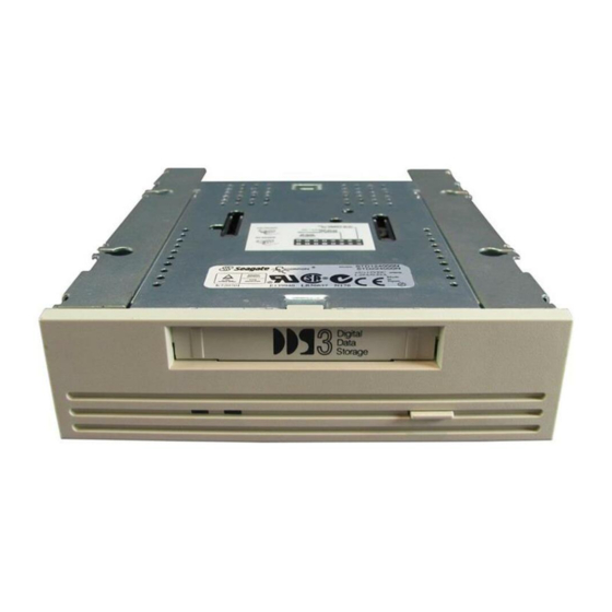
Introduction Chapter 1 Figures 1, 2 and 3 illustrate the internal, internal with rails and external drives, respectively. Figure 1. 3.5-Inch Internal DDS Drive Figure 2. 5.25-Inch Internal DDS Drive Product Manual Page 5... -
Page 18: Dat Technology Overview
Chapter 1 Introduction Figure 3. External DDS Drive DAT Technology Overview Developed for the audio electronics market, DAT technology was first applied in computer peripherals in the late 1980s. Unlike traditional magnetic tape audio cartridge products, DAT technology proves inherently reliable through the helical scan recording method, which provides a high recording density with a very low error rate. -
Page 19: Recording Formats
Recording Formats The Seagate Scorpion 24 DDS drive is designed to comply with the industry- standard DDS-3, DDS-2, DDS-DC and DDS recording formats. These formats are summarized in the following text. -
Page 20: Dds-Dc Recording Format
Chapter 1 Introduction DDS-DC Recording Format A superset of the basic DDS format, DDS-DC drives can write compressed and uncompressed data to the same cartridge. Because DDS-DC is based on the DDS format, backward-compatibility is maintained. Introduced by the DDS Manufacturers Group and approved by ANSI and ECMA, DDS-DC is a record compression industry-standard format that provides support for lossless compression algorithms based on substitution—such as those of the Lempel-Ziv family. -
Page 21: Specifications
Specifications Overview This chapter includes technical specifications for the internal and external SCSI drives. This information covers the following specifications and requirements: Physical specifications Power requirements Drive performance specifications Environmental requirements DAT cartridge specifications Regulatory compliance Physical Specifications The physical specifications of the Scorpion 24 internal and external models are listed in the following table: Specification Internal... -
Page 22: Figure 4. Internal Dds Drive-General Dimensions
Chapter 2 Specifications 101.6 41.3 104.1 Cassette in Place (Green) 41.2 Drive Busy (Yellow) Figure 4. Internal DDS Drive—General Dimensions 41.4 174.6 Cassette 149.1 in Place (Green) 41.2 Drive Busy (Yellow) Figure 5. Internal DDS Drive with Rails—General Dimensions Page 10 DAT Drives... -
Page 23: Power Specifications
Specifications Chapter 2 Drive Busy (Yellow) Cassette in Place (Green) Power On (Green) Figure 6. External Subsystem—General Dimensions Power Specifications The following table lists the power specifications for the internal Scorpion 24 drives. DC Voltage +12 VDC +5 VDC Voltage Tolerance + or –... -
Page 24: Drive Performance Specifications
Chapter 2 Specifications The external drives have a built-in power supply that senses the incoming voltage and automatically adapts to voltages within the range of 100 to 240 volts, 50 to 60 Hz. The following table lists its power specifications. Specification AC Input Voltage 100 (Japan) -
Page 25: Environmental Requirements
2. Mechanism DDS Cartridge Specifications DDS drives provide maximum data integrity and reliability when Seagate-qualified DDS cartridges are used as the recording media. Seagate maintains an ongoing program to qualify manufacturers of DDS cartridges. The following cartridges are recommended: DDS data cartridge: model M31300, 60-meter tape... -
Page 26: Regulatory Compliance
Chapter 2 Specifications Regulatory Compliance These DDS drives comply with the regulations listed in the following table. Agency Regulation C22.2, No. 950-M89 TUV-RHEINLAND EN 60 950 1950 Class A and Class B CE compliance 1. Required compliance for external model; verification on file for internal models. Use these drives only in equipment where the combination has been determined to be suitable by an appropriate certification organization (for example, Underwriters Laboratories Inc. -
Page 27: Installation
Installation Introduction This chapter explains how to install the Scorpion 24 drive. Some of the information relates to all models; other information is specifically aimed at either the internal or external models. The following paragraphs briefly outline the organization of this chapter. -
Page 28: Unpacking And Inspection
Place shipping containers on a flat, clean, stable surface; then carefully remove and verify the contents against the packing list. If parts are missing or the equipment is damaged, notify your Seagate representative. Always save the containers and packing materials for any future reshipment. - Page 29 Installation Chapter 3 All signals except GROUND and TEMPWR must be terminated at both ends of the cable. Each signal termination consists of 220 ohms (± 5%) to TEMPWR and 330 ohms (± 5%) to GROUND and must meet the following specifications or requirements: Terminators must supply a characteristic impedance of 100 to 132 ohms.
-
Page 30: Scsi Connector-Internal Models
Chapter 3 Installation SCSI Connector—Internal Models The internal drive provides a 50-pin, right-angle, dual-row connector on the main PCB at the rear of the drive. The pin assignments for this single-ended connector are listed in the following table. Note. All odd pins, except pin 25, are connected to signal ground at the drive. Pin 25 is left open. -
Page 31: Scsi Connector-External Models
Installation Chapter 3 SCSI Connector—External Models The external drive provides two 50-pin, shielded connectors (ANSI Alternative 2) on the rear panel of the drive. These connectors consist of two rows of ribbon contacts spaced 2.16 mm (0.085 in) apart. These two connectors facilitate adding the drive to a daisy-chain configuration. Either connector is a SCSI IN connection;... -
Page 32: Installing Internal Drives
Chapter 3 Installation Installing Internal Drives The two internal models are a 3.5-inch drive that mounts internal to the computer in a 3.5-inch, half-height space and a 3.5-inch drive with mounting rails and bezel for internal installation in a 5.25-inch, half-height space. Installing these two models consists of a few easy steps: Configure the switchbank parameters and set the jumpers. -
Page 33: Figure 8. Switchbank Access-5.25-Inch Internal Model
The Scorpion 24 switchbank allows you to configure the SCSI device address, media-recognition system (MRS) mode, parity check, DDS pass-through mode (data-compression mode), Seagate’s selectable inquiry string and power-on self-test (POST). Following are brief descriptions of the various positions and with their default values. -
Page 34: Scsi Device Address (S1, S2, S3)
Archive DDS-DC Disable Enable Seagate Enable Figure 9. Dip Switch Default Settings If you need to change any of the factory-default settings, you must first power-cycle the drive by turning it off and then on again, or a SCSI Bus Reset command must be received for the new switch settings to take effect. -
Page 35: Parity Check Enable/Disable (S5)
Inquiry String (S7) The S7 switch is used to select the SCSI inquiry string. The default setting (S7=ON) enables the Seagate inquiry string. You can set it to Archive to provide compatibility with older backup software. S7 = ON enables Seagate inquiry string... -
Page 36: Setting The Jumpers
Chapter 3 Installation Setting the Jumpers The jumper block on the Scorpion 24 provides additional access to settings for SCSI ID, hardware data compression (HDC), enabling of the active terminator and termination power. For the SCSI ID jumper block settings to take effect, switches S1, S2 and S3 on the switchbank must be in the OFF position. -
Page 37: Scsi Device Address Jumpers
Installation Chapter 3 Figure 12 shows the jumper configurations for the various SCSI device addresses (IDs) and for the other options. Jumper ON Jumper OFF SCSI ID SCSI Pins Pins Pins 5, 6 3, 4 1, 2 HDC Disabled (Jumper on pins 9 and 10) Active Terminator Enabled (Jumper on pins 11 and 12) Not Connected (NC) -
Page 38: Hardware Data Compression
The terminator power fuse is located beside the terminator power jumper. In the event that the fuse has blown to prevent damage to the drive, please return the drive to the nearest Seagate authorized repair facility for replacement. Page 26 DAT Drives... -
Page 39: Mounting The Drive
Installation Chapter 3 Mounting the Drive You can install the internal drives in three different orientations: one horizontal (eject button right) and two vertical (eject button up or eject button down). The internal drive chassis contains threaded mounting holes for M3.0 metric screws. The maximum length for the M3.0 metric screws is 4 mm. -
Page 40: Figure 14. Mounting Hole Locations (Internal Drive With Rails)
Chapter 3 Installation The chassis for the internal drive with rails contains threaded mounting holes for M3.0 metric screws. The maximum length for the M3.0 screws is 4 mm. Four are located on the bottom and six are on each side of the frame. See Figure 14. 9.9 mm 41.3 mm (0.39 in) -
Page 41: Completing The Power And Interface Connections
Installation Chapter 3 Completing the Power and Interface Connections The power and interface connectors for the internal models are located at the back of the drive unit. Figure 10 illustrates these connections for the 3.5-inch internal drive. Figure 11 illustrates these connections for the 5.25-inch internal drive with rails. Note. -
Page 42: Selecting The Scsi Address
When the drive is either the only drive in the chain or the last drive in the chain, a single interface cable is attached to one connector, and a terminating plug is installed in the other connector. (Seagate part number 38-9-74000000) When the drive is within the chain, the interface cable from the preceding device is connected in one connector, and an interface cable is also connected from the other connector to the following device. -
Page 43: Connecting The Power Cord
Installation Chapter 3 Figure 16 illustrates these daisy-chain connections DAT DRIVE AS THE FINAL DEVICE DAT DRIVE TERMINATOR DAT DRIVE WITHIN A CHAIN FINAL DAT DRIVE DEVICE MUST HAVE TERMINATOR Figure 16. Daisy Chain Diagram The same type of mating connector is used for either of the daisy-chain connections. - Page 44 Chapter 3 Installation Page 32 DAT Drives...
-
Page 45: Drive Operations
Loading and unloading a cartridge Using a blank cartridge Using a cartridge that contains data Loading revised firmware through Seagate firmware cartridges Data Compression Operation Default operation for the Scorpion 24 drive is to have data compression enabled— the drive automatically compresses all data written to tape and decompresses all compressed data read from tape. -
Page 46: Front Panel Led Operation
When flashing rapidly, the drive could not write the tape correctly (maximum rewrite count exceeded). The WRITE operation failed. First, clean the drive heads using an approved cleaning cartridge, such as the Seagate Model M7301. If the LED continues flashing, use a new cartridge for future writes. Page 34... -
Page 47: Figure 17. Front Panel-Internal Model
Drive Operations Chapter 4 Audio Mode Indicator The cartridge status LED flashing in conjunction with the drive status LED indicates that a prerecorded audio cartridge is inserted and is playing automatically. External Power LED The round, green LED on the external drive illuminates when power is applied to the drive. -
Page 48: Figure 18. Front Panel-Internal Model With Rails
Chapter 4 Drive Operations Cassette Insertion Slot Cassette in Place (Green) Eject Button Drive Busy (Yellow) Figure 18. Front Panel—Internal Model with Rails Cassette Drive Busy Insertion Slot (Yellow) Cassette Insertion Slot Cassette in Place (Green) Eject Button Power On (Green) Figure 19. -
Page 49: Loading/Unloading The Cartridge
Drive Operations Chapter 4 Loading/Unloading the Cartridge The cartridge insertion slot on the front panel of the Scorpion 24 drive provides easy access to the drive. This section explains loading and unloading a cartridge under normal operating conditions. It also explains the manual procedure for removing a cartridge abnormally lodged in the drive. -
Page 50: Unloading A Cartridge (Manual Operation)
Chapter 4 Drive Operations Unloading a Cartridge (Manual Operation) If a power outage occurs while a cartridge is loaded or the automatic unload procedure previously explained fails, you may want to manually unload a cartridge from the drive. The following steps outline the manual cartridge unloading and removal procedure. -
Page 51: Using A Blank Cartridge
Drive Operations Chapter 4 Turn the unit upside down and remove the four screws (two screws on each side) that attach the external cover to the chassis unit. Remove the exterior cover and retain the screws. On the drive unit inside the chassis, remove the top cover by removing the two screws at the top edge near the rear of the unit (one on each side). -
Page 52: Using A Cartridge Containing Data
SCSI firmware needs to be upgraded. With the permanently installed, electrically upgradeable flash memory, revised SCSI firmware for the drive can be loaded using any one of three methods: 1) Seagate OEM firmware cartridges (see Chapter 4); 2) through the host SCSI bus; and 3) through the drive serial port (see Chapter 8). -
Page 53: Firmware Download Process
Note. At this time, we recommend that you power cycle the drive to refresh any new parameter information and to execute the power-on self-test (POST) to ensure proper unit functionality. Firmware upgrade cartridges are available only to qualified Seagate OEM customers. Contact your Seagate sales representative for information. Product Manual... - Page 54 Chapter 4 Drive Operations Page 42 DAT Drives...
-
Page 55: Scsi Interface
This chapter summarizes the SCSI-2 message codes, status codes and commands. Refer to chapter 3 for specific SCSI cabling and connection information. Refer to Seagate’s DAT Tape Drive and Autoloader SCSI Manual (part number 10002663-00 x ) for detailed developer information relative to SCSI implementation. - Page 56 Chapter 5 SCSI Interface SCSI Status Codes 4-bit Status Code Bits Definition Good Status Check Condition Busy Intermediate Status Reservation Conflict SCSI Commands Code Type Command Test Unit Ready Rewind Request Block Address Request Sense Read Block Limits Read Write Seek Block Write Filemarks Space...
-
Page 57: Ansi X3.131, 199X Conformance Statement (Scsi-2)
SCSI Interface Chapter 5 ANSI X3.131, 199x Conformance Statement (SCSI-2) General Features Disconnect/reconnect, arbitration (required in SCSI-2) Single-ended drivers Termination power supplied to cable (jumper option) Supports both single and multi-initiator systems Fixed and variable block transfer lengths Hard reset Synchronous data transfers Parity implemented (switch option) Space blocks, filemarks and EOD... -
Page 58: Typical System Configurations
Chapter 5 SCSI Interface Typical System Configurations The SCSI standard provides support for up to eight SCSI addresses or IDs. These IDs refer to host adapters or peripheral devices such as printers, magnetic discs or tape drives. Any combination of a single host and up to seven additional SCSI devices can be chained together on a single SCSI cable. -
Page 59: Dds-3 Tape Format
DDS-3 Tape Format Introduction to DDS Recording Format Standards One of the major benefits in DDS technology is in the consistency and strength of the format standards. Precise recording format standards provide the basis for well-defined interchange requirements. DDS format standards define physical cartridge case requirements, physical and electrical requirements for the unrecorded tape, format requirements for tape interchange, measurement methods, and test-environment definition and provide measurable conformance requirements. -
Page 60: Basic Groups
Chapter 6 Tape Formats Entities are defined as logical objects that contain processed records. Entities, unprocessed records and separator marks are collected into groups . Groups are processed through a series of transformations including randomizing, interleaving, blocking, generating and inclusion of ECC, and translation of data bytes to channel bits before recording to tape. -
Page 61: Entities
Tape Formats Chapter 6 Entities Each entity includes an entity header and a processed record sequence. The header is 8 bytes long and precedes the processed record sequence. By definition, all processed records contained within an entity go through the same processing algorithm;... -
Page 62: Dds-3 Track Geometry
Chapter 6 Tape Formats DDS-3 Track Geometry The Scorpion 24 DDS-3 drive records to tape in a helical track pattern. This track pattern is dependent upon the relationship of two items: 1) the direction of tape motion and 2) the rotational axis of a pair of record heads located on the tape drive cylinder. -
Page 63: Recorded Patterns
Tape Formats Chapter 6 DDS-3 Track Specifications Parameter Specification 9.053 µm ± 0.045 µm Average Track Pitch Variations of Track Pitch 2% maximum Track Width 9.053 µm Nominal 9.1 µm ± 1.8 µm Measured Track Angle 6° 22' 39.6" 23.521 mm ± 0.047 mm Track Length Ideal Centerline 1.900 mm from the... -
Page 64: Positioning Accuracy
Chapter 6 Tape Formats Positioning Accuracy The DDS-3 specification reflects a tighter requirement for positioning accuracy when compared to previous standards. The DDS-3 standard specifies the position reference point of all tracks to be 1.906 mm from the tape reference edge. The position reference point of any adjacent 12 tracks, or positional reference point variance, must be within 1.0 µm of the mean position reference point of all tracks within the described continuum. -
Page 65: Tape Layouts In The Dds-3 Standard
Tape Formats Chapter 6 Read Head Subcode Active track Case 1: The head is off track because the tape is moving too fast. Too much time elapses before the heads read the subcode. To bring the heads on track, the drive automatically slows the tape. Case 2: The head is on track, and no corrective action is necessary. -
Page 66: Device Area
Chapter 6 Tape Formats Pos. Tol. Recorded Recorded Pos. Tol. Vendor System System System Vendor Device Reference Band Group Data Group Data Group Band Preamble Postamble Group Area Area No. 2 No. 1 No. 2 No. 1 Preamble Device Reference System Data PBOT... -
Page 67: System Area
Tape Formats Chapter 6 System Area The System Area consists of the system preamble , the system log , the system postamble, position tolerance band 2 and the vendor group preamble . Data Area The data area consists of the vendor group and one or multiple recorded data groups . -
Page 68: Figure 28. Tolerance On Seamless Appending
Chapter 6 Tape Formats The following rules are for the DDS-3 format for a seamless append: 1. There should be one frame between Frame A and Frame B. For example, if frame A has an absolute frame number (AFN) of n , then Frame B should have an AFN of n + 2 . -
Page 69: Eod Area
Tape Formats Chapter 6 3. Amble frames between Frame A and Frame B should have a value of group number that is equal to that of Frame A. Other frames between Frame A and Frame B should have a value of group number that is greater than that of Frame A. -
Page 70: Layout Of A Partitioned Tape
Chapter 6 Tape Formats Layout of a Partitioned Tape A partitioned tape provides the end-user with two independent partitions, or effectively two single data space tapes on one tape cartridge. Each of the two partitions have the similar structure and properties to those of a single data space tape. -
Page 71: Partition 1
Tape Formats Chapter 6 Partition 1 The total number of frames in Partition 1 is recorded in the system log of Partition 1. The virtual end of tape (VEOT) is a reference point for Partition 1, the same as the PEOT on a single data space tape. -
Page 72: Housekeeping Frames
Chapter 6 Tape Formats An Empty Partition 0 consists of: A reference area A system area A data area, comprising a vendor group and at least 35 amble frames An EOD area 450 frames in length at a minimum. The vendor group preamble, the data area and the EOD area all form a continuum. No unrecorded space, physical discontinuity, seam, absolute frame number discontinuity or absolute frame number repetition is permitted. -
Page 73: Data Compression
Data Compression Introduction Data Compression—General Typical data streams of text, graphics, software code or other forms of data contain repeated information of some sort, whether it is at the text level where you can readily recognize regular repetitions of a single word or at the binary level where the repetitions are in bits or bytes. -
Page 74: Data Compression Considerations
Additionally, the data compression method must adapt to different data types, automatically providing optimum handling for all types of data. Considering these factors, Seagate engineers concluded: The most effective data compression method must compress as much data as possible under the following conditions: The transfer rate of the host computer is not impeded. -
Page 75: Hardware Compression
SCSI/data compression chip onboard the drive, with the compression processing activity transparent to the host computer and the user. Seagate’s SCSI/data compression chip is designed to provide a complete data compression system using the DCLZ algorithm. This chip provides support circuitry as well as the core DCLZ compression machine. -
Page 76: Dclz Algorithm
Chapter 7 Data Compression DCLZ Algorithm DCLZ Algorithm Within the computer industry, algorithms developed by Abraham Lempel and Jacob Ziv (enhanced later by Terry Welch) are popular, versatile and powerful compression methods. These LZ algorithms are basically of two types—LZ1, a sliding window method, and LZ2/LZW, a hashed directory method. -
Page 77: Dictionary
Data Compression Chapter 7 The following table illustrates this simplified operation. Input Build Output Code Current Match Byte String Entry Value — — — — — — — — — — — — — — — — (IN) — — —... -
Page 78: Simplified Decompression Operation
Chapter 7 Data Compression Dictionary codes, codewords 264 through 4,095: The dictionary codes refer to dictionary entries and represent multiple bytes (a string of characters) in the input data stream. These codes are built as the input stream is processed. These codes are pointers to other locations and eventually end by pointing to one of the byte values 0 through 255. - Page 79 Data Compression Chapter 7 The following steps describe a simplified version of the operation of the algorithm for decompressing data. 1. From a reset dictionary point, (which contains only control codes and encoded bytes) codewords are fetched from the input stream and looked up in the dictionary.
-
Page 80: Scsi/Data-Compression Chip
However, that interface performs byte operations in the event of an odd block size. The Seagate SCSI/data-compression chip used in the Scorpion 24 tape drive provides the basis for an effective data-compression system using the DCLZ algorithm. The chip includes a SCSI controller and a data-compression processor arranged in an inline configuration. -
Page 81: Figure 30. Layout Of Scsi/Data Compression Device
Data Compression Chapter 7 Figure 30 illustrates the layout of the SCSI/data-compression device. 100-Pin PQFP Chip Data-Compression Core Compressor Micro- Processor and SCSI Formatter Core DMA Interface SCSI Host Decom- Interface pressor 8K × 32 External Static RAM Figure 30. Layout of SCSI/Data Compression Device Product Manual Page 69... - Page 82 Chapter 7 Data Compression Page 70 DAT Drives...
-
Page 83: Theory Of Operations
Theory of Operations Overview The Scorpion 24 tape drive design integrates DAT technology (helical scan recording method) into a true computer-grade data-storage peripheral with industry- standard data-compression capability. These drives are the result of: Combining the economies of scale from the audio electronics market for key components, such as the cylinder, heads and audio LSIs, with a computer grade drive (3.5-inch) using four direct drive motors, a no-mode change mechanism and electronic tape path control for the demanding computer... -
Page 84: The Std124000N Drive
Chapter 8 Theory of Operations The STD124000N Drive The Scorpion 24 uses the helical scan recording method with a four-head cylinder design. Four direct-drive motors and one brush-type motor are used in the drive. The read and write functions use LSIs. Engineering decisions—such as the modular partitioning of the electronics and use of surface mount, low power commercial and custom LSIs—allow the drives to conform to the industry-accepted 3.5-inch form-... -
Page 85: Motors And Control Circuits
Theory of Operations Chapter 8 Motors and Control Circuits Recording Heads PRML Channel Power Read Converter DC/DC Converter Write PONTO2 (5V to 3.3 V) PRML Analog PRML Digital Flying Rotary CGA, DIFF, DRAM Veterbi ++ Read Transformer Preamp GAIN 1 Meg × 16 XLAT (16 MBit) SRAM... -
Page 86: Scsi Controller
Chapter 8 Theory of Operations SCSI Controller To Drive To Drive Electronics Electronics LED 1 ADBCLK LED 2 LED 3 DADAT LED 4 Control DDS LSI TXCLK Address ADDAT SPAW – N SPSTB – N FLASH DRAM EEPROM 128K x 16 1 Mbyte 512 BYTES PROM... -
Page 87: Helical Scan Recording-Four-Head Design
Theory of Operations Chapter 8 Helical Scan Recording—Four-Head Design In helical scan recording, the heads are positioned opposite one another on a cylinder, which is tilted approximately 6 degrees from the vertical plane and rotates counterclockwise at 4,000 revolutions per minute (rpm). At the same time, the tape moves slowly (0.430 inches per second in DDS-3 mode) in a horizontal path around part of the cylinder. -
Page 88: Motors And Control Circuits
Chapter 8 Theory of Operations The recorded tracks are written diagonally across the tape from bottom to top by each write head. Because the head is wider than the track written, tracks overlap with no tape space between them. In conventional recording, such overlap or even proximity results in crosstalk (signals from adjacent tracks interfering with signals from another track). -
Page 89: Read And Write Lsi
Issuing a SCSI Write Data Buffer command to download the firmware to the EEPROM Through the drive serial port Refer to Chapter 4 on page 33 for information about loading new firmware using a Seagate firmware upgrade cartridge. Product Manual Page 77... -
Page 90: Sensors
Chapter 8 Theory of Operations Sensors A number of mechanical and optical sensors are integrated in the drive design. The cartridge in and cartridge loading sensors are mechanical sensors that determine the position of the loading mechanism. The other mechanical sensors report specific information based on detecting the open or closed state of four recognition holes in the DAT cartridge. -
Page 91: Media Recognition System (Mrs)
LED flashes during operation. Chapter 9 discusses the DDS head-cleaning cartridge in detail. You can order both DDS data and head-cleaning cartridges from Seagate. They are packaged in multiples of five. These small (approximately 2 inches × 3 inches × 0.4 inch) cartridges house magnetic tape that is 3.81 mm (0.150 inch) wide. -
Page 92: Figure 35. Dds Cartridge
Chapter 8 Theory of Operations Figure 35. DDS Cartridge Qualified DDS cartridges are designed with specific file protect, lid and other features for information interchange and are tested to comply with the ANSI DDS specifications. The Scorpion 24 drive also recognizes all MRS cartridges when MRS is enabled. MRS cartridges have a series of alternate opaque and clear stripes at the beginning of the tape. -
Page 93: Figure 36. Cartridge Design Features
Theory of Operations Chapter 8 File Protect Hole (Restorable) Recognition Holes (1, 2, 3, 4) Datum Holes Slider Lock (1) Slider Lock (2) Lid Lock (Locked by Slider) Figure 36. Cartridge Design Features The cartridge also provides for write protection so that existing data on the cartridge is not overwritten. - Page 94 Chapter 8 Theory of Operations Page 82 DAT Drives...
-
Page 95: Maintenance And Reliability
LED in conjunction with the yellow LED indicates the presence of a prerecorded audio tape.) For a description of LED operation, see Chapter 4. To clean the drive heads, use only a Seagate-qualified DDS cleaning cartridge designed for DDS drives. Seagate offers a cleaning cartridge, Model M91301, that you can order. -
Page 96: Automatic Drive Spin-Down And Write
Chapter 9 Maintenance and Reliability Automatic Drive Spin-Down and Write To maximize tape and drive mechanism life, the drive automatically stops the cylinder when no tape read or write activity occurs. If a read or write operation occurs, normal operation resumes with no affect on the host operation. -
Page 97: Reliability
The MTTR for DAT products is less than 0.5 hour (30 minutes). The Seagate DDS drives are field-replaceable units. If a problem occurs with a subassembly or component in the drive, you should replace the entire unit. Return the drive to the factory in its original packaging. - Page 98 Chapter 9 Maintenance and Reliability Page 86 DAT Drives...
-
Page 99: Acronyms And Measurements
Acronyms and Measurements Acronyms and Abbreviations Acronym Meaning 4 direct drive ANSI American National Standards Institute automatic track finding block access table BIOS basic input output system beginning of media beginning of tape bits per inch compact disc CMOS complementary metal-oxide semiconductor Canadian Standard Association digital audio tape DCLZ... - Page 100 Appendix A Acronyms and Measurements Acronym Meaning original equipment manufacturer printed circuit board PQFP plastic quad flat pack quad flat pack quarter-inch cartridge drive standards, incorporated random access memory read-after-write SCSI small computer system interface transistor-transistor logic Underwriters’ Laboratories, Inc. volts alternating current video cassette recorder volts direct current...
-
Page 101: Measurements
Acronyms and Measurements Appendix A Measurements Measure Meaning Celsius or Centigrade centimeter decibels, A-weighted sound power reference one picowatt Fahrenheit foot or feet acceleration of a free-falling body; equal to 32.17 feet per second Gbyte gigabyte Hertz inch kilo Kbyte kilobyte kilogram kilohertz... -
Page 102: A Acronyms And Measurements
Appendix A Acronyms and Measurements Page 90 DAT Drives... -
Page 103: Vendor-Unique Scsi Information
Vendor-Unique SCSI Information Overview The DAT drives provide a configuration flash memory that contains configuration settings, the drive serial number and other data. You can reprogram some of the configuration parameters in the flash memory using the SCSI MODE SELECT command—MODE SELECT Flash Memory Configuration Page (30 ). -
Page 104: Mode Select Flash Memory Configuration Page
Appendix B Vendor-Unique SCSI Information MODE SELECT Flash Memory Configuration Page (30 You use the MODE SELECT Flash Memory Configuration page to program the configuration of the drive. The new settings do not take effect until a power-on or a SCSI reset condition occurs. -
Page 105: Mode Sense Flash Memory Configuration Page
Vendor-Unique SCSI Information Appendix B MODE SENSE Flash Memory Configuration Page (30 You use the MODE SENSE Flash Memory Configuration page to determine the user information currently configured for the drive. A drive with HW=1 (that is, that uses DIP switch settings) does not use most of the settings shown unless reprogrammed to the “use flash memory”... -
Page 106: B Vendor-Unique Scsi Information
Appendix B Vendor-Unique SCSI Information Page 94 DAT Drives... -
Page 107: Glossary
Glossary absolute frame number (AFN). A sequence number encoded in the frame. access point. Beginning of a sequence of compressed records at which point codewords to a decompression algorithm must start—whether or not the required data is at the beginning of the sequence. algorithm. - Page 108 Glossary cutout. The cut-away or step-down portion of the autoloader case that provides access to switches, jumpers and connectors. data area. The third section of a tape on a DAT cartridge, which is written as a series of groups beginning with the special vendor group. data compression.
- Page 109 Glossary frame. Two adjacent tracks, one A channel (positive azimuth) and one B channel (negative azimuth). full-height. Usually refers to a tape drive that fits into a vertical space of 3.5 inches. group. A fixed-capacity set of frames written to or read from the tape. For the DDS and DDS-DC formats, 22 frames comprise a group.
- Page 110 Glossary processed record. A sequence of codewords that results from the application of processing to an unprocessed record. processed record sequence. A sequence of one or more processed records that starts on an 8-bit boundary and ends on a subsequent 8-bit boundary. randomizing.
- Page 112 Seagate Technology, Inc. 920 Disc Drive, Scotts Valley, California 95066, USA Publication Number: 10004436-002, Rev. B, Printed in USA...
Need help?
Do you have a question about the STD124000N and is the answer not in the manual?
Questions and answers