Table of Contents
Advertisement
. . . . . . . . . . . . . . . . . . . . . . . . . . . . . . . . . . . . . . .
. . . .
DAT 72 and DDS-4 Tape Drives
. . . . . . . . . . . . . . . . . . . . . . . . . . . . . . . . . . . . . . .
. . . .
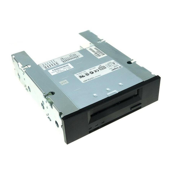
CD72LWH
. . . . . . . . . . . . . . . . . . . . . . . . . . . . . . . . . . . . . . .
. . . .
CD72LWE
. . . . . . . . . . . . . . . . . . . . . . . . . . . . . . . . . . . . . . .
. . . .
STD1401LW
. . . . . . . . . . . . . . . . . . . . . . . . . . . . . . . . . . . . . . .
. . . .
STD2401LW
. . . . . . . . . . . . . . . . . . . . . . . . . . . . . . . . . . . . . . .
. . . .
STD6401LW
. . . . . . . . . . . . . . . . . . . . . . . . . . . . . . . . . . . . . . .
. . . .
Product Manual
. . . . . . . . . . . . . . . . . . . . . . . . . . . . . . . . . . . . . . .
Advertisement
Table of Contents


Need help?
Do you have a question about the CD72LWH and is the answer not in the manual?
Questions and answers