Delta AH500 series Hardware Manual
Programmable logic controllers
Hide thumbs
Also See for AH500 series:
- Manual (780 pages) ,
- Programming manual (749 pages) ,
- Hardware operation manual (681 pages)
Table of Contents
Advertisement
Quick Links
Advertisement
Chapters
Table of Contents
Troubleshooting

Related Manuals for Delta AH500 series


Summary of Contents for Delta AH500 series
- Page 2 Chapter 1 Product Introduction Table of Contents Overview ....................1-2 1.1.1 Related Manuals ................1-2 1.1.2 Model Description................1-2 Characteristics...................1-7 1 - 1...
-
Page 3: Overview
This manual introduces the electrical specifications for the AH500 series programmable logic controllers, the appearances, the dimensions, and etc. 1.1.1 Related Manuals The related manuals of the AH500 series programmable logic controllers are composed of the following. AH500 Quick Start It guides users to use the system before they read the related manuals. - Page 4 Ch ap te r 1 Prod uc t In tr od uc tion Classification Model Name Description It is a basic CPU module with one built-in Ethernet port, one built-in RS-485 port, one built-in USB port, and one built-in AHCPU520-EN SD interface.
- Page 5 AH5 00 Hardw are Manu al Classification Model Name Description 12~24 V DC 0.1 A AH32AN02P-5B 32 outputs Sinking output DB37 connector 12~24 V DC 0.1 A AH32AN02T-5B 32 outputs Sourcing output DB37 connector 12~24 V DC 0.1 A AH64AN02T-5C 64 outputs Sinking output Latch connector...
- Page 6 AH05PM-5A Two-axis pulse train motion control module (1 MHz) module Six-axis pulse train motion control module AH10PM-5A (Four axes: 1 MHz; Two axes: 200 kHz) Twelve-axis DMCNET (Delta Motion Control Network) AH20MC-5A motion control module (10 Mbps) 1 - 5...
- Page 7 AH5 00 Hardw are Manu al Classification Model Name Description It is an Ethernet master module with two built-in Ethernet AH10EN-5A ports, and supports a Modbus TCP master. It is a serial communication module with two RS-485/RS-422 ports, and supports Modbus and the UD link protocol.
-
Page 8: Characteristics
(2) Supporting more inputs and outputs The AH500 series CPU module supports up to 4,352 local digital I/O or 512 analog I/O. A complete AH500 system consists of eight backplanes at most, including a main backplane. - Page 9 AHRTU-DNET-5A (4) Larger program capacity and memory The program capacity of the AH500 series CPU modules can be up to 256 ksteps. Users do not need to use a more advanced CPU if the program capacity becomes large. The AH500 series CPU module has 64 kwords of memory. Besides, users can declare up to 1024 function blocks.
- Page 10 (6) Strong function block Not only the standard IEC61131-3 function blocks are supported, but also the convenient function blocks provided by Delta Electronics, Inc. are supported. Users can write the program frequently executed in a function block so that the program becomes more structured and can be executed more conveniently.
- Page 11 Besides, users do not need to buy a communication cable for the CPU module. They can use a general USB cable to connect to the AH500 series CPU module.
- Page 12 Log storage: The system error log and the system status log (12) Hot swap The AH500 series I/O modules support the on-line uninterruptible hot swap. When the system runs, users can replace the module which breaks down without disconnecting the module.
- Page 13 AH5 00 Hardw are Manu al Step 1: Setting the PLC to RUN Step 2: Entering the on-line mode 1 - 1 2...
- Page 14 Ch ap te r 1 Prod uc t In tr od uc tion Step 3: Entering the debugging mode (14) Supporting the on-line editing mode When the system runs, users can make use of the on-line editing mode to update the program without affecting the operation of the system.
- Page 15 AH5 00 Hardw are Manu al After the program is modified and compiled, users can update the program in the CPU module by clicking 1 - 1 4...
-
Page 16: Table Of Contents
Chapter 2 Installing the Hardware Table of Contents AH500 Hardware Framework ..............2-2 2.1.1 Component Parts of the AH500 Hardware .........2-2 2.1.1.1 Necessary Components ..............2-2 2.1.1.2 Accessories.................2-4 2.1.2 Installing Modules on a Main Backplane ..........2-7 2.1.3 Installing Modules on an Extension backplane........2-8 2.1.4 Connecting a Main Backplane to an Extension Backplane ....2-8 Warning .....................2-9... -
Page 17: Ah500 Hardware Framework
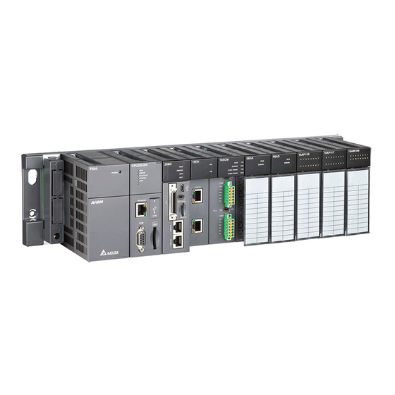
AH5 00 Hardw are Manu al 2.1 AH500 Hardware Framework 2.1.1 Component Parts of the AH500 Hardware A complete AH500 system consists of a main backplane, extension backplanes, power supply modules, a CPU module, I/O modules, and extension cables. The basic AH500 system is illustrated below. - Page 18 Please refer to the following table for information about the communication interfaces and the main applications. The specifications for the interface on an extension backplane are defined by Delta Electronics, Inc. itself. The interface is used to connect the backplanes, and users need to use a Delta extension cable.
-
Page 19: Accessories
Computer communication Industrial control network DeviceNet DeviceNet The maximum data transmission rate is 1 Mbps. Interface on an Delta extension Extension cable for a complete AH500 system connector backplane 2.1.1.2 Accessories The following are the accessories for an AH500 system. Users can select them according to their needs. - Page 20 C h ap te r 2 I ns ta ll in g t he H a r dw a r e 12~24 V DC 0.5 A 16 outputs AH16AN01P-5A Sourcing output Terminal block 110/220 V AC 0.5 A 16 outputs AH16AN01S-5A TRIAC Terminal block...
- Page 21 AH5 00 Hardw are Manu al 24 V DC 5 mA 8 inputs 12~24 V DC AH16AP11P-5A 0.5 A 8 outputs Sinking output Terminal block The analog input/output modules: Four-channel analog input module 16-bit resolution AH04AD-5A 0~10 V, 0/1~5 V, -5~+5 V, -10~+10 V, 0/4~20 mA, and -20~+20 mA Eight-channel analog input module 16-bit resolution AH08AD-5B...
-
Page 22: Installing Modules On A Main Backplane
CPU module, and the slots following the second slot are for extension modules. All AH500 series extension modules can be installed on a main backplane. Eight AH500 series network modules at most can be installed on a main backplane, but no limits are imposed on the number of other modules which can be installed on a main backplane. -
Page 23: Installing Modules On An Extension Backplane
A main backplane can be connected to an extension backplane through the interface on the left side of the main backplane, the interface on the left side of the extension backplane, and a Delta extension cable. For a CPU module or a RTU, a main backplane can be connected to seven extension backplanes at most through the interfaces on the backplanes. -
Page 24: Warning
C h ap te r 2 I ns ta ll in g t he H a r dw a r e There are two ports on an extension backplane. The upper port is used to connect to a superior backplane, and the lower port is used to connect to an inferior backplane. 2.2 Warning An AH500 system only supports the horizontal installation, and a power supply module has to be installed on the left-most side of a backplane. - Page 25 AH5 00 Hardw are Manu al nut according to the actual condition of the plane unless there are specific specifications for a screw which are indicated in the pictures below. Tighten the M5 screws in the holes indicated by a. Tighten the two screws in the holes indicated by b.
- Page 26 C h ap te r 2 I ns ta ll in g t he H a r dw a r e DIN rail Removing a DIN rail Step 1: Press the clasp in the direction indicated by the arrow. Step 2: Remove the backplane. DIN rail 2 - 11...
-
Page 27: Installing A Module
AH5 00 Hardw are Manu al 2.3.3 Installing a Module Insert a module into a slot, make sure that the module is installed on the backplane properly, and tighen the the screw, as illustrated below. 1. Insert the projection under the module into the hole in the backplane. 2. -
Page 28: Installing A Removable Terminal Block
C h ap te r 2 I ns ta ll in g t he H a r dw a r e 2.3.4 Installing a Removable Terminal Block Installation 1. Level a terminal block at the printed circuit board, and press it into the module. 2. -
Page 29: Installing A Wiring Module
AH5 00 Hardw are Manu al 2. Pull up the clip. 3. The terminal block is removed. 2.3.5 Installing a Wiring Module Installation 1. One side of a wiring module has to be fixed first. 2. Press the driver board in the direction indicated by arrow 1, and make sure that the groove is combined with the DIN rail. -
Page 30: Connecting Backplanes
C h ap te r 2 I ns ta ll in g t he H a r dw a r e 2. Pull the wiring module in the direction indicated by arrow 2. 2.3.6 Connecting Backplanes Connect the backplanes through the extension cables, and make sure that the connectors of the cables are joined to the ports properly, as illustrated below. -
Page 31: Putting A Communication Cable
AH5 00 Hardw are Manu al 2.3.7 Putting a Communication Cable Put a communication cable in the port on a CPU module, and make sure that the connector of the cable is joined to the port properly, 2 - 1 6... - Page 32 Chapter 3 Product Specifications Table of Contents General Specifications................3-3 Specifications for CPU Modules ..............3-3 3.2.1 General Specifications ...............3-3 3.2.2 Profiles ....................3-5 3.2.3 Dimensions ..................3-7 Specifications for Backplanes..............3-7 3.3.1 General Specifications................3-7 3.3.2 Profiles ....................3-8 3.3.3 Dimensions ..................3-10 Specifications for the Power Supply Module..........3-12 3.4.1 General Specifications..............3-12 3.4.2...
- Page 33 3.11.1 Profiles ..................3-73 3.11.2 Dimensions................... 3-74 3 - 2...
-
Page 34: General Specifications
AH5 00 Hardw are Manu al 3.1 General Specifications Item Specifications Operating -20~60°C temperature -40~85°C Storage temperature 50~95% Operating humidity No condensation 5~95% Storage humidity No condensation International standards IEC 61131-2, IEC 68-2-6 (TEST Fc)/ Vibration/Shock IEC 61131-2 & IEC 68-2-27 (TEST Ea) resistance No corrosive gas exists. - Page 35 Ch ap te r 3 Pro duc t Spec ifica tions AHCPU500/510/ AHCPU500/510/ Item Remark 520/530-RS2 520/530-EN Twelve input/output modules at most can be installed on a main backplane. Eight input/output modules at most can be installed on an extension backplane. Seven Number of modules extension backplanes at most can be connected.
-
Page 36: Profiles
AH5 00 Hardw are Manu al AHCPU500/510/ AHCPU500/510/ Item Remark 520/530-RS2 520/530-EN SD Card (SD 1.0) Storage interface The setting range is X0.0~X511.15. Remote RUN/STOP Years, months, days, hours, Real-time clock minutes, seconds, and weeks 3.2.2 Profiles AHCPU500-RS2/AHCPU510-RS2/AHCPU520-RS2/AHCPU530-RS2 CPU53 0-R S2 ERROR BUS FAULT SYSTEM... - Page 37 Ch ap te r 3 Pro duc t Spec ifica tions Number Name Description System status of the CPU module ON: The external input/output is forced ON/OFF. SYSTEM LED OFF: The system is in a default status. indicator Blink: The CPU module is being reset./The value in the device is being cleared.
-
Page 38: Dimensions
3.3 Specifications for Backplanes 3.3.1 General Specifications The specifications for main backplanes Model AHBP04M1-5A AHBP06M1-5A AHBP08M1-5A AHBP12M1-5A Item Number of slots Applicable power AHPS05-5A supply module Applicable The AH500 series input/output modules can be installed. input/output module 3 - 7... -
Page 39: Profiles
Ch ap te r 3 Pro duc t Spec ifica tions The specifications for extension backplanes Model AHBP06E1-5A AHBP08E1-5A Item Number of slots Applicable power AHPS05-5A supply module Digital input/output modules, analog input/output modules, Applicable temperature measurement module, and AH10SCM-5A input/output module 3.3.2 Profiles ... - Page 40 AH5 00 Hardw are Manu al The profile of the extension backplane AHBP08E1-5A Number Name Description Mounting hole Fixing the backplane Extension port 1 It is connected to a superior backplane. Extension port 2 It is connected to an inferior backplane. Connector Connecting the backplane and a power supply module Connector...
-
Page 41: Dimensions
Ch ap te r 3 Pro duc t Spec ifica tions 3.3.3 Dimensions The main backplane AHBP04M1-5A 23.6 49.5 272.49 37.7 16.7 Unit: mm The main backplane AHBP06M1-5A 23.6 49.5 343.5 37.7 16.7 Unit: mm The main backplane AHBP08M1-5A 23.6 49.5 414.5... - Page 42 AH5 00 Hardw are Manu al The main backplane AHBP12M1-5A 23.6 49.5 556.5 37.7 16.7 Unit: mm The extension backplane AHBP06E1-5A 23.6 49.5 37.7 16.7 Unit: mm The extension backplane AHBP08E1-5A 23.6 49.5 37.7 16.7 Unit: mm 3 - 11...
-
Page 43: Specifications For The Power Supply Module
Ch ap te r 3 Pro duc t Spec ifica tions 3.4 Specifications for the Power Supply Module 3.4.1 General Specifications AHPS05-5A Item Specifications 100~240 V AC (-15%~10%) Supply voltage 50/60 Hz5% If the input power supply is larger than 85 V AC, the power supply Action module can function normally. -
Page 44: Dimensions
AH5 00 Hardw are Manu al Number Name Description VS-: It is connected to the negative 24 V DC power supply. VS+: It is connected to the positive 24 V DC power supply. NC: No connection Arrangement of the terminals FG: Functional ground LG: Line ground L/N: AC power input... -
Page 45: Specifications For Digital Input/Output Modules
Ch ap te r 3 Pro duc t Spec ifica tions 3.5 Specifications for Digital Input/Output Modules 3.5.1 General Specifications The inputs through which 24 V DC signals pass Model AH16AM10N AH32AM10N AH64AM10N AH16AP11R AH16AP11T AH16AP11P Item Number of inputs Removable DB37 Latch... - Page 46 AH5 00 Hardw are Manu al The digital outputs Model AH16AN01S AH16AN01R AH16AP11R AH16AN01T AH16AP11T AH16AN01P AH16AP11P Item Number of outputs Removable terminal block Connector type Transistor-T Transistor-P Realy-R TRIAC-S Output type (sinking) (sourcing) 250 V AC, and Voltage 12~30 V DC 12~30 V DC 120/240 V AC...
-
Page 47: Profiles
Ch ap te r 3 Pro duc t Spec ifica tions *3: The life cycle curve is as follows. 120VAC Resistive 3000 30VDC Inductive(t=7ms) 2000 240VAC Inductive(cos 0.4) ψ 1000 120VAC Inductive(cos =0.4) ψ 30VDC Inductive (t=40ms ) 0.7 1 Contact Current(A) 3.5.2 Profiles ... - Page 48 AH5 00 Hardw are Manu al Number Name Description The inputs are connected to a switch or a sensor. Removable The outputs are connected to a load which will be driven, e.g. a terminal block contact, or a solenoid valve. Arrangement of the input/output Arrangement of the terminals...
- Page 49 Ch ap te r 3 Pro duc t Spec ifica tions AH64AM10N-5C/AH64AN02T-5C/AH64AN02P-5C 64A M1 0 N 64A N 02 T 64A N 02 P 1 0 11 1 2 1 4 1 5 1 0 11 1 2 1 4 1 5 1 0 11 1 2 1 4 1 5 11 1 2...
- Page 50 AH5 00 Hardw are Manu al 2. The external terminal module for AH32AM10N-5B: DVPAETB-ID32B 3. The external terminal modules for AH32AN02T-5B DVPAETB-OR32A DVPAETB-OT32B 4. The external terminal modules for AH32AN02P-5B DVPAETB-OR32B 3 - 1 9...
- Page 51 Ch ap te r 3 Pro duc t Spec ifica tions DVPAETB-OT32B Number Name Description Connecting the external terminal module and a digital DB37 connector input/output module Terminals Input/Output terminals for wiring Clip Hanging the external terminal module on a DIN rail Set screw Fixing the base ...
- Page 52 AH5 00 Hardw are Manu al 3. The I/O extension cable DVPACAB7B10 19 20 39 40 19 20 Number Name Description Connecting a digital input/output module and an external 40-pin IDC connector terminal module. Connecting a digital input/output module and the external 20-pin IDC connector terminal module DVPAETB-OR16A or DVPAETB-OR16B 4.
-
Page 53: Dimensions
Ch ap te r 3 Pro duc t Spec ifica tions Number Name Description Set screw Fixing the base 3.5.3 Dimensions AH16AM10N-5A/AH16AM30N-5A/AH16AN01S-5A/AH16AN01R-5A/AH16AN01T-5A/ AH16AN01P-5A/AH16AP11R-5A/AH16AP11T-5A/AH16AP11P-5A 16A M 10N 16A M 30N 16A N 01S 10 11 12 13 14 10 11 13 14 CO M0 CO M1... - Page 54 AH5 00 Hardw are Manu al AH64AM10N-5B/AH64AN02T-5C/AH64AN02P-5C 64AM 10 N 64AN 02 T 64AN 02 P 10 11 12 14 15 10 11 12 14 15 10 11 12 14 15 11 12 14 15 11 12 14 15 11 12 14 15 2 4 VDC 5m A...
- Page 55 Ch ap te r 3 Pro duc t Spec ifica tions 3. The external terminal modules for AH32AN02T-5B DVPAETB-OR32A 39.4 Unit: mm DVPAETB-OT32B 50.8 Unit: mm 4. The external terminal modules for AH32AN02P-5B DVPAETB-OR32B 39.4 Unit: mm ...
- Page 56 AH5 00 Hardw are Manu al The latch connector, the I/O extension cable, and the external terminal module The I/O extension cable DVPACAB7A10 Unit: cm The external terminal module for AH64AM10N-5C: DVPAETB-ID32A 53.6 Unit: mm The I/O extension cable DVPACAB7B10 19 20 39 40 19 20...
- Page 57 Ch ap te r 3 Pro duc t Spec ifica tions The external terminal module for AH64AN02T-5C: DVPAETB-OR16A 55.3 Unit: mm The external terminal module for AH64AN02P-5C: DVPAETB-OR16B 55.3 Unit: mm 3 - 2 6...
-
Page 58: Arrangement Of Input/Output Terminals
AH5 00 Hardw are Manu al 3.5.4 Arrangement of Input/Output Terminals AH16AM10N-5A AH16AM30N-5A AH16AN01S-5A 16AM10N 16AM30N 16AN01S 10 11 12 13 14 10 11 13 14 CO M0 CO M1 CO M2 S /S S /S CO M3 1 20 /2 40 VA C 4 .5 /9 m A 2 4VD C 5 m A 2 40 VA C 0. - Page 59 Ch ap te r 3 Pro duc t Spec ifica tions AH16AP11R-5A AH16AP11T-5A AH16AP11P-5A 16AP11R 16AP11T 16AP11P S /S S /S S /S CO M0 CO M1 2 4VD C 5m A 2 4VD C 5m A 2 4VD C 5m A 2 4VDC 0 .5 A 2 4VDC 0 .5 A 2 40 VA C 2A...
- Page 60 AH5 00 Hardw are Manu al AH32AN02P-5C AH64AM10N-5C 32AN02P 64AM 10 N 1.15 1.14 10 11 12 14 15 10 11 12 14 15 1.13 1.12 11 12 14 15 11 12 14 15 1.11 1.10 0.10 0.11 0.12 0.13 2.10 2.11 0.14...
- Page 61 Ch ap te r 3 Pro duc t Spec ifica tions The DB37 connector and the external terminal module 1. The external terminal module for AH32AM10N-5B: DVPAETB-ID32B Upper X10 X12 X14 X16 X20 X22 X24 X26 X30 X32 X34 X36 Lower X11 X13 X15 X17 X21 X23 X25 X27 X31 X33 X35 X37 2.
- Page 62 AH5 00 Hardw are Manu al 3. The external terminal modules for AH32AN02P-5B DVPAETB-OT32B Upper row Y0 Y10 Y12 Y14 Y16 Y20 Y22 Y24 Y26 Y30 Y32 Y34 Y36 Lower row Y1 Y11 Y13 Y15 Y17 Y21 Y23 Y25 Y27 Y31 Y33 Y35 Y37 ...
-
Page 63: Specifications For Analog Input/Output Modules
Ch ap te r 3 Pro duc t Spec ifica tions 2. The external terminal module for AH64AN02T-5C: DVPAETB-OR16A GND +24V Y10 Y11 Y12 Y13 Y14 Y15 Y16 Y17 3. The external terminal module for AH64AN02P-5C: DVPAETB-OR16B GND +24V Y10 Y11 Y12 Y13 Y14 Y15 Y16 Y17 3.6 Specifications for Analog Input/Output Modules 3.6.1 General Specifications... - Page 64 AH5 00 Hardw are Manu al The functional specifications Analog-to-digital Voltage input conversion Rated input -10 V~10 V 0 V~10 V ±5 V 0 V~5 V 1 V~5 V range Hardware -10.1 V~10.1 V -0.1 V~10.1 V -5.05 V~5.05 V -0.05 V~5.05 V 0.95 V~5.05 V input range Hardware 16 bits...
- Page 65 Ch ap te r 3 Pro duc t Spec ifica tions The functional specifications Analog-to-digital Voltage output conversion Rated output ±10 V 0 V~10 V ±5 V 0 V~5 V 1 V~5 V range Hardware -10.1 V~10.1 V -0.1 V~10.1 V -5.05 V~5.05 V -0.05 V~5.05 V 0.95 V~5.05 V output range Hardware 16 bits...
- Page 66 AH5 00 Hardw are Manu al The functional specifications for the analog-to-digital conversion Analog-to-digital Voltage input conversion Rated input -10 V~10 V 0 V~10 V ±5 V 0 V~5 V 1 V~5 V range Hardware -10.1 V~10.1 V -0.1 V~10.1 V -5.05 V~5.05 V -0.05 V~5.05 V 0.95 V~5.05 V input range Hardware 16 bits...
-
Page 67: Profiles
Ch ap te r 3 Pro duc t Spec ifica tions 3.6.2 Profiles AH04AD-5A/AH08AD-5B/AH04DA-5A/AH08DA-5B/AH06XA-5A 04AD RU N ERROR -10~+10V -20~+20mA 08DA 08AD 04DA 06XA RU N RU N RU N E RROR E RROR ERROR ERROR 10V, 20mA -10~+10V 10V,0/4~20mA -10~+10V 0/4~+20mA... -
Page 68: Dimensions
AH5 00 Hardw are Manu al Number Name Description Arrangement of the input/output Arrangement of the terminals terminals Description of the Simple specifications for the module inputs/outputs Clip Removing the terminal block Label Nameplate Set screw Fixing the module Connector Connecting the module and a backplane Projection Fixing the module... -
Page 69: Arrangement Of Input/Output Terminals
Ch ap te r 3 Pro duc t Spec ifica tions 3.6.4 Arrangement of Input/Output Terminals AH04AD-5A AH08AD-5B AH04DA-5A 04AD 08AD 04DA RU N E RROR ERROR ERROR -10~+10V -10~+10V -10~+10V 0/4~+20mA -20~+20mA AH08DA-5B AH06XA-5A 06XA 08DA ERROR ERROR ± ±... -
Page 70: Specifications For Temperature Measurement Modules
AH5 00 Hardw are Manu al 3.7 Specifications for Temperature Measurement Modules 3.7.1 General Specifications AH04PT-5A The electrical specifications Number of analog inputs Three-wire configuration: Pt100/Ni100/Pt1000/Ni1000 sensor, and 0~300 Ω input impedance Four-wire configuration: Pt100/Ni100/Pt1000/Ni1000 sensor, and 0~300 Ω input impedance Applicable sensor Pt100: DIN 43760-1980 JIS C1604-1989;... -
Page 71: Profiles
Ch ap te r 3 Pro duc t Spec ifica tions Module name AH04TC-5A AH08TC-5A Isolation between a digital circuit and a ground: 500 V DC Isolation between an analog circuit and a ground: 500 V DC Isolation between an analog circuit and a digital circuit: 500 V DC Isolation between the 24 V DC and a ground: 500 V DC Isolation between analog channels: 120 V AC The functional specifications... -
Page 72: Dimensions
AH5 00 Hardw are Manu al Number Name Description Description of the Simple specifications for the module inputs Clip Removing the terminal block Label Nameplate Set screw Fixing the module Connector Connecting the module and a backplane Projection Fixing the module 3.7.3 Dimensions ... -
Page 73: Specifications For Network Modules
Communication Extended mode: 10 kbps, 20 kbps, 50 kbps, 125 kbps, 250 kbps, speed kbps, 800 kbps, and 1 Mbps Delta shielded twisted pair Communication (Two communication cables, two power cables, and one shielded cable) cable 3 - 4 2... -
Page 74: Profiles
AH5 00 Hardw are Manu al 3.8.2 Profiles AH10SCM-5A 10SCM E RROR CO M1 RS 48 5 CO M2 RS 48 5 TR 1 COM1 TR 2 COM2 Number Name Description Model name Model name of the module Operating status of the module RUN LED indicator (green) ON: The module is running. - Page 75 Ch ap te r 3 Pro duc t Spec ifica tions Number Name Description European-style terminal Terminals for wiring block Label Nameplate Set screw Fixing the module Connector Connecting the module and a backplane Projection Fixing the module AH10EN-5A 10EN Ether net Number...
- Page 76 AH5 00 Hardw are Manu al AH10DNET-5A 1 0D N ET N od e A d d re s s D R 1 D R 0 IN 1 IN 0 Number Name Description Model name Model name of the module Seven-segment Display display...
- Page 77 Ch ap te r 3 Pro duc t Spec ifica tions The function switch The function switch provides the following functions: 1. Setting the working mode (IN 0) 2. Setting the transmission speed of a DeviceNet network (DR 0~DR 1) DR 1 DR 0 Transmission speed OFF OFF...
-
Page 78: Dimensions
AH5 00 Hardw are Manu al 3.8.3 Dimensions AH10SCM-5A 10SCM E RROR CO M1 RS 48 5 CO M2 RS 48 5 TR 1 COM1 TR 2 COM2 Unit: mm AH10EN-5A 10EN E the rn et Unit: mm 3 - 4 7... -
Page 79: Arrangement Of Input/Output Terminals
Ch ap te r 3 Pro duc t Spec ifica tions AH10DNET-5A 10DNET Node A ddres s D R 1 D R 0 IN 1 IN 0 Unit: mm 3.8.4 Arrangement of Input/Output Terminals AH10SCM-5A AH10DNET-5A 10DNET 10SCM ERROR COM1 RS485 COM2 RS485 TR 1... -
Page 80: Specifications For Motion Control Modules
AH5 00 Hardw are Manu al 3.9 Specifications for Motion Control Modules 3.9.1 General Specifications AH02HC-5A Item Specifications 2 channels Number of channels Input CH0: X0.8+, X0.8-, X0.9+, and X0.9- (differential CH1: X0.10+, X0.10-, X0.11+, and X0.11- input) Pulse/Direction (one phase and one input) Counting up/Counting down (one phase and two inputs) Input signal One time the frequency of A/B-phase inputs (two phases and... - Page 81 Ch ap te r 3 Pro duc t Spec ifica tions AH04HC-5A Item Specifications 4 channels Number of channels CH0: X0.8+, X0.8-, X0.9+, and X0.9- Input CH1: X0.10+, X0.10-, X0.11+, and X0.11- (differential CH2: X0.12+, X0.12-, X0.13+, and X0.13- input) CH3: X0.14+, X0.14-, X0.15+, and X0.15- Pulse/Direction (one phase and one input)
- Page 82 AH5 00 Hardw are Manu al AH05PM-5A Specifications Item AH05PM-5A 2 axes Number of axes The capacity of the built-in storage is 64 ksteps. Storage Motor unit Compound unit Mechanical unit Unit Users can set the initial register involved in the data exchange in a CPU module, and the number of registers involved in the data Connection with a CPU exchange in the CPU module.
- Page 83 Ch ap te r 3 Pro duc t Spec ifica tions The description of the terminals Maximum input Response Terminal Description characteristic Current Voltage They are single/A/B-phase inputs. The functions of the terminals: Motion control: X0.0 is the PG input for axis 1, and X0.1 is the PG input for axis 2.
- Page 84 AH5 00 Hardw are Manu al AH10PM-5A Specifications Item AH10PM-5A 6 axes Number of axes The capacity of the built-in storage is 64 ksteps. Storage Motor unit Compound unit Mechanical unit Unit Users can set the initial register involved in the data exchange in a CPU module, and the number of registers involved in the data Connection with a CPU exchange in the CPU module.
- Page 85 Ch ap te r 3 Pro duc t Spec ifica tions The description of the terminals Maximum input Response Terminal Description characteristic Current Voltage They are differential inputs. The functions of the terminals: Motion control: They are the PG inputs for axis 1~axis 4.
- Page 86 AH5 00 Hardw are Manu al Maximum input Response Terminal Description characteristic Current Voltage The high-speed pulse outputs are transistors whose collectors are open collector. The functions of the terminals: Motion control: The terminals are the CLEAR outputs for axis 1~axis 4, and provide the PWM function.
- Page 87 Connection with a CPU exchange in the CPU module. Four hundred data registers at most module can be involved in the data exchange. Delta high-speed motion control system DMCNET (Delta Motion Control Network) Motor control The response time is one millisecond.
- Page 88 AH5 00 Hardw are Manu al The description of the terminals Maximum input Response Terminal Description characteristic Current Voltage They are differential inputs. The functions of the terminals: High-speed count: The terminals are the RESET inputs for counter 0~counter ...
- Page 89 Ch ap te r 3 Pro duc t Spec ifica tions Maximum input Response Terminal Description characteristic Current Voltage They are differential inputs. The functions of the terminals: High-speed count: The terminals are for counter 1~counter 5. X0.10+ an X0.10- are A-phase inputs for counter 1.
-
Page 90: Profiles
AH5 00 Hardw are Manu al 3.9.2 Profiles AH02HC-5A 02HC ERROR X0 .8+ X0 .8 X0 .9+ X0 .9 X0 .10+ X0 .10 X0 .11 + X0 .11 X0 .0+ X0 .0 X0 .1+ X0 .1 Y0 .8 Y0 .9 Number Name Description... - Page 91 Ch ap te r 3 Pro duc t Spec ifica tions AH04HC-5A 04HC R U N E RR O R Number Name Description Model name Model name of the module Operating status of the module RUN LED indicator ON: The module is running. (green) OFF: The module stops running.
- Page 92 AH5 00 Hardw are Manu al AH05PM-5A 05PM RU N ERR OR X0.0 X0.1 X0.8 X0.9 X0.12 X0.13 Y0.0+ Y0.0 Y0.1+ Y0.1 Y0.2+ Y0.2 Y0.3+ Y0.3 Y0.8 Y0.9 CO M Number Name Description Model name Model name of the module Operating status of the module RUN LED indicator ON: The module is running.
- Page 93 Ch ap te r 3 Pro duc t Spec ifica tions AH10PM-5A 10 PM R U N E RROR E TH S TO P M icro S D Number Name Description Model name Model name of the module Operating status of the module RUN LED indicator ON: The module is running.
- Page 94 AH5 00 Hardw are Manu al AH20MC-5A 20MC 20MC RU N RU N ERR OR ERR OR STOP R UN Mi cro S D Number Name Description Model name Model name of the module Operating status of the module RUN LED indicator ON: The module is running.
- Page 95 Ch ap te r 3 Pro duc t Spec ifica tions The I/O extension cable, and the external terminal module 1. The I/O extension cable DVPACAB7D10/DVPACAB7E10 Number Name Description Connecting a motion control module and an external terminal module Connector DVPACAB7D10 is a 36-pin I/O extension cable for AH04HC-5A and AH20MC-5A.
-
Page 96: Dimensions
AH5 00 Hardw are Manu al 3.9.3 Dimensions AH02HC-5A 02HC ERROR X0 .8+ X0 .8 X0 .9+ X0 .9 X0 .10+ X0 .10 X0 .11 + X0 .11 X0 .0+ X0 .0 X0 .1+ X0 .1 Y0 .8 Y0 .9 Unit: mm ... - Page 97 Ch ap te r 3 Pro duc t Spec ifica tions AH05PM-5A 05PM RU N ERR OR X0.0 X0.1 X0.8 X0.9 X0.12 X0.13 Y0.0+ Y0.0 Y0.1+ Y0.1 Y0.2+ Y0.2 Y0.3+ Y0.3 Y0.8 Y0.9 Unit: mm AH10PM-5A 10 PM R U N E RR OR E TH...
- Page 98 AH5 00 Hardw are Manu al AH20MC-5A 20MC 20MC RU N RU N ERR OR ERR OR STOP Mi cro S D Unit: mm The I/O extension cable, and the external terminal module 1. The 36-pin I/O extension cable for AH04HC-5A and AH20MC-5: DVPACAB7D10 Unit: cm 2.
-
Page 99: Arrangement Of Input/Output Terminals
Ch ap te r 3 Pro duc t Spec ifica tions 4. The external terminal module for AH10PM-5A: DVPAETB-IO24 50.8 Unit: mm 3.9.4 Arrangement of Input/Output Terminals AH02HC-5A AH05PM-5A 02HC 05PM ERROR ERROR X0.8 + X0.8 X0.0 X0.9 + X0.1 X0.8 X0.9 X0.10+... - Page 100 AH5 00 Hardw are Manu al AH10PM-5A Pin Terminal Pin Terminal Pin Terminal Pin Terminal X0.0+ X0.0- X0.1+ X0.1- 10 PM X0.2+ X0.2- X0.3+ X0.3- R U N E RR OR E TH X0.8 X0.9 X0.10 X0.11 X0.12 X0.13 X0.14 X0.15 Y0.0+...
-
Page 101: Specifications For The Rtu Module
Communication Extended mode: 10 kbps, 20 kbps, 50 kbps, 125 kbps, 250 kbps, speed 500 kbps, 800 kbps, and 1 Mbps Delta shielded twisted pair Communication cable (Two communication cables, two power cables, and one shielded cable) 3 - 7 0... -
Page 102: Profiles
AH5 00 Hardw are Manu al 3.10.2 Profiles AHRTU-DNET-5A N od e A ddr e ss D R 1 D R 0 IN 1 IN 0 Number Name Description Model name Model name of the module Seven-segment Display display Address knob Setting the address Function switch... -
Page 103: Dimensions
Ch ap te r 3 Pro duc t Spec ifica tions The function switch The function switch provides the following functions: 1. Setting the working mode (IN 0) 2. Setting the transmission speed of a DeviceNet network (DR 0~DR 1) Transmission speed 125 kbps 250 kbps... -
Page 104: Space Module And Extension Cables
AH5 00 Hardw are Manu al 3.11 Space Module and Extension Cables 3.11.1 Profiles The space module AHASP01-5A Number Name Description Label Nameplate Set screw Fixing the module Connector Connecting the module and a backplane Projection Fixing the module ... - Page 105 Ch ap te r 3 Pro duc t Spec ifica tions 3.11.2 Dimensions The space module AHASP01-5A Unit: mm The extension cable Extension cable Length AHACAB06-5A 0.6 m AHACAB10-5A 1.0 m AHACAB15-5A 1.5 m AHACAB30-5A 3.0 m 3 - 7 4...
- Page 106 Chapter 4 Addressing Table of Contents I/O Addressing...................4-2 Software-defined Addresses..............4-2 4.2.1 Start Addresses for Digital Input/Output Modules ......4-2 4.2.2 Start Addresses for Analog Input/Output Modules ......4-3 4.2.3 Start Addresses for Temperature Measurement Modules....4-4 4.2.4 Start Addresses for Motion Control Modules........4-4 4.2.5 Start Addresses for Network Modules ..........4-5 User-defined Addresses ................4-5...
-
Page 107: I/O Addressing
AH5 00 Hardw are Manu al 4.1 I/O Addressing The distribution of input devices and that of output devices to an AH500 series input/output module installed on a local backplane are explained in this chapter. HWCONFIG in ISPSoft The following is the HWCONFIG window in ISPSoft. Please refer to chapter 8 in AH500 Operation Manual for more information related to the hardware configuration. -
Page 108: Start Addresses For Analog Input/Output Modules
Ch ap te r 4 Ad dress ing AH16AN01R-5A: There are 16 inputs. The input device range occupies 16 bits. (Yn.0~Yn.15) AH16AP11R-5A: There are 8 inputs, and 8 outputs. The input device range occupies 16 bits, and the output device range occupies 16 bits. (Xn.0~Xn.15, and Yn.0~Yn.15) AH32AM10N-5B: There are 32 inputs. -
Page 109: Start Addresses For Temperature Measurement Modules
AH5 00 Hardw are Manu al 4.2.3 Start Addresses for Temperature Measurement Modules Input data registers are automatically assigned to a temperature measurement module through HWCONFIG in ISPSoft according to the number of registers which is defined for the temperature measurement module. -
Page 110: Start Addresses For Network Modules
Ch ap te r 4 Ad dress ing 4.2.5 Start Addresses for Network Modules Input/Output data registers are automatically assigned to a motion control module through HWCONFIG in ISPSoft according to the number of registers which is defined for the motion control module. -
Page 111: Start Addresses For Analog Input/Output Modules
AH5 00 Hardw are Manu al The user-defined input/output device range: X10.0~X10.15, and Y20.0~Y20.15 4.3.2 Start Addresses for Analog Input/Output Modules Users can assign input registers and output registers to an analog input/output module through HWCONFIG in ISPSoft. The input registers and the output registers should be within the range between D0 and D65535. -
Page 112: Start Addresses For Temperature Measurement Modules
Ch ap te r 4 Ad dress ing 4.3.3 Start Addresses for Temperature Measurement Modules Users can assign input registers to a temperature measurement module through HWCONFIG in ISPSoft. The input registers should be within the range between D0 and D65535. Take AH08TC-5A for example. -
Page 113: Start Addresses For Network Modules
AH5 00 Hardw are Manu al 4.3.5 Start Addresses for Network Modules Users can assign input registers and output registers to a network module through HWCONFIG in ISPSoft. The input registers should be within the range between D0 and D65535, and the output registers should be within the range between D0 and D65535. - Page 114 Chapter 5 Wiring Table of Contents Wiring ......................5-3 Power Wiring .....................5-4 5.2.1 Precautions ..................5-4 5.2.2 Ground ....................5-5 5.2.3 Wiring the Power Supply Module ............5-5 5.2.4 Power Consumption ................5-7 Wiring CPU Modules .................5-9 Wiring Digital Input/Output Modules ............5-10 5.4.1 Wiring AH16AM10N-5A..............5-10 5.4.2 Wiring AH16AM30N-5A..............5-11 5.4.3...
- Page 115 5.7.1 Wiring AH04PT-5A................5-34 5.7.2 Wiring AH04TC-5A ................5-35 5.7.3 Wiring AH08TC-5A ................5-35 Wiring Network Modules ................. 5-36 5.8.1 Wiring AH10DNET-5A ..............5-36 5.8.1.1 DeviceNet Connector..............5-36 5.8.1.2 Joining the Cable to the DeviceNet Connector ......5-36 5.8.1.3 Installing the DeviceNet Connector........... 5-37 5.8.2 Wiring AH10EN-5A ................
-
Page 116: Wiring
AH5 00 Hardw are Manu al 5.1 Wiring The points for attention ● Before installing or wiring a module, users need to make sure that the external power supply is turned off. If the power supply is not turned off, users may get an electric shock, or the product may be damaged. -
Page 117: Power Wiring
C h a p t e r 5 OOWiring Grounding a cable Please ground a cable according to the steps below. (1) Please ground a cable correctly. (2) The area of the cross-section of the cable which is grounded should be 2 mm or larger than 2 mm (3) The ground point should be near the PLC. -
Page 118: Ground
AH5 00 Hardw are Manu al 5.2.2 Ground The diameter of the ground should not AHPS05-5A Other equipment be less than the diameters of the cables connected to the terminals L and N. If much equipment is used, please use single-point ground. - Page 119 C h a p t e r 5 OOWiring The length of the cable connecting with the ground is 1.6 millimeters. If the power cut lasts for less than 10 milliseconds, the PLC keeps running without being affected. If the power cut lasts for long, or if the voltage of the power supply decreases, the PLC stops running, and there is no output.
-
Page 120: Power Consumption
AH5 00 Hardw are Manu al 2 A Fuse ⑥ The ground impedance is less than 100 Ω. ⑦ ○ 8 Direct-current power supply: 24 V DC 5.2.4 Power Consumption Internal power External power Classification Model name consumption consumption AHCPU500-RS2 AHCPU510-RS2 AHCPU520-RS2 AHCPU530-RS2... - Page 121 C h a p t e r 5 OOWiring Internal power External power Classification Model name consumption consumption AH64AM10N-5C 0.2 W 4.9 W Digital I/O AH64AN02P-5C 0.6 W 1.5 W module AH64AN02T-5C 0.6 W 1.5 W AH04AD-5A 0.35 W AH04DA-5A 0.34 W 2.6 W AH06XA-5A...
-
Page 122: Wiring Cpu Modules
AH5 00 Hardw are Manu al 5.3 Wiring CPU Modules AHCPU530-RS2 AHCPU530-EN E the r ne t Ethernet C OM SD Card SD Card The DB9 connector Function RS485 RS422 RS232 Ground Ground Ground The USB port Function VBUS (4.4–5.25 V) D−... -
Page 123: Wiring Digital Input/Output Modules
C h a p t e r 5 OOWiring The Ethernet port Signal Description Transmitting data + Transmitting data - Receiving data + Receiving data - 5.4 Wiring Digital Input/Output Modules The wiring of digital input/output modules is illustrated simply in this section. The simplistic wiring diagrams below also illustrate how the power supplies are connected to S/S, UP, ZP and COM. -
Page 124: Wiring Ah16Am30N-5A
AH5 00 Hardw are Manu al 5.4.2 Wiring AH16AM30N-5A Alternating current Input form 120 V AC, 4.5 mA; 240 V AC, 9 mA Input current 5 - 11... -
Page 125: Wiring Ah16An01T-5A
C h a p t e r 5 OOWiring 5.4.3 Wiring AH16AN01T-5A Transistor-T (sinking) Input type 12~30 V DC Voltage specifications 5 - 1 2... -
Page 126: Wiring Ah16An01P-5A
AH5 00 Hardw are Manu al 5.4.4 Wiring AH16AN01P-5A Transistor-P (sourcing) Input type 12~30 V DC Voltage specifications 5 - 1 3... -
Page 127: Wiring Ah16An01R-5A
C h a p t e r 5 OOWiring 5.4.5 Wiring AH16AN01R-5A Relay-R Input type Below 250 V AC, below 30 V DC Voltage specifications 5 - 1 4... -
Page 128: Wiring Ah16An01S-5A
AH5 00 Hardw are Manu al 5.4.6 Wiring AH16AN01S-5A TRIAC-S Input type 120/240 V AC Voltage specifications 5 - 1 5... -
Page 129: Wiring Ah16Ap11T-5A
C h a p t e r 5 OOWiring 5.4.7 Wiring AH16AP11T-5A Direct current (sinking or sourcing) Input form 24 V DC, 5 mA Input current Transistor-T (sourcing) Input type 12~30 V DC Voltage specifications 5 - 1 6... -
Page 130: Wiring Ah16Ap11P-5A
AH5 00 Hardw are Manu al 5.4.8 Wiring AH16AP11P-5A Direct current (sinking or sourcing) Input form 24 V DC, 5 mA Input current Transistor-P (sourcing) Input type 12~30 V DC Voltage specifications 5 - 1 7... -
Page 131: Wiring Ah16Ap11R-5A
C h a p t e r 5 OOWiring 5.4.9 Wiring AH16AP11R-5A Direct current (sinking or sourcing) Input form 24 V DC, 5 mA Input current Relay-R Input type Below 250 V AC, below 30 V DC Voltage specifications 5.4.10 External Terminal Module for AH32AM10N-5B DVPAETB-ID32B Direct current (sinking or sourcing) Input form... -
Page 132: External Terminal Modules For Ah32An02T-5B
AH5 00 Hardw are Manu al 5.4.11 External Terminal Modules for AH32AN02T-5B DVPAETB-OT32B Transistor-T (sinking) Input type 12~30 V DC Voltage specifications Upper row Lower row DVPAETB-OR32A Relay-R Input type Below 250 V AC, below 30VDC Voltage specifications from the left from the left 5.4.12 External Terminal Modules for AH32AN02P-5B... -
Page 133: External Terminal Module For Ah64Am10N-5C
C h a p t e r 5 OOWiring DVPAETB-OR32B Relay-R Input type Below 250 V AC, below 30 V DC Voltage specifications from the left from the left 5.4.13 External Terminal Module for AH64AM10N-5C DVPAETB-ID32A Direct current (sinking or sourcing) Input form 24 V DC, 3.2 mA Input current... -
Page 134: External Terminal Module For Ah64An02P-5C
AH5 00 Hardw are Manu al 5.4.15 External Terminal Module for AH64AN02P-5C DVPAETB-OR16B Relay-R Input type Below 250 V AC, below 30 V DC Voltage specifications 5.5 Wiring Digital Input/Output Terminals 5.5.1 Wiring Digital Input Terminals 5.5.1.1 Sinking and Sourcing The input signal is the 24 V DC power input. -
Page 135: Open-Collector Input Type
C h a p t e r 5 OOWiring Sourcing X0.0 Internal circuit 24VDC 5.5.1.3 Open-collector Input Type Sinking (An NPN transistor whose collector is open) X0.0 Internal circuit 24VDC Sourcing (A PNP transistor whose collector is open) +Vcc X0.0 Internal... -
Page 136: Three-Wire Switch
AH5 00 Hardw are Manu al Sourcing X0.0 Internal circuit 24VDC Two-wire proximity switch 5.5.1.5 Three-wire Switch Sinking X0.0 Internal circuit 24VDC Sourcing X0.0 Internal circuit 24VDC 5.5.1.6 Optoelectronic Switch Sinking X0.0 Internal Above circuit 15 V DC 24VDC Optoelectronic switch 5 - 2 3... -
Page 137: Voltage Input (120~240 V Ac)
C h a p t e r 5 OOWiring Sourcing X0.0 Above Internal 15 V DC circuit 24VDC Optoelectronic switch 5.5.1.7 Voltage Input (120~240 V AC) X0.0 120/ Internal 240VAC circuit 5.5.2 Wiring Digital Output Terminals 5.5.2.1 Output Circuits There are three types of output units. -
Page 138: Relay Output Circuit
AH5 00 Hardw are Manu al The TRIAC output Load through which the alternating current flows 5.5.2.2 Relay Output Circuit Relay terminals have no polarity. They can be applied to alternating current which passes through a load, or direct current which passes through a load. The maximum current which can passes through every relay terminal is 2 A, and the maximum current which can passes through every common terminal is 5 A. - Page 139 C h a p t e r 5 OOWiring Relay/Solenoid valve through which the direct current passes: A diode is connected in parallel to absorb the surge voltage which occurs when the load is OFF. ⑤ V DC power supply Electromagnetic contactor through which the alternating current passes: A resistor and a capacitor are connected in parallel to absorb the surge voltage which occurs when the load is OFF.
-
Page 140: Transistor Output Circuit
AH5 00 Hardw are Manu al 5.5.2.3 Transistor Output Circuit The AH500 series transistor outputs are equipped with the diodes which provide the counter-electromotive force protection. They can be used if they do not switch between ON and OFF states frequently and there are low-power inductive loads. If they switch between ON and OFF... - Page 141 C h a p t e r 5 OOWiring Bulb (incandescent lamp) through which the direct current passes: A thermistor is connected in series to absorb the surge current which occurs when the load is ON. ⑤ PNP transistor output Y0.2 can not be connected to the power supply directly.
-
Page 142: Triac Output Circuit
AH5 00 Hardw are Manu al TRIAC Output Circuit 5.5.2.4 TRIAC terminals only can be applied to alternating current which passes through a load. The maximum current which can passes through every TRIAC terminal is 0.5 A, and the maximum current which can passes through every common terminal is 2 A. -
Page 143: Wiring Analog Input/Output Modules
C h a p t e r 5 OOWiring 5.6 Wiring Analog Input/Output Modules 5.6.1 Wiring AH04AD-5A Voltage input -10 V~+10 V VI0- Shielded cable*1 Current input -20 mA~+20 mA VI3- Shielded cable*1 +15V DC/DC DC24V converter -15V *1. Please isolate the analog input signal cables from other power cables. *2. -
Page 144: Wiring Ah08Ad-5B
AH5 00 Hardw are Manu al 5.6.2 Wiring AH08AD-5B Voltage input -10 V~+10 V Shielded cable*1 Voltage input -10 V~+10 V Shielded cable*1 *1. Please isolate the analog input signal cables from other power cables. *2. If the ripple in the input voltage results in the noise interference with the wiring, please connect the module to the capacitor having a capacitance within the range between 0.1 μF and 0.47 μF with a working voltage of 25 V. -
Page 145: Wiring Ah08Da-5B
C h a p t e r 5 OOWiring wiring, please connect the module to the capacitor having a capacitance within the range between 0.1 μF and 0.47 μF with a working voltage of 25 V. *3. Please connect the terminal SLD to the terminal SG. Once AH04DA-5A is installed on a backplane, the terminal SG on AH04DA-5A and the terminal on the backplane will be short-circuited. -
Page 146: Wiring Ah06Xa-5A
AH5 00 Hardw are Manu al 5.6.5 Wiring AH06XA-5A Voltage input -10 V~+10 V VI0- Shielded cable*1 Current input -20 mA~+20 mA VI3- Shielded cable*1 Voltage output -10 V~+10 V An AC motor drive, a recorder, a proportioning valve... Shielded cable*4 Current output 0 mA~20 mA An AC motor drive,... -
Page 147: Wiring Temperature Measurement Modules
C h a p t e r 5 OOWiring 5.7 Wiring Temperature Measurement Modules 5.7.1 Wiring AH04PT-5A Ω 0~300 1.53 mA (a Ni100 Ni100/Ni1000 sensor Pt100 Shielded cable*1 Pt100/Pt1000 sensor, and a resistor)/204.8uA (Pt1000)*3 2-wire Ω 0~300 Shielded cable*1 Ni100/Ni1000 Pt100/Pt1000 3-wire Shielded cable*1... -
Page 148: Wiring Ah04Tc-5A
AH5 00 Hardw are Manu al 5.7.2 Wiring AH04TC-5A Thermocouple Shielded cable *1 -150 mV~150 mV Cold-junction compensation *1. The cables or the shielded twisted pair cables for Type J, type K, type R, type S, type T, type E, and type N thermocouples are used, and should be kept separate from other power cables and cables which generate noise. -
Page 149: Wiring Network Modules
C h a p t e r 5 OOWiring 5.8 Wiring Network Modules 5.8.1 Wiring AH10DNET-5A 5.8.1.1 DeviceNet Connector Signal Color Description 24 V DC CAN_H White Signal + It is connected to a Ground shielded cable. CAN_L Blue Signal - Black 0 V DC 5.8.1.2 Joining the Cable to the DeviceNet Connector... -
Page 150: Installing The Devicenet Connector
AH5 00 Hardw are Manu al 5.8.1.3 Installing the DeviceNet Connector After the wiring is complete, users can insert the DeviceNet connector into the interface. Tighten the two screws on the DeviceNet connector. Note: After the communication cable is kept separate from the power cable, the electromagnetic interference is reduced. -
Page 151: Wiring The Rtu Module
C h a p t e r 5 OOWiring 5.9 Wiring the RTU Module 5.9.1 Wiring AHRTU-DNET-5A 5.9.1.1 DeviceNet Connector Signal Color Description 24 V DC CAN_H White Signal+ It is connected to a Ground shielded cable. CAN_L Blue Signal- Black 0 V DC 5.9.1.2 Joining the Cable to the DeviceNet Connector... -
Page 152: Installing The Devicenet Connector
AH5 00 Hardw are Manu al 5.9.1.3 Installing the DeviceNet Connector After the wiring is complete, users can insert the DeviceNet connector into the interface. Tighten the two screws on the DeviceNet connector. Note: After the communication cable is kept separate from the power cable, the electromagnetic interference is reduced. - Page 153 C h a p t e r 5 OOWiring Item Specifications Input CH0: X0.0+ and X0.0- (differential CH1: X0.1+ and X0.1- input) RESET input 5~24 V DC Signal level Maximum 15 mA current CH0: The high-speed pulse output Y0.8 is a transistor whose collector is an open collector.
- Page 154 AH5 00 Hardw are Manu al Item Specifications CH0: The high-speed pulse output Y0.8 is a transistor whose collector is an open collector. CH1: The high-speed pulse output Y0.9 is a transistor whose collector is an open collector. Output type CH2: The high-speed pulse output Y0.10 is a transistor whose Comparison collector is an open collector.
- Page 155 C h a p t e r 5 OOWiring The description of the terminals Maximum input Response Terminal Description characteristic Current Voltage They are single/A/B-phase inputs. The functions of the terminals: Motion control: X0.0 is the PG input for axis 1, and X0.1 is the PG input for axis 2.
- Page 156 AH5 00 Hardw are Manu al AH10PM-5A Specifications Item AH10PM-5A 6 axes Number of axes The capacity of the built-in storage is 64 ksteps. Storage Motor unit Compound unit Mechanical unit Unit Users can set the initial register involved in the data exchange in a CPU module, and the number of registers involved in the data Connection with a CPU exchange in the CPU module.
- Page 157 C h a p t e r 5 OOWiring The description of the terminals Maximum input Response Terminal Description characteristic Current Voltage They are differential inputs. The functions of the terminals: Motion control: They are the PG inputs for axis 1~axis 4. ...
- Page 158 AH5 00 Hardw are Manu al Maximum input Response Terminal Description characteristic Current Voltage The high-speed pulse outputs are transistors whose collectors are open collector. The functions of the terminals: Motion control: The terminals are the CLEAR outputs for axis 1~axis 4, and provide the PWM function.
- Page 159 Connection with a CPU exchange in the CPU module. Four hundred data registers at most module can be involved in the data exchange. Delta high-speed motion control system DMCNET (Delta Motion Control Network) Motor control The response time is one millisecond.
- Page 160 AH5 00 Hardw are Manu al The description of the terminals Maximum input Response Terminal Description characteristic Current Voltage They are differential inputs. The functions of the terminals: High-speed count: The terminals are the RESET inputs for counter 0~counter ...
-
Page 161: I/O Extension Cables And External Terminal Modules
C h a p t e r 5 OOWiring Maximum input Response Terminal Description characteristic Current Voltage They are differential inputs. The functions of the terminals: High-speed count: The terminals are for counter 1~counter 5. X0.10+ an X0.10- are A-phase inputs for counter 1. - Page 162 AH5 00 Hardw are Manu al 2. The external terminal module for AH04HC-5A and AH20MC-5A: DVPAETB-IO16C C0 N/C N/C X0.3- X0.15- X0.14- X0.2- X0.13- X0.12- X0.1- X0.11- X0.10- X0.0- X0.9- X0.8- 24G 24G FE Y0.11 Y0.10 Y0.9 Y0.8 N/C N/C X0.3+ X0.15+ X0.14+ X0.2+ X0.13+ X0.12+ X0.1+ X0.11+ X0.10+ X0.0+ X0.9+ X0.8+ N/C 24V 24V 3.
-
Page 163: Wiring Ah02Hc-5A And Ah04Hc-5A
C h a p t e r 5 OOWiring 5.10.3 Wiring AH02HC-5A and AH04HC-5A The external devices for AH02HC-5A 02HC RU N ER ROR X0.8 + X0.8 X0.9 + X0.9 X0.10+ X0.10 X0.11+ X0.11 X0.0 + X0.0 X0.1 + X0.1 Y0.8 Y0.9... -
Page 164: External Wiring
AH5 00 Hardw are Manu al The connector on AH04HC-5A Function Function Terminal Terminal Count Count X0.8+ CntA0+ X0.14+ CntA3+ X0.8- CntA0- X0.14- CntA3- X0.9+ CntB0+ X0.15+ CntB3+ X0.9- CntB0- X0.15- CntB3- X0.0+ Rst0+ X0.3+ Rst3+ X0.0- Rst0- X0.3- Rst3- .... -
Page 165: Transistor Output Circuit
C h a p t e r 5 OOWiring 2. An NPN encoder is used. NPN encoder AH04HC-5A high-speed counter module Shielded cable A phase X0.8+ Y0.8 X0.8- Shielded cable B phase X0.9+ X0.9- Y0.9 Shielded cable disable X0.0+ X0.0- Start +24V +24V... - Page 166 AH5 00 Hardw are Manu al Direct-current power supply Emergency stop Fuse The transistor outputs are open collectors. If Y0.8 is a pulse output, the output current passing through the output pull-up resistor must be larger than 0.1 A to ensure that the transistor operates normally.
-
Page 167: Wiring Ah05Pm-5A And Ah10Pm-5A
C h a p t e r 5 OOWiring 5.10.4 Wiring AH05PM-5A and AH10PM-5A The external devices for AH05PM-5A 05PM ERROR X0.0 X0.1 X0.8 X0.9 X0.12 X0.13 Y0.0+ Y0.0 Line driver Y0.1+ Y0.1 Y0.2+ Y0.2 Y0.3+ Y0.3 Y0.8 Y0.9 HTR1/CLR ... - Page 168 AH5 00 Hardw are Manu al The connector on AH10PM-5A Function Function terminal Terminal Pulse Count Pulse X0.0+ Pg0+ Rst0+ Y0.0- A0-/CLR4- X0.0- Pg0- Rst0- Y0.1+ B0+/CLR5+ X0.1+ Pg1+ Rst1+ Y0.1- B0-/CLR5- X0.1- Pg1- Rst1- Y0.2+ X0.2+ Pg2+ Rst2+/Rst2+ Y0.2- X0.2- Pg2-...
-
Page 169: Wiring The Input Terminals
C h a p t e r 5 OOWiring 5.10.4.1 Wiring the Input Terminals The input signal is the direct-current power input. Sinking and sourcing are the current driving capability of a circuit. They are defined as follows. Sinking Direct current The current flows into the common terminal S/S. - Page 170 AH5 00 Hardw are Manu al Wiring the differential inputs The direct-current signals ranging in voltage from 5 V to 24 V can pass through the high-speed inputs X0.0+~X0.3+, and X0.0-~X0.3- on AH10PM-5A. (Only 24 V DC signals can pass through the other inputs in AH10PM-5A.) The frequency of input signals can be up to 200 kHz.
-
Page 171: Wiring The Output Terminals
C h a p t e r 5 OOWiring 5.10.4.2 Wiring the Output Terminals The transistor output circuit Load Y0.8 < 0.5A Transistor output Direct-current power supply Emergency stop Fuse The transistor outputs are open collectors. If Y0.8 is a pulse output, the output current passing through the output pull-up resistor must be larger than 0.1 A to ensure that the transistor operates normally. - Page 172 AH5 00 Hardw are Manu al Mutually exclusive output: Y0.10 controls the clockwise rotation of the motor, and Y0.11 controls the counterclockwise rotation of the motor. The interlock circuit which is formed, and the program in the PLC ensure that there are protective measures if an abnormal condition occurs. The wiring of the differential outputs ...
-
Page 173: Wiring Ah10Pm-5A And An Inferior Servo Drive
C h a p t e r 5 OOWiring 5.10.4.3 Wiring AH10PM-5A and an Inferior Servo Drive Wiring AH10PM-5A and a Delta ASDA-A series AC servo drive Delta servo drive ASDA-A series 5-24 V DC Delta servo drive +24 V... - Page 174 AH5 00 Hardw are Manu al Wiring AH10PM-5A and a Panasonic CN5 series servo drive Panasonic servo drive CN5 series Y0.0+ PULS1 Y0.0- PULS2 SIGN1 Y0.1+ Y0.1- SIGN2 Y0.8 5-24VDC COM+ GND +24V DC24V Panasonic servo drive CN5 series Y0.2+ PULS1 Y0.2-...
- Page 175 AH5 00 Hardw are Manu al Wiring AH10PM-5A and an Yaskawa servo drive Yaskawa servo drive Yaskawa series Y0.0+ Y0.0- /PLS Y0.1+ SIGN Y0.1- /SIGN Y0.8 /CLR 24VDC Yaskawa servo drive Yaskawa series Y0.2+ Y0.2- /PLS Y0.3+ SIGN Y0.3- /SIGN Pulses generated by the Y0.9...
- Page 176 AH5 00 Hardw are Manu al Wiring AH10PM-5A and a Mitsubishi MJR2 series servo drive Mitsubishi servo drive Mitsubishi MJR2 series Y0.0+ Y0.0- Y0.1+ Y0.1- Y0.8 24VDC Mitsubishi servo drive Mitsubishi Mitsubishi MJR2 series MJR2 series Y0.2+ Y0.2- Y0.3+ Y0.3- Y0.9 Pulses generated by the...
- Page 177 AH5 00 Hardw are Manu al Wiring AH10PM-5A and a Fuji servo drive Fuji servo drive Fuji series Y0.0+ Y0.0- Y0.1+ Y0.1- Y0.8 Fuji servo drive Fuji series Y0.2+ Y0.2- Y0.3+ Y0.3- Y0.9 Pulses generated by the manual pulse generator Shielded cable Fuji servo drive A phase...
-
Page 178: Wiring Ah20Mc-5A
AH5 00 Hardw are Manu al 5.10.5 Wiring AH20MC-5A The external devices for AH20MC-5A 20MC 20MC ERROR ERROR External terminal module STOP MicroSD Micro SD The connector on AH20MC-5A Function Function Terminal Terminal Pulse Count Pulse Count . X0.8+ MPGA+ CntA0+... -
Page 179: Transistor Output Circuit
C h a p t e r 5 OOWiring . . X0.2- Rst2-/Rst4- COM3 5.10.5.1 Wiring the Differential Input Terminals The direct-current signals ranging in voltage from 5 V to 24 V can pass through the high-speed inputs X0.0+~X0.3+, X0.0-~X0.3-, X0.8+~X0.15+, and X0.8-~X0.15- on AH20MC-5A. The frequency of input signals can be up to 200 kHz. - Page 180 AH5 00 Hardw are Manu al The transistor outputs are open collectors. If Y0.8 is a pulse output, the output current passing through the output pull-up resistor must be larger than 0.1 A to ensure that the transistor operates normally. Relay/Solenoid valve through which the direct current passes: A diode is connected in parallel to absorb the surge voltage which occurs when the load is OFF.
- Page 181 C h a p t e r 5 OOWiring MEMO 5 - 6 8...
- Page 182 Chapter 6 Memory Card Table of Contents Overview of Memory Cards ...............6-2 6.1.1 Appearances of Memory Cards............6-2 6.1.2 Specifications for Memory Cards............6-2 Installing and Removing a Memory Card...........6-2 6.2.1 Formatting of a Memory Card and a Write Protect Tab ......6-2 6.2.2 SD Slot in a CPU Module ..............6-3 6.2.3...
-
Page 183: Overview Of Memory Cards
A memory card that users use for the first time may not be formatted. A memory card which is not formatted can not be used in an AH500 series CPU module. Therefore, users need to format the memory card. The file system with which the memory card is formatted is FAT. -
Page 184: Sd Slot In A Cpu Module
Ch ap te r 6 Memo r y Ca rd In addition, there is usually a write protect tab on the left side of a memory card. If the tab is slid downward, data can not be written into the memory card. As a result, users have to make sure that the tab is slid upward before they use the memory card. -
Page 185: Removing A Memory Card
AH5 00 Hardw are Manu al 6.2.4 Removing a Memory Card After a memory card is pushed downward, it springs from the slot, and users can take it out. 6 - 4... - Page 186 Chapter 7 EMC Standards Table of Contents EMC Standards for an AH500 System............7-2 7.1.1 EMC Standards Applicable to an AH500 System.......7-2 7.1.2 Installation Instructions for the EMC Standards .........7-3 7.1.3 Cables ....................7-3 7 - 1...
-
Page 187: Emc Standards For An Ah500 System
AH5 00 Hardw are Manu al EMC Standards for an AH500 System 7.1.1 EMC Standards Applicable to an AH500 System The EMC standards which are applicable to an AH500 system are listed below. Port Frequency range Level (Normative) Reference standard Enclosure port 30-230 MHz 40 dB (μV/m) quasi-peak... -
Page 188: Installation Instructions For The Emc Standards
Ch ap te r 7 EMC Stan da rds 7.1.2 Installation Instructions for the EMC Standards A PLC must be installed in a control box. The control box protects the PLC, and shields off the electromagnetic interference generated by the PLC. (1) Control box Use a conductive control box. - Page 189 AH5 00 Hardw are Manu al MEMO 7 - 4...
- Page 190 Chapter 8 Maintenance and Inspection Table of Contents 8.1 Cautions .......................8-2 8.2 Daily Maintenance....................8-2 8.2.1 Tools Required for Inspection .............8-2 8.2.2 Daily Inspection ..................8-3 8.3 Periodic Maintenance ..................8-4 8.3.1 Tools Required for Inspection .............8-4 8.3.2 Periodic Inspection ..................8-4 8 - 1...
-
Page 191: Cautions
AH5 00 Hardw are Manu al 8.1 Cautions Before users undertake the maintenance and the inspection, they have to pay attention to the following items. The incorrect or careless operation will lead to damage to the staff and the equipment. To prevent a breakdown of an AH500 system or a fire accident, please make sure that the ambient environment is not exposed to corrosive substances such as chloride gas and sulfide gas, flammable substances such as oil mist and cutting powder, or dirt. -
Page 192: Daily Inspection
Ch ap te r 8 Main ten anc e and Ins pec tion 8.2.2 Daily Inspection Item Inspection Criterion Remedy Dirt must not be Appearance Check visually. Remove the dirt. present. Check whether the set Further tighten screws are loose. the screws. -
Page 193: Periodic Maintenance
AH5 00 Hardw are Manu al 8.3 Periodic Maintenance Under the condition that the daily inspection is undertaken, users are suggested that they should carry out the periodic maintenance according to the actual operating environment. After making sure that the ambient environment and the AH500 system conform to the cautions listed in section 8.1, users then can undertake the periodic inspection described below. - Page 194 Ch ap te r 8 Main ten anc e and Ins pec tion Item Inspection Criterion Remedy Please refer to PLC system No new error section 9.1.3 for Check the error logs. diagnosis occurs. more information. Check the state of SR413 The maximum scan Check the and that of SR414...
- Page 195 AH5 00 Hardw are Manu al MEMO 8 - 6...
- Page 196 Chapter 9 Troubleshooting Table of Contents Troubleshooting for CPU Modules ............9-2 9.1.1 ERROR LED Indicator’s Being ON.............9-2 9.1.2 ERROR LED Indicator’s Blinking............9-3 9.1.3 BUS FAULT LED Indicator’s Being ON..........9-10 9.1.4 BUS FAULT LED Indicator’s Blinking..........9-11 9.1.5 Others ....................9-11 Troubleshooting for I/O Modules .............9-23 9.2.1 Troubleshooting for Analog I/O Modules and Temperature Measurement Modules..............9-23...
-
Page 197: Troubleshooting For Cpu Modules
AH5 00 Hardw are Manu al 9.1 Troubleshooting for CPU Modules Users can get the remedies from the tables below according to the statuses of the LED indicators and the error codes. 9.1.1 ERROR LED Indicator’s Being ON Error Description Remedy code The program in the PLC is... -
Page 198: Error Led Indicator's Blinking
C h ap te r 9 Tro ub les ho o ti ng Error Description Remedy code The CPU parameter 16#0022 downloaded to the PLC is Download the CPU parameter again. incorrect. The memories in the latched After users reset the CPU module or restore it to the 16#0050 special auxiliary relays are factory setting, they can download the program and... - Page 199 AH5 00 Hardw are Manu al Error Description Remedy code Retry the connection. If the error still occurs, please 16#0019 The USB is abnormal. (SM9) contact the factory. 1. Check the program and the related special data registers. The communication setting of 16#0033 COM1 is incorrect.
- Page 200 C h ap te r 9 Tro ub les ho o ti ng Error Description Remedy code The capacity of the memory Check whether the capacity of the memory card is 16#0061 card is not large enough. large enough. (SM453) The memory card is write 16#0062 Check whether the memory card is write protected.
- Page 201 AH5 00 Hardw are Manu al Error Description Remedy code An error occurs when the binary number is converted Check the program, compile the program again, 16#200D into the binary-coded decimal and download the program again. number. (SM0/SM5) The string does not end with Check the program, compile the program again, 16#200E 0x00.
- Page 202 C h ap te r 9 Tro ub les ho o ti ng Error Description Remedy code There is an interrupt task, but 1. Compile the program again, and download the there is no IRET. program again. 16#201B There is IRET, but there is not 2.
- Page 203 AH5 00 Hardw are Manu al Error Description Remedy code 1. Check the program and the related special data registers. Illegal gateway mask 16#6003 (SM1107) 2. Set the Ethernet parameter for the CPU module in HWCONFIG again. The IP address filter is set Set the Ethernet parameter for the CPU module in 16#6004 incorrectly.
- Page 204 C h ap te r 9 Tro ub les ho o ti ng Error Description Remedy code 1. Check the setting of the parameter in The module ID or the setting HWCONFIG. 16#630A of the module is different from 2. Check the setting of the Ether Link in the setting in the Ether Link.
-
Page 205: Bus Fault Led Indicator's Being On
AH5 00 Hardw are Manu al Error Description Remedy code The CPU parameter 1. Check the Ethernet parameter in the CPU downloaded is incorrect. module in HWCONFIG. 16#823C The UDP socket is set 2. Check whether the version of HWCONFIG used incorrectly. -
Page 206: Bus Fault Led Indicator's Blinking
C h ap te r 9 Tro ub les ho o ti ng Error Description Remedy code A communication error occurs Check whether there is noise, and eliminate the when the data is accessed 16#1406 noise. If the error still occurs, please contact the through the main processor. - Page 207 AH5 00 Hardw are Manu al Error Description Remedy code 1. Check the actual network configuration, and check whether the number of UDP connections exceeds the upper limit supported by the CPU module. UDP connection failure 16#600B (SM1091) 2. Retry the TCP connection later. (This error does not cause the PLC to stop running.
- Page 208 C h ap te r 9 Tro ub les ho o ti ng Error Description Remedy code 1. Check the program and the related special data The device which receives the registers. 16#6206 data in the TCP socket function 2. Set the Ethernet parameter for the CPU module is illegal.
- Page 209 AH5 00 Hardw are Manu al Error Description Remedy code The remote device refuses the Make sure that the remote device operates 16#6214 connection. normally. Check whether operational sequence in the 16#6215 The socket is not opened. program is correct. Check whether operational sequence in the 16#6217 The socket is opened.
- Page 210 C h ap te r 9 Tro ub les ho o ti ng Error Description Remedy code 1. Check the network configuration in NWCONFIG. There is a routing response 16#6606 2. Check whether the setting of the communication timeout. timeout conform to the practical application. 1.
- Page 211 AH5 00 Hardw are Manu al Error Description Remedy code The CPU parameter 1. Check the setting of the basic parameter for the downloaded is incorrect. CPU module in HWCONFIG. 16#8216 The interval of executing 2. Check whether the version of HWCONFIG used interrupt 1 is set incorrectly.
- Page 212 C h ap te r 9 Tro ub les ho o ti ng Error Description Remedy code 1. Check the program and the related special data The setting of the data registers. exchange for slave 7 in the 16#9A07 PLC Link is incorrect. 2.
- Page 213 AH5 00 Hardw are Manu al Error Description Remedy code 1. Check the program and the related special data The setting of the data registers. exchange for slave 20 in the 16#9A14 PLC Link is incorrect. 2. Set the PLC Link parameter in HWCONFIG (SM1590) again.
- Page 214 C h ap te r 9 Tro ub les ho o ti ng Error Description Remedy code An error occurs when the 1. Check the communication setting in the master, master communicates with and the communication setting in slave 1. 16#9A21 slave 1 in the PLC Link.
- Page 215 AH5 00 Hardw are Manu al Error Description Remedy code An error occurs when the 1. Check the communication setting in the master, master communicates with and the communication setting in slave 14. 16#9A2E slave 14 in the PLC Link. 2.
- Page 216 C h ap te r 9 Tro ub les ho o ti ng Error Description Remedy code An error occurs when the 1. Check the communication setting in the master, master communicates with and the communication setting in slave 27. 16#9A3B slave 27 in the PLC Link.
- Page 217 AH5 00 Hardw are Manu al Error Description Remedy code 1. Check the communication setting in the master, There is no response from and the communication setting in slave 10. 16#9A4A slave 10 in the PLC Link. (SM1592) 2. Check the communication cable. 1.
-
Page 218: Troubleshooting For I/O Modules
C h ap te r 9 Tro ub les ho o ti ng Error Description Remedy code 1. Check the communication setting in the master, There is no response from and the communication setting in slave 27. 16#9A5B slave 27 in the PLC Link. (SM1592) 2. - Page 219 AH5 00 Hardw are Manu al Error Description Remedy code The signal received by Check the module parameter in HWCONFIG. channel 1 exceeds the range of inputs which can be Check whether the signal received by channel 1 16#A001 received by the hardware. exceeds the range of inputs which can be received (The ERROR LED indicator by the hardware.
- Page 220 C h ap te r 9 Tro ub les ho o ti ng Error Description Remedy code The signal received by Check the module parameter in HWCONFIG. channel 2 exceeds the range of inputs which can be Check whether the signal received by channel 2 16#A402 received by the hardware.
-
Page 221: Troubleshooting For Ah02Hc-5A/Ah04Hc-5A
AH5 00 Hardw are Manu al Error Description Remedy code The signal received by Check the module parameter in HWCONFIG. channel 1 exceeds the range of inputs which can be Check whether the signal received by channel 1 16#A801 received by the hardware. exceeds the range of inputs which can be received (The ERROR LED indicator is by the hardware. - Page 222 C h ap te r 9 Tro ub les ho o ti ng Error Description Remedy code Check the module parameter in HWCONFIG. The comparison value for The comparison value for channel 1 should be 16#A004 channel 1 exceeds the range. within the range between -999999999 and 999999999.
-
Page 223: Troubleshooting For Ah05Pm-5A/Ah10Pm-5A
AH5 00 Hardw are Manu al Error Description Remedy code Check the module parameter in HWCONFIG. The prescale value for 16#A032 The prescale value for channel 4 should be within channel 4 exceeds the range. the range between 0 and 32767. Check the module parameter in HWCONFIG. -
Page 224: Troubleshooting For Ah20Mc-5A
C h ap te r 9 Tro ub les ho o ti ng Error Description Remedy code Set the speed of returning to zero. The The setting of the deceleration deceleration should be less than the speed of 16#A010 ) of returning to zero is returning to zero. - Page 225 AH5 00 Hardw are Manu al Error Description Remedy code CJ, CJN, and JMP have no Write the pointers which match CJ, CJN, and 16#A003 matching pointers. JMP respectively. There is a subroutine pointer in The subroutine pointer can not be in the main 16#A004 the main program.
-
Page 226: Troubleshooting For Ah10En-5A
C h ap te r 9 Tro ub les ho o ti ng Error Description Remedy code Incorrect division operation (The Modify the operation to prevent the divisor from 16#A01A divisor is 0.) being zero. 16#A01B General program error Modify the program to make the syntax correct. LD/LDI has been used more Modify the program to prevent LD/LDI from being 16#A01C... -
Page 227: Troubleshooting For Ah10Dnet-5A
The working voltage of Check whether the working voltage of AH10DNET-5A 16#A0F2 AH10DNET-5A is low. and that of an AH500 series CPU module are normal. AH10DNET-5A enters the Switch IN 1 on the module OFF, and supply power to 16#A0F3 test mode. - Page 228 C h ap te r 9 Tro ub les ho o ti ng Error Description Remedy code 1. Check whether the communication cable is normal, and whether the shielded cable is grounded. 2. Check whether the serial transmission speeds of The bus of AH10DNET-5A 16#A0F4 other devices on the network are the same.
- Page 229 AH5 00 Hardw are Manu al MEMO 9 - 3 4...
Need help?
Do you have a question about the AH500 series and is the answer not in the manual?
Questions and answers