Sign In
Upload
Manuals
Brands
Delta Manuals
Computer Hardware
AH500 series
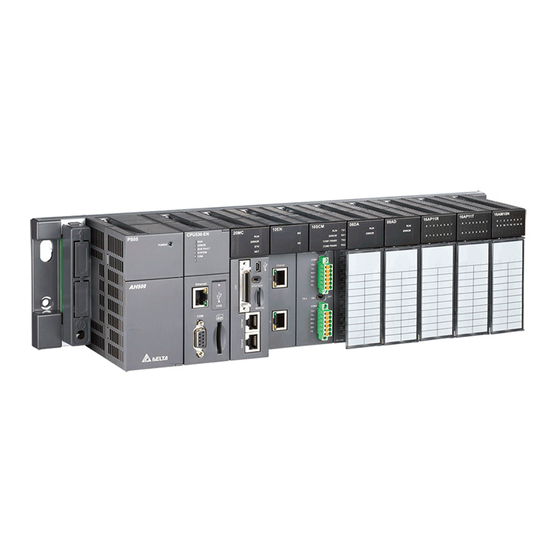
Delta AH500 series Manuals
Manuals and User Guides for Delta AH500 series. We have
6
Delta AH500 series manuals available for free PDF download: Manual, Programming Manual, Hardware Operation Manual, Operation Manual, Hardware Manual, Quick Start Manual
Delta AH500 series Manual (780 pages)
Brand:
Delta
| Category:
Control Unit
| Size: 24.45 MB
Table of Contents
Table of Contents
5
AH500 Module Manual
20
Chapter 1 Introduction
21
Specifications
22
General Specifications
22
EMC Standards
22
Emi
22
Ems
22
Conducted Immunity Test
23
Chapter 2 Analog Input Module AH04AD/AH08AD
25
Overview
26
Characteristics
26
Specifications and Functions
26
Specifications
26
Profile
28
Dimensions
29
Arrangement of Terminals
30
Functions
31
Installation
35
Installing a Module
35
Installing a Removable Terminal Block
37
Wiring
40
LED Indicators
43
HWCONFIG in Ispsoft
43
Initial Setting
43
Checking the Version of a Module
46
Monitoring Table
47
Online Mode
49
Importing/Exporting a Parameter File
50
Parameters
51
Troubleshooting
56
Error Codes
56
Troubleshooting Procedure
57
Chapter 3 Analog Output Module AH04DA/AH08DA
61
Specifications
61
Profile
62
Dimensions
63
Arrangement of Terminals
64
Functions
64
Installation
68
Installing a Module
68
Installing a Removable Terminal Block
70
Wiring
73
LED Indicators
75
HWCONFIG in Ispsoft
76
Initial Setting
76
Checking the Version of a Module
79
Monitoring Table
80
Online Mode
81
Importing/Exporting a Parameter File
82
Parameters
84
Troubleshooting
87
Error Codes
87
Troubleshooting Procedure
87
Chapter 4 Analog Input/Output Module AH06XA
89
Overview
90
Characteristics
90
Specifications and Functions
90
Specifications
90
Profile
93
Dimensions
94
Arrangement of Terminals
94
Functions
95
Installation
103
Installing a Module
103
Installing a Removable Terminal Block
104
Wiring
105
LED Indicators
107
HWCONFIG in Ispsoft
107
Initial Setting
107
Checking the Version of a Module
110
Monitoring Table
111
Online Mode
113
Importing/Exporting a Parametr File
114
Importing/Exporting a Parameter File
114
Parameters
115
Troubleshooting
120
Error Codes
120
Troubleshooting Procedure
121
Troubleshooting Procedure
124
Characteristics
125
Specifications
125
Overview
125
Profile
126
Dimensions
127
Arrangement of Terminals
127
Functions
128
Installation
135
Installing a Module
135
Installing a Removable Terminal Block
136
Wiring
137
External Wiring
138
LED Indicators
138
Initial Setting
139
HWCONFIG in Ispsoft
139
Checking the Version of a Module
142
Monitoring Table
143
Online Mode
144
Parameters
146
Troubleshooting
159
Error Codes
159
Troubleshooting Procedure
160
Overview
160
Characteristics
160
Specifications
161
Profile
162
Dimensions
163
Arrangement of Terminals
163
Functions
164
Installation
172
Installing a Module
172
Installing a Removable Terminal Block
173
Wiring
174
LED Indicators
176
HWCONFIG in Ispsoft
176
Initial Setting
176
Checking the Version of a Module
179
Monitoring Table
180
Online Mode
182
Importing/Exporting a Parameter File
183
Parameters
184
Troubleshooting
194
Overview
198
Characteristics
198
Specifications and Functions
199
Specifications
199
Profile
200
Dimensions
201
Arrangement of Terminals
201
Functions
202
Installation
209
Installing a Module
209
Installing a Removable Terminal Block
210
Wiring
211
LED Indicators
212
HWCONFIG in Ispsoft
213
Initial Setting
213
Checking the Version of a Module
216
Monitoring Table
217
Online Mode
219
Parameters
221
Troubleshooting
230
Error Codes
230
Troubleshooting Procedure
232
Introduction
234
Characteristics
234
Specifications
235
Dimensions of AH02HC-5A
235
Specifications for AH02HC-5A
235
Dimensions of AH04HC-5A
236
Specifications for AH04HC-5A
236
Functions of AH02HC-5A/AH04HC-5A
237
Profile of AH02HC-5A
238
Profile of AH04HC-5A
239
Arrangement of Input/Output Terminals
239
External Wiring
240
HWCONFIG in Ispsoft
241
Checking the Firmware Version of a Module
241
Initial Setting
244
Updating Parameters
245
Monitoring Parameters
246
Parameter Table
248
Writing Parameters
249
Descriptions of the Control Registers
250
Operation of a Counter
250
Input Pulse Type
251
Frequency of an Input Pulse
251
Cycle of Reading the Number of Pulses
252
Counting Parameters
252
Operating State of a Counter
260
Number of Input Pulses
261
Error Codes
261
Troubleshooting
262
Error Codes
262
Descriptions of the LED Indicators
262
Introduction
264
Dimensions and Profile
266
Dimensions
266
Profile
267
Port
268
Communication Port
269
Installation and Wiring
270
Installation
270
Control Registers
271
Descriptions of the Control Registers
274
Introduction of the Related Instructions
280
Quick Start
284
Software
291
SCM Project
291
COM Port Setting
291
UD Link (User-Defined Communication)
292
TX Packets and RX Packets
293
Command
295
Sequence
296
Modbus Advance
296
COM Port History
296
Modbus Slave─Connection with Delta Products
298
Modbus Master─Connection with Delta Products
300
Connecting to Ispsoft
308
Rs-485/Rs232
309
Connecting to a Power Meter
309
Error Flags
327
Introduction
332
Functions
332
Specifications
332
Dimensions
333
Profile
333
Port
334
Installation and Wiring
334
Installation
334
Connecting to the Network
335
Registers
335
Functions of the Input Registers
335
Functions of the Output Registers
336
Functions of the Control Registers
337
Introduction of the Related Instructions
345
Introduction of the IEC60870-5-104 Protocol
349
Hwconfig─Network Parameters
354
Setting AH10/15EN-5A through Ispsoft
354
Hwconfig─Function List
355
HWCONFIG─IP Filter Parameters
356
HWCONFIG─I/O Mapping Parameters
356
Hardware Configuration ─ IEC60870-5 Parameters
357
Intelligent Module Configuration ─ NTP
357
Intelligent Module Configuration─Email
358
Intelligent Module Configuration─Data Exchange
360
Intelligent Module Configuration─Snmp
362
Error Codes and Troubleshooting
362
Chapter 10 Devicenet Communication Module AH10DNET
365
Introduction
365
Feature
365
Functions
365
Profile and Outline
366
Profile and Dimensions
366
Parts
367
Devicenet Communication Connector
367
Address Switch
368
Function Switch
368
Seven-Segment Display
368
Installation
369
Installing the Module
369
Connecting to the Devicenet Communication Connector
370
Devicenet Bus Network Topology Structure
370
Choice and Purpose of a Devicenet Terminal Resistor
374
Devicenet Network Supply Power
375
Configuration of AH10DNET-5A
376
Data Mapping Areas
376
Assignment of Mapping Area (in Master Mode)
376
Assignment of Mapping Area (in Slave Mode)
377
Data Flow Direction of Master and Slave
377
Bit-Strobe Command
379
Bit-Strobe Work Principle
379
Network Node Status Display
380
Scan List Node Status Display
380
Scanner Module Status Display
380
Special Operation in Master Mode
381
Master Mode Setting
381
Mapping Areas Setting
385
Extension Baud Rate Setting
391
Advertisement
Delta AH500 series Hardware Operation Manual (681 pages)
Brand:
Delta
| Category:
Controller
| Size: 32.09 MB
Table of Contents
Table of Contents
5
Chapter 1 Introduction
16
Introduction
17
Related Manuals
17
Description of Models
17
Overview
24
Characteristics
26
Chapter 2 Specifications and System Configuration
34
General Specifications
36
Specifications for CPU Modules
37
AH500 Series Basic CPU Modules
37
AH500 Series Advanced CPU Modules
39
AH500 Redundancy CPU Module Specification
41
Profiles
42
Dimensions
46
Basic System Configuration
47
Introduction
47
Configuring a Main Backplane
48
Configuring an Extension Backplane
48
Maximum Extension
48
Specifications for Backplanes
49
General Specifications
49
Profiles
50
Dimensions
54
Specifications for the Power Supply Module
57
General Specifications
57
Profile
58
Dimensions
59
Arrangement of Terminals
60
Specifications for Digital Input/Output Modules
61
General Specifications
61
Profiles
64
Dimensions
73
Arrangement of Input/Output Terminals
78
Specifications for Analog Input/Output Modules
86
General Specifications
86
Profiles
90
Dimensions
92
Arrangement of Input/Output Terminals
93
Specifications for Temperature Measurement Modules
94
Profiles
96
Dimensions
98
Arrangement of Input/Output Terminals
99
Specifications for Network Modules
100
General Specifications
100
Profiles
103
Dimensions
111
Arrangement of Input/Output Terminals
115
Specifications for Motion Control Modules
116
General Specifications
116
Profiles
126
Dimensions
133
Arrangement of Input/Output Terminals
137
Specifications for the Remote I/O Modules
142
General Specifications
142
Profiles
143
Dimensions
147
Space Module and Extension Cables
149
General Specifications
149
Profiles
150
Dimensions
151
Chapter 3 Installing Software
154
Installing and Uninstalling Ispsoft
155
Installing Ispsoft
156
Uninstalling Ispsoft
162
Installing and Uninstalling COMMGR
163
Installing COMMGR
163
Uninstalling COMMGR
166
AH500 Hardware Framework
171
Component Parts of AH500 Hardware
171
Installing Modules on a Main Backplane
174
Installing Modules on an Extension Backplane
175
Connecting a Main Backplane to an Extension Backplane
176
Warning
176
Installation
177
Installation of Modules in a Control Box
177
Mounting a Backplane
177
Installing a Dust Cover
179
Installing a Module
180
Installing a Removable Terminal Block
181
Installing a Wiring Module
184
Connecting Backplanes
185
Connecting a Communication Cable
186
Wiring
187
Connecting Power Cables
188
Precautions
188
Ground
189
Wiring Power Supply Modules
190
Power Consumption
193
Wiring CPU Modules
196
AH500 Basic / Advanced CPU Modules
196
AH500 Redundant CPU Modules
197
Wiring Digital Input/Output Modules
199
Wiring AH16AM10N-5A
199
Wiring AH16AM30N-5A
200
Wiring AH16AR10N-5A
201
Wiring AH16AN01S-5A
202
Wiring AH16AN01R-5A
203
Wiring AH16AN01T-5A
204
Wiring AH16AN01P-5A
205
Wiring AH16AP11R-5A
206
Wiring AH16AP11T-5A
207
Wiring AH16AP11P-5A
208
Wiring AH32AM10N-5A
209
Wiring AH32AM10N-5B
210
Wiring AH32AM10N-5C
211
Wiring AH32AN02T-5A
212
Wiring AH32AN02T-5B
212
Wiring AH32AN02T-5B
213
Wiring AH32AN02T-5C
214
Wiring AH32AN02P-5A
216
Wiring AH32AN02P-5B
216
Wiring AH32AN02P-5B
217
Wiring AH32AN02P-5C
218
Wiring AH64AM10N-5C
220
Wiring AH64AN02T-5C
221
Wiring AH64AN02P-5C
222
Wiring Digital Input/Output Terminals
224
Wiring Digital Input Terminals
224
Wiring Digital Output Terminals
229
Wiring Analog Input/Output Modules
235
Wiring AH04AD-5A/AH08AD-5A
235
Wiring AH08AD-5B
236
Wiring AH04DA-5A/AH08DA-5A
237
Wiring AH08DA-5B
238
Wiring AH08DA-5C
239
Wiring AH06XA-5A
240
Wiring Temperature Measurement Modules
241
Wiring AH04PT-5A
241
Wiring AH08PTG-5A
242
Wiring AH04TC-5A
243
Wiring AH08TC-5A
243
Wiring Network Modules
244
Wiring AH10DNET-5A
244
Wiring AH10EN-5A / AH15EN-5A
245
Wiring AH10SCM-5A
245
Wiring AH15SCM-5A
246
Wiring AH10PFBM-5A/AH10PFBS-5A
246
Wiring AH10COPM-5A
247
Wiring Remote I/O Modules
248
Wiring AHRTU-DNET-5A
248
Wiring AHRTU-PFBS-5A
250
Wiring AHRTU0-ETHN-5A
251
Wiring AHAADP01EF-5A/AHAADP02EF-5A
252
Wiring Motion Control Modules
254
Specifications for Motion Control Modules
254
I/O Extension Cables and External Terminal Modules
265
Wiring AH02HC-5A and AH04HC-5A
266
Wiring AH20MC-5A
283
Introduction of Devices
287
Devise Table
287
Basic Structure of I/O Storages
289
Relation between the PLC Action and the Device Type
289
Latched Areas in the Device Range
290
Functions of Devices
291
Values and Constants
291
Floating-Point Numbers
292
Strings
292
Input Relays
292
Output Relays
292
Auxiliary Relays
293
Special Auxiliary Relays
293
Stepping Relays
293
Timers
293
Counters
294
32-Bit Counters
295
Data Registers
295
Special Data Registers
296
Link Registers
296
Index Registers
296
Assigning I/O Addresses
297
Software-Defined Addresses
298
Start Addresses for Digital Input/Output Modules
298
Start Addresses for Analog Input/Output Modules
299
Start Addresses for Temperature Measurement Modules
300
Start Addresses for Motion Control Modules
301
Start Addresses for Network Modules
302
User-Defined Addresses
303
Start Addresses for Digital Input/Output Modules
303
Start Addresses for Analog Input/Output Modules
303
Start Addresses for Temperature Measurement Modules
304
Start Addresses for Motion Control Modules
304
Start Addresses for Network Modules
305
Chapter 6 Writing a Program
306
Quick Start
307
Example
307
Hardware
307
Program
307
Procedure for Creating a Project in Ispsoft
308
Hardware Configuration
308
Creating a Project
309
Hardware Configuration
310
Configuring a Module
310
Setting the Parameters in a CPU Module and a Module
312
Creating a Program
314
Adding a Ladder Diagram
314
Basic Editing─Creating a Contact and a Coil
316
Basic Editing─Inserting a Network and Typing an Instruction
319
Basic Editing─Selection of a Network and Operation
321
Basic Editing─Connecting a Contact in Parallel
323
Basic Editing─Editing a Comment
324
Basic Editing─Inserting an Applied Instruction
325
Basic Editing-Creating a Comparison Contact and Typing a Constant
327
Writing a Program
328
Checking and Compiling a Program
329
Testing and Debugging a Program
330
Creating a Connection
330
Downloading a Program and Parameters
333
Connection Test
336
Setting a Real-Time Clock
342
Overview of Memory Cards
345
Appearances of Memory Cards
345
Specifications for SD Cards
345
Using a Memory Card
346
Formatting a Memory Card
346
Write Protect Function of a Memory Card
347
Installing and Removing a Memory Card
348
SD Slot in a CPU Module
348
Installing a Memory Card
348
Removing a Memory Card
348
Contents of a Memory Card
349
Initializing a Memory Card
349
Folder Structure in a Memory Card
349
Reading/Writing a Memory Card
350
Backing up the System
350
Restoring the System
351
Introduction of CARD Utility
352
Backup
354
Restoration
358
Chapter 8 Hardware Configuration
363
Hardware Configuration Tool for AH500 Series Modules - HWCONFIG
363
Introduction of the Environment of HWCONFIG
363
Configuring a Module
365
Setting the Parameters in an AH500 Series CPU Module
379
Setting Interrupts
397
Program Architectures
397
Tasks Supported by AH500 Series CPU Modules
398
I/O Interrupts
399
Low Voltage Detection Interrupt
400
Communication Interrupts
400
External Interrupts
401
Timer Interrupts
402
Network Configuration Tool─Nwconfig
405
Introduction of NWCONFIG
405
Delta AH500 series Programming Manual (749 pages)
Brand:
Delta
| Category:
Controller
| Size: 11.04 MB
Table of Contents
Table of Contents
8
Overview
9
Related Manuals
9
Model Description
9
Software
17
Program Editor
17
Program Organization Units and Tasks
19
Introduction of Devices
21
Devise List
21
AH500 Basic CPU Modules (AHCPU500/510/520/530)
21
AH500 Advanced CPU Modules (AHCPU501/511/521/531)
22
Basic Structure of I/O Storages
23
Relation between the PLC Action and the Device Type
23
Latched Areas in the Device Range
24
Functions of Devices
25
Values and Constants
25
Floating-Point Numbers
26
Single-Precision Floating-Point Numbers
26
Double-Precision Floating-Point Numbers
27
Decimal Floating-Point Numbers
28
Strings
28
Input Relays
29
Output Relays
30
Auxiliary Relays
30
Special Auxiliary Relays
31
Refresh Time of Special Auxiliary Relays
57
Stepping Relays
65
Timers
66
Counters
67
32-Bit Counters
69
Data Registers
70
Special Data Registers
71
Refresh Time of Special Data Registers
99
Additional Remarks on Special Auxiliary Relays and Special Data Registers
101
Link Registers
117
Index Registers
117
Instructions
119
Basic Instructions
119
Applied Instructions
119
Instruction Tables
120
Basic Instructions
120
Applied Instructions
121
Applied Instructions (Sorted Alphabetically)
122
Device Tables
123
Lists of Basic Instructions
124
Lists of Applied Instructions
126
Applied Instructions
126
Applied Instructions (Sorted Alphabetically)
153
Composition of Applied Instructions
169
Restrictions on the Use of the Instructions
172
Index Registers
173
Pointer Registers
174
Pointer Registers of Timers
176
Pointer Registers of 16-Bit Counters
177
Pointer Registers of 32-Bit Counters
178
List of Basic Instructions
180
Basic Instructions
181
Comparison Instructions
208
List of Comparison Instructions
208
Explanation of Comparison Instructions
211
Data Conversion Instructions
241
List of Data Conversion Instructions
241
Explanation of Data Conversion Instructions
242
Data Transfer Instructions
279
List of Data Transfer Instructions
279
Explanation of Data Transfer Instructions
280
Jump Instructions
302
List of Jump Instructions
302
Explanation of Jump Instructions
303
Program Execution Instructions
311
List of Program Execution Instructions
311
Explanation of Program Execution Instructions
312
I/O Refreshing Instructions
319
List of I/O Refreshing Instructions
319
Explanation of I/O Refreshing Instructions
320
Logic Instructions
359
List of Logic Instructions
359
Explanation of Logic Instructions
360
Rotation Instructions
383
List of Rotation Instructions
383
Explanation of Rotation Instructions
384
Shift Instructions
402
List of Shift Instructions
402
Explanation of Shift Instructions
403
Data Processing Instructions
428
List of Data Processing Instructions
428
Explanation of Data Processing Instructions
429
Structure Creation Instructions
475
List of Structure Creation Instructions
475
Explanation of Structure Creation Instructions
476
Module Instructions
483
List of Module Instructions
483
Explanation of Module Instructions
484
Floating-Point Number Instructions
489
Advertisement
Delta AH500 series Operation Manual (288 pages)
Motion Controller
Brand:
Delta
| Category:
Controller
| Size: 5.74 MB
Table of Contents
Table of Contents
3
Preface
9
Introduction
10
Applicable Products
10
Related Manuals
10
Navigation between Manuals
11
Chapter 1 Introduction to Motion Control Operation
13
Features of AH Motion
14
Plcopen Based Motion Control Instructions
14
Motion Network Communications
14
AH Motion System Configurations
15
Basic Operating Procedures for Motion Control
16
Specifications of AH Motion CPU
18
General Specifications
18
Motion Control Specifications
20
Chapter 2 Hardware Setup
21
Installation
22
CPU Rack Installation in a Control Panel
22
Mounting a Backplane
22
Installing a Cpu/Module
24
Installing a CPU Module
24
Wiring
26
Basic System Configurations
26
Wiring Power Supply Modules
26
Wiring AH Motion CPU Modules
32
Wiring AH Motion Controller CPU Modules
32
Chapter 3 Software Setup
39
Installing and Uninstalling Ispsoft
40
Installing Ispsoft
41
Uninstalling Ispsoft
44
Installing and Uninstalling COMMGR
46
Installing COMMGR
46
Uninstalling COMMGR
48
Connecting Ispsoft with AH Motion CPU
50
Direct Connection Via USB
50
Direct Connection Via Ethernet
50
Chapter 4 Operating Ispsoft
51
Quick Start
52
Example
52
Hardware
52
Program
53
Procedures for Creating a Project in Ispsoft
53
Creating a Project
54
Hardware Configuration
55
Configuring a Module
55
Setting the Parameters in a CPU and a Module
57
Setting Module Parameters
59
Setting PLC Parameters
66
Creating a Program
68
Adding a Ladder Diagram
69
Basic Editing─Creating a Contact and a Coil
71
Basic Editing─Inserting a Network and Typing an Instruction
74
Basic Editing - Selection of a Network and Operation
76
Basic Editing - Connecting a Contact in Parallel
78
Basic Editing─Editing a Comment
79
Basic Editing─Inserting an Applied Instruction
80
Basic Editing─Creating a Comparison Contact and Typing a Constant
82
Writing a Program
83
Checking and Compiling a Program
84
Testing and Debugging a Program
85
Creating a Connection
85
Downloading a Program and Parameters
88
Connection Test
90
Setting a Real-Time Clock
96
Chapter 5 Understanding Common Devices
100
Introduction
100
Common Devices
100
Functions of Common Devices
100
Device List
100
Latched Devices
102
Input Relays (X)
103
Output Relays (Y)
103
Auxiliary Relays (M)
104
Special Auxiliary Relays (SM/AM)
104
Data Registers (D)
104
Special Data Registers (SR/AR)
105
Link Registers (L)
105
Stepping Relays (S)
105
Timers (T)
105
Counters (C)
107
32-Bit Counters (HC/AC)
108
Index Registers (E)
108
Values and Constants (K, 16#)
109
Floating-Point Numbers (F, DF)
110
Strings ("$")
112
Ethercat Symbols
114
Symbols
114
Application of Symbols
114
Classes
114
Data Types
115
Using Devices, Symbols and Instructions
116
Modifying a Symbol with an Index Register
117
User-Defined Data Type (ENUM)
118
Chapter 6 Understanding Motion Control Devices
121
Motion Control Devices
122
Structures Applicable for Motion Control
122
Parameters for Motion Axes
122
Chapter 7 Motion Control Programming
128
Introduction
128
Program Organization Units and Tasks
128
Motion Control Program
129
Program Architecture and Types in Ispsoft
129
Pous in Ispsoft
130
Managing the Tasks in Ispsoft
130
Motion Control Instructions
131
Function Blocks for AH Motion Controller CPU
131
Axis
133
State Transitions
136
Axis States
136
Axis Group State
137
Buffer Mode
138
Execution of Function Block Instructions
143
The Interface of a Motion Control Function Block
143
Timing Diagram for Input/Outputs
146
Positions
147
Postion Types
147
Applicable Postions for each Axis Type
147
Electronic Cam
147
Introduction of Electronic Cams
147
Operation of an Electronic Cam
148
Initial Setting
149
Setting a Master/Slave Axis and Operating an Electronic Cam
150
Starting/Stopping an Electronic Cam Operating Cyclically
154
Creating Electronic Cam Data
157
Creating a CAM Chart in Ispsoft
157
Application of an Electronic Cam-Using a Rotary Cutter
166
Creating Rotary Cut Data
169
Chapter 8 Memory Card
178
Overview of Memory Cards
178
Appearances of Memory Cards
178
Specifications for SD Cards
178
Using a Memory Card
179
Formatting a Memory Card
179
Delta AH500 series Hardware Manual (229 pages)
Programmable logic controllers
Brand:
Delta
| Category:
Computer Hardware
| Size: 10.13 MB
Table of Contents
Chapter 2 Installing the Hardware
16
Overview
3
Characteristics
8
Table of Contents
16
AH500 Hardware Framework
17
Component Parts of the AH500 Hardware
17
Necessary Components
17
Accessories
19
Installing Modules on a Main Backplane
22
Installing Modules on an Extension Backplane
23
Connecting a Main Backplane to an Extension Backplane
23
Installation
24
Installation of Modules in a Control Box
24
Mounting a Backplane
24
Installing a Module
27
Installing a Removable Terminal Block
28
Installing a Wiring Module
29
Connecting Backplanes
30
Putting a Communication Cable
31
Warning
24
Chapter 3 Product Specifications
32
General Specifications
34
Specifications for CPU Modules
34
Profiles
36
Dimensions
38
Specifications for Backplanes
38
General Specifications
38
Profiles
39
Dimensions
41
Specifications for the Power Supply Module
43
General Specifications
43
Profile
43
Dimensions
44
Arrangement of Terminals
44
Specifications for Digital Input/Output Modules
45
General Specifications
45
Profiles
47
Dimensions
53
Arrangement of Input/Output Terminals
58
Specifications for Analog Input/Output Modules
63
General Specifications
63
Profiles
67
Dimensions
68
Arrangement of Input/Output Terminals
69
Specifications for Temperature Measurement Modules
70
General Specifications
70
Profiles
71
Dimensions
72
Arrangement of Input/Output Terminals
72
Specifications for Network Modules
73
General Specifications
73
Profiles
74
Dimensions
78
Arrangement of Input/Output Terminals
79
Specifications for Motion Control Modules
80
General Specifications
80
Profiles
90
Dimensions
96
Arrangement of Input/Output Terminals
99
Specifications for the RTU Module
101
General Specifications
101
Profiles
102
Dimensions
103
Space Module and Extension Cables
104
Chapter 4 Addressing
106
I/O Addressing
107
Software-Defined Addresses
107
Start Addresses for Digital Input/Output Modules
107
Start Addresses for Analog Input/Output Modules
108
Start Addresses for Temperature Measurement Modules
109
Start Addresses for Motion Control Modules
109
Start Addresses for Network Modules
110
User-Defined Addresses
110
Start Addresses for Digital Input/Output Modules
110
Start Addresses for Analog Input/Output Modules
111
Start Addresses for Temperature Measurement Modules
112
Start Addresses for Motion Control Modules
112
Start Addresses for Network Modules
113
Chapter 5 Wiring
114
Wiring
116
Power Wiring
117
Precautions
117
Ground
118
Wiring the Power Supply Module
118
Power Consumption
120
Wiring CPU Modules
122
Wiring Digital Input/Output Modules
123
Wiring AH16AM10N-5A
123
Wiring AH16AM30N-5A
124
Wiring AH16AN01T-5A
125
Wiring AH16AN01P-5A
126
Wiring AH16AN01R-5A
127
Wiring AH16AN01S-5A
128
Wiring AH16AP11T-5A
129
Wiring AH16AP11P-5A
130
Wiring AH16AP11R-5A
131
External Terminal Module for AH32AM10N-5B
131
External Terminal Modules for AH32AN02T-5B
132
External Terminal Modules for AH32AN02P-5B
132
External Terminal Module for AH64AM10N-5C
133
External Terminal Module for AH64AN02T-5C
133
External Terminal Module for AH64AN02P-5C
134
Wiring Digital Input/Output Terminals
134
Wiring Digital Input Terminals
134
Sinking and Sourcing
134
Relay Type
134
Open-Collector Input Type
135
Two-Wire Proximity Switch
135
Three-Wire Switch
136
Optoelectronic Switch
136
Voltage Input (120~240 V AC)
137
Wiring Digital Output Terminals
137
Output Circuits
137
Relay Output Circuit
138
Transistor Output Circuit
140
TRIAC Output Circuit
142
Wiring Analog Input/Output Modules
143
Wiring AH04AD-5A
143
Wiring AH08AD-5B
144
Wiring AH04DA-5A
144
Wiring AH08DA-5B
145
Wiring AH06XA-5A
146
Wiring Temperature Measurement Modules
147
Wiring AH04PT-5A
147
Wiring AH04TC-5A
148
Wiring AH08TC-5A
148
Wiring Network Modules
149
Wiring AH10DNET-5A
149
Devicenet Connector
149
Joining the Cable to the Devicenet Connector
149
Installing the Devicenet Connector
150
Wiring AH10EN-5A
150
Wiring AH10SCM-5A
150
Wiring the RTU Module
151
Wiring AHRTU-DNET-5A
151
Devicenet Connector
151
Joining the Cable to the Devicenet Connector
151
Installing the Devicenet Connector
152
Wiring Motion Control Modules
152
Specifications for Motion Control Modules
152
I/O Extension Cables and External Terminal Modules
161
Wiring AH02HC-5A and AH04HC-5A
163
External Wiring
164
Transistor Output Circuit
165
Wiring the Differential Inputs
165
Wiring AH05PM-5A and AH10PM-5A
167
Wiring the Input Terminals
169
Wiring the Output Terminals
171
Wiring AH10PM-5A and an Inferior Servo Drive
173
Wiring AH20MC-5A
178
Transistor Output Circuit
179
Wiring the Differential Input Terminals
179
Delta AH500 series Quick Start Manual (61 pages)
programmable logic controller
Brand:
Delta
| Category:
Controller
| Size: 6.96 MB
Table of Contents
Chapter 2 Programming
12
Slave
7
Slave
8
System Planning
9
Operation of the Cpu Module
10
Table of Contents
12
Preparations
13
Hardware
13
Software
14
Tools and Materials
14
Installation
14
Installing Modules
14
Installing Removable Terminal Blocks
15
Wiring
17
Wiring the Power Supply Module
18
Wiring the Digital Input Module
20
Wiring the Digital Output Module
20
Wiring the Analog Input/Output Module
21
Supplying Power
21
Exemplification
22
Creating Projects
23
Hardware Configuration
25
Creating Global Symbols
30
Creating Function Blocks
31
Creating Main Programs
40
Chapter 3 Downloading and Monitoring the Program
46
Manuals
46
Setting COMMGR
50
Enabling COMMGR
50
Opening the COMMGR Window
50
Setting the Communication
50
Downloading the Program
51
Setting the Communication
51
Downloading the Hardware Configuration
52
Downloading the Program
53
Operation of the CPU Module
53
Monitoring and Debugging the Program
54
Monitoring the Program
54
Debugging the Program and the System
58
Advertisement
Related Products
Delta AHBP06M1-5A
Delta AHBP12M1-5A
Delta AH64AM10N-5C
Delta AH16AN01P-5A
Delta AH64AN02P-5C
Delta AH16AN01S-5A
Delta AH04DA-5A
Delta AH04HC-5A
Delta AH05PM-5A
Delta AH10EN-5A Series
Delta Categories
Plumbing Product
Kitchen & Bath Fixtures
Bathroom Fixtures
Saw
Power Supply
More Delta Manuals
Login
Sign In
OR
Sign in with Facebook
Sign in with Google
Upload manual
Upload from disk
Upload from URL