Juniper SRX 5600 Hardware Manual
Services gateway
Hide thumbs
Also See for SRX 5600:
- Hardware manual (483 pages) ,
- Installation and initial configuration manual (205 pages) ,
- Manual (34 pages)

Related Manuals for Juniper SRX 5600


Summary of Contents for Juniper SRX 5600
-
Page 1: Hardware Guide
SRX 5600 Services Gateway Hardware Guide Juniper Networks, Inc. 1194 North Mathilda Avenue Sunnyvale, California 94089 408-745-2000 www.juniper.net Part Number: 530-029951-01, Revision 01... - Page 2 Products made or sold by Juniper Networks or components thereof might be covered by one or more of the following patents that are owned by or licensed to Juniper Networks: U.S. Patent Nos. 5,473,599, 5,905,725, 5,909,440, 6,192,051, 6,333,650, 6,359,479, 6,406,312, 6,429,706, 6,459,579, 6,493,347, 6,538,518, 6,538,899, 6,552,918, 6,567,902, 6,578,186, and 6,590,785.
- Page 3 (g) distribute any key for the Software provided by Juniper to any third party; (h) use the Software in any manner that extends or is broader than the uses purchased by Customer from Juniper or an authorized Juniper reseller;...
- Page 4 (or services are accessed by) the Software shall be a third party beneficiary with respect to this Agreement, and such licensor or vendor shall have the right to enforce this Agreement in its own name as if it were Juniper. In addition, certain third party software may be provided with the Software and is subject to the accompanying license(s), if any, of its respective owner(s).
- Page 5 Software, whether oral or written (including any inconsistent terms contained in a purchase order), except that the terms of a separate written agreement executed by an authorized Juniper representative and Customer shall govern to the extent such terms are inconsistent or conflict with terms contained herein.
-
Page 7: Table Of Contents
JUNOS Software Documentation for J-series Services Routers and SRX-series Services Gateways ................xxiii Obtaining Documentation ................xxv Documentation Feedback ................xxv Requesting Technical Support ..............xxvi Part 1 SRX 5600 Services Gateway Overview Chapter 1 Services Gateway Overview Services Gateway Description ................3 Component Redundancy .................4 Chapter 2 Hardware Components Services Gateway Chassis ................5... - Page 8 SRX 5600 Services Gateway Hardware Guide Routing Engine ....................19 Routing Engine Components ..............20 Routing Engine Interface Ports and Status Indicators ......21 Routing Engine Boot Sequence ...............22 Cable Management System ................22 Craft Interface ....................23 Alarm LEDs and Alarm Cutoff/Lamp Test Button ........24 Host Subsystem LEDs ................25...
- Page 9 Table of Contents Chapter 6 Installing the Mounting Hardware Installing the Mounting Hardware for a Rack or Cabinet .......49 Removing the Mounting Brackets for Center-Mounting the Device ....51 Chapter 7 Installing the Services Gateway Safety Requirements, Warnings, and Guidelines ...........53 Installing the Services Gateway Using a Mechanical Lift ........53 Tools Required ..................54 Installing the Services Gateway Using a Lift ..........54...
- Page 10 SRX 5600 Services Gateway Hardware Guide Maintaining the Host Subsystem ..............81 Maintaining IOCs and SPCs ................84 Maintaining IOC Cables .................85 Handling and Storing Cards ................86 Holding a Card ..................87 Storing a Card ..................89 Maintaining the Power Supplies ..............90 Chapter 12 Troubleshooting Hardware Components Overview of Troubleshooting Resources ............91...
- Page 11 Table of Contents Replacing a Routing Engine ..............112 Removing a Routing Engine ............113 Installing a Routing Engine .............114 Replacing Connections to Routing Engine Interface Ports .....115 Replacing the Management Ethernet Cable ........115 Replacing the Console or Auxiliary Cable ........116 Replacing IOCs ....................116 Removing an IOC .................116 Installing an IOC ...................118 Replacing Flex IOCs and Port Modules ............120...
- Page 12 SRX 5600 Services Gateway Hardware Guide Installation Safety Guidelines and Warnings .........154 Chassis Lifting Guidelines ...............154 Installation Instructions Warning ............154 Rack-Mounting Requirements and Warnings ........155 Ramp Warning ................158 Laser and LED Safety Guidelines and Warnings ........159 General Laser Safety Guidelines ............159 Class 1 Laser Product Warning ............159...
- Page 13 Installing the Cable Management System ............212 Appendix G Contacting Customer Support and Returning Hardware Locating Component Serial Numbers ............215 SRX 5600 Chassis Serial Number Label ..........216 SCB Serial Number Label ..............217 IOC and SPC Serial Number Label ............218 xiii Table of Contents...
- Page 14 SRX 5600 Services Gateway Hardware Guide Power Supply Serial Number Labels ............219 Routing Engine Serial Number Label .............220 Contacting Customer Support ..............220 Information You Might Need to Supply to JTAC ........220 Return Procedure ..................221 Tools and Parts Required ................222 Packing the Services Gateway for Shipment ..........222 Packing Components for Shipment .............223...
- Page 15 Figure 7: Flex IOC with Port Modules ............11 Figure 8: Port Modules Supported on the Flex IOC ........12 Figure 9: Typical SPC ..................15 Figure 10: SPCs Installed Horizontally in the SRX 5600 Services Gateway ..15 Figure 11: SCB ....................18 Figure 12: Routing Engine ................20 Figure 13: USB Memory Device in a Routing Engine ........21...
- Page 16 SRX 5600 Services Gateway Hardware Guide Figure 29: Installing the Cable Management System ........56 Chapter 8 Connecting the Services Gateway Figure 30: Routing Engine Management Ports ..........58 Figure 31: Routing Engine Ethernet Cable Connector ........58 Figure 32: Console and Auxiliary Cable Connector ........59 Figure 33: Alarm Relay Contacts ..............60...
- Page 17 Appendix G Contacting Customer Support and Returning Hardware Figure 87: Serial Number ID Label ..............216 Figure 88: SRX 5600 Chassis Serial Number Label ........217 Figure 89: SCB Serial Number Label ............218 Figure 90: IOC and SPC Serial Number Label ..........218 Figure 91: AC Power Supply Serial Number Label ........219...
- Page 18 SRX 5600 Services Gateway Hardware Guide xviii List of Figures...
- Page 19 Table 2: Text and Syntax Conventions ............xxii Table 3: JUNOS Software Documentation for J-series Services Routers and SRX-series Services Gateways ..............xxiv Part 1 SRX 5600 Services Gateway Overview Chapter 2 Hardware Components Table 4: 4-port 10–Gigabit Ethernet IOC LEDs ..........10 Table 5: 40-port Gigabit Ethernet IOC LEDs ...........10...
- Page 20 SRX 5600 Services Gateway Hardware Guide Part 3 Hardware Maintenance, Replacement, and Troubleshooting Procedures Chapter 13 Replacing Hardware Components Table 26: Field-Replaceable Units ..............100 Table 27: Tools and Parts Required .............100 Part 4 Appendixes Appendix B Physical Specifications Table 28: Physical Specifications ..............181...
-
Page 21: About This Guide
About This Guide This preface provides the following guidelines for using the SRX 5600 Services Gateway Hardware Guide: Objectives on page xxi Audience on page xxi Documentation Conventions on page xxii JUNOS Software Documentation for J-series Services Routers and SRX-series... -
Page 22: Table 1: Notice Icons
SRX 5600 Services Gateway Hardware Guide Documentation Conventions Table 1 on page xxii defines the notice icons used in this guide. Table 1: Notice Icons Icon Meaning Description Informational note Indicates important features or instructions. Caution Indicates a situation that might result in loss of data or hardware damage. -
Page 23: About This Guide
Table 3 on page xxiv lists the software manuals and release notes for J-series Services Routers running JUNOS software with enhanced services and SRX-series services gateways running JUNOS software. All documents are available at http://www.juniper.net/techpubs/ xxiii JUNOS Software Documentation for J-series Services Routers and SRX-series Services Gateways... - Page 24 SRX 5600 Services Gateway Hardware Guide Table 3: JUNOS Software Documentation for J-series Services Routers and SRX-series Services Gateways Book Description All Platforms JUNOS Software Interfaces and Routing Explains how to configure J-series and SRX-series interfaces Configuration Guide for basic IP routing with standard routing protocols, ISDN service, firewall filters (access control lists), and class-of-service (CoS) traffic classification.
-
Page 25: Table 3: Junos Software Documentation For J-Series Services Routers And
Juniper Networks Web site at http://www.juniper.net/ To order printed copies of this guide and other Juniper Networks technical documents, or to order a documentation CD, which contains this guide, contact your sales representative. - Page 26 7 days a week, 365 days a year. Self-Help Online Tools and Resources For quick and easy problem resolution, Juniper Networks has designed an online self-service portal called the Customer Support Center (CSC) that provides you with the following features: Find CSC offerings: http://www.juniper.net/customers/support/...
-
Page 27: Part 1 Srx 5600 Services Gateway Overview
Part 1 SRX 5600 Services Gateway Overview Services Gateway Overview on page 3 Hardware Components on page 5 SRX 5600 Services Gateway Overview... -
Page 28: Phillips (+) Screwdrivers, Numbers 1 And
SRX 5600 Services Gateway Hardware Guide SRX 5600 Services Gateway Overview... -
Page 29: Services Gateway Overview
The SRX 5600 services gateway is a high-performance, highly-scalable, carrier-class security device with multi-processor architecture. The SRX 5600 services gateway is eight rack units (RU) tall. Three of these devices can be stacked in a single floor-to-ceiling rack, for increased port density per unit of floor space. -
Page 30: Component Redundancy
SRX 5600 Services Gateway Hardware Guide Management. This group of signals provides for low-level status diagnostic support. Component Redundancy The following major hardware components are redundant: SCBs—The host subsystem consists of a Routing Engine installed in an SCB. The device must have one host subsystem installed. You can install a second SCB for redundancy. -
Page 31: Hardware Components
Chapter 2 Hardware Components Services Gateway Chassis on page 5 Midplane on page 7 I/O Cards on page 8 Flex I/O Cards and Port Modules on page 11 Services Processing Cards on page 14 Host Subsystem on page 17 Switch Control Board on page 17 Routing Engine on page 19 Cable Management System on page 22 Craft Interface on page 23... -
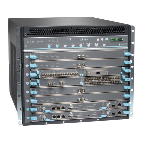
Page 32: Figure 1: Front View Of A Fully Configured Services Gateway Chassis
SRX 5600 Services Gateway Hardware Guide Figure 1: Front View of a Fully Configured Services Gateway Chassis Figure 2: Rear View of a Fully Configured AC-Powered Services Gateway Chassis Services Gateway Chassis... -
Page 33: Midplane
Chapter 2: Hardware Components Figure 3: Rear View of a Fully Configured DC-Powered Services Gateway Chassis Midplane The midplane is located toward the rear of the chassis and forms the rear of the card cage (see Figure 4 on page 8). IOCs, SPCs, and SCBs install into the midplane from the front of the chassis, and the power supplies install into the midplane from the rear of the chassis. -
Page 34: I/O Cards
If a slot is not occupied by a card, a blank panel must be installed to shield the empty slot and to allow cooling air to circulate properly through the services gateway. Figure 5 on page 9 shows the IOCs supported on the SRX 5600 services gateways. I/O Cards... -
Page 35: Ioc Components
Chapter 2: Hardware Components Figure 5: IOCs Supported On the SRX 5600 Figure 6: IOCs Installed Horizontally in the SRX 5600 IOC Components Each IOC consists of the following components: IOC cover, which functions as a ground plane and a stiffener. -
Page 36: Table 4: 4-Port 10-Gigabit Ethernet Ioc Leds
SRX 5600 Services Gateway Hardware Guide Two interfaces from the SCBs that enable the boards to be powered on and controlled. Physical IOC connectors. Packet Forwarding Engines. Midplane connectors and power circuitry. Processor subsystem, which includes a 1.2-GHz CPU, system controller, and 1 GB of SDRAM. -
Page 37: Flex I/O Cards And Port Modules
Chapter 2: Hardware Components Flex I/O Cards and Port Modules Flex I/O Cards (flex IOCs) are IOCs with two slots, which accept port modules that add Ethernet ports to your services gateway. A flex IOC with installed port modules functions in the same way as a regular IOC, but allows greater flexibility in adding different types of Ethernet ports to your services gateway. -
Page 38: Flex Ioc Components
SRX 5600 Services Gateway Hardware Guide You use port modules and flex IOCs to add different combinations of SFP, XFP, and TX ports to your services gateway to suit the specific needs of your network. The available port modules are shown in Figure 8 on page 12. See “Installing a Port Module”... -
Page 39: Port Module Components
Chapter 2: Hardware Components Midplane connectors and power circuitry Processor subsystem, including a 1.2-GHz CPU, a system controller, and 1 GB of SDRAM Port Module Components Each port module consists of the following components: Port module cover, which functions as a ground plane and a stiffener Physical I/O port connectors Ethernet switch Online... -
Page 40: Services Processing Cards
If a slot is not occupied by a card, a blank panel must be installed to shield the empty slot and to allow cooling air to circulate properly through the device. Figure 9 on page 15 shows a typical SPC supported on the SRX 5600 services gateways. -
Page 41: Spc Components
Chapter 2: Hardware Components Figure 9: Typical SPC Figure 10: SPCs Installed Horizontally in the SRX 5600 Services Gateway SPC Components Each SPC consists of the following components: SPC cover, which functions as a ground plane and a stiffener. Two Chassis Cluster Control ports for connecting multiple devices into a redundant chassis cluster. -
Page 42: Table 10: Spc Leds
SRX 5600 Services Gateway Hardware Guide Two Gigabit Ethernet interfaces that allow control information, route information, and statistics to be sent between the Routing Engine and the CPU on the SPCs. Two interfaces from the SCBs that enable the boards to be powered on and controlled. -
Page 43: Host Subsystem
Chapter 2: Hardware Components Table 10: SPC LEDs (continued) Label Color State Description Green On steadily The Chassis Cluster Control port is enabled. ENABLE The Chassis Cluster Control port is disabled. Two LEDs, located on the craft interface above the SPC, display the status of the SPC and are labeled . -
Page 44: Scb Slots
SRX 5600 Services Gateway Hardware Guide Figure 11: SCB SCB Slots You must install at least one SCB in the services gateway as part of a host subsystem. You can install a second SCB for redundancy. The SCBs install horizontally into the front of the chassis in the slots labeled . -
Page 45: Scb Leds
Chapter 2: Hardware Components Control FPGA—Provides the Peripheral Component Interconnect (PCI) interface to the Routing Engine. 1000Base-T Ethernet controller—Provides a 1-Gbps Ethernet link between the Routing Engines. Ethernet switch—Provides 1-Gbps link speeds between the Routing Engine and the IOCs. Circuits for chassis management and control. Power circuits for the Routing Engine and SCB. -
Page 46: Routing Engine Components
SRX 5600 Services Gateway Hardware Guide Figure 12: Routing Engine Routing Engine Components The Routing Engine (shown in Figure 12 on page 20) consists of the following components: CPU—Runs JUNOS software to maintain the services gateway's routing tables and routing protocols. It has a Pentium-class processor. -
Page 47: Routing Engine Interface Ports And Status Indicators
Chapter 2: Hardware Components Figure 13: USB Memory Device in a Routing Engine The Routing Engine has four LEDs that indicate its status. The LEDs, labeled MASTER ONLINE , and FAIL , are located directly on the faceplate of the Routing Engine. Table 12 on page 21 describes the functions of the Routing Engine LEDs. -
Page 48: Routing Engine Boot Sequence
SRX 5600 Services Gateway Hardware Guide —Connects the Routing Engine through an Ethernet connection to a ETHERNET management LAN (or any other device that plugs into an Ethernet connection) for out-of-band management. The port uses an autosensing RJ-45 connector to support10-Mbps or 100-Mbps connections. -
Page 49: Craft Interface
Chapter 2: Hardware Components Figure 14: Cable Management Divider Figure 15: Cable Management System Installed on the Device Craft Interface The craft interface shows you status and troubleshooting information at a glance and lets you perform many system control functions. It is hot-insertable and hot-removable. -
Page 50: Figure 16: Front Panel Of The Craft Interface
SRX 5600 Services Gateway Hardware Guide Online Buttons on page 27 Alarm Relay Contacts on page 27 Figure 16: Front Panel of the Craft Interface NOTE: At least one SCB must be installed in the services gateway for the craft interface to obtain power. -
Page 51: Table 13: Alarm Leds And Alarm Cutoff/Lamp Test Button
Chapter 2: Hardware Components Table 13: Alarm LEDs and Alarm Cutoff/Lamp Test Button Shape Color State Description On steadily Critical alarm LED—Indicates a critical condition that can cause the device to stop functioning. Possible causes include component removal, failure, or overheating. Yellow On steadily Warning alarm LED—Indicates a serious but nonfatal... -
Page 52: Ioc And Spc Leds
SRX 5600 Services Gateway Hardware Guide IOC and SPC LEDs Each IOC and SPC has LEDs on the craft interface that indicate its status. The IOC and SPC LEDs—labeled through —are located along the bottom of the craft interface. Table 16 on page 26 describes the functions of the IOC and SPC LEDs. -
Page 53: Online Buttons
Chapter 2: Hardware Components Online Buttons The craft interface has a row of Online buttons along its lower edge. Each button corresponds to one slot in the card cage. In the current release, the Online buttons are only supported for slots containing I/O cards (IOCs). -
Page 54: Ac Power Supply
SRX 5600 Services Gateway Hardware Guide NOTE: Devices configured with DC power supplies are shipped with a blank panel installed over the power distribution modules. Devices configured with AC power supplies have no blank panel. For information about site power requirements, see “Power Guidelines, Requirements, and Specifications”... -
Page 55: Ac Power Supply Configurations
The SRX 5600 services gateway supports either the low-line (110V) AC power configuration or the high-line (220V) AC power configuration. In the low-line (110 V) AC power configuration, the SRX 5600 contains three or four AC power supplies (see Figure 18 on page 28), located horizontally at the... -
Page 56: Dc Power Supply
SRX 5600 Services Gateway Hardware Guide Table 19: AC Power Supply LEDs (continued) Label Color State Description Power supply is functioning normally. PS FAIL Power supply is not functioning normally and its output voltage is out of regulation limits. Check LEDs for more information. -
Page 57: Dc Power Supply Configurations
Chapter 2: Hardware Components DC Power Supply Configurations In the DC power configuration, the device contains either two or four DC power supplies (see Figure 19 on page 30) located at the rear of the chassis in slots PEM0 through (left to right). -
Page 58: Cooling System
SRX 5600 Services Gateway Hardware Guide Table 21: DC Power Supply LEDs (continued) Label Color State Description Green DC power supply circuit breaker is turned off. BRKR ON Green DC power input is present and the DC power supply circuit breaker is turned on. -
Page 59: Figure 21: Fan Tray
Chapter 2: Hardware Components remaining fans is automatically adjusted to keep the temperature within the acceptable range. If the ambient maximum temperature specification is exceeded and the system cannot be adequately cooled, the Routing Engine shuts down the system by disabling output power from each power supply. - Page 60 SRX 5600 Services Gateway Hardware Guide Cooling System...
-
Page 61: Setting Up The Services Gateway
Part 2 Setting Up the Services Gateway Preparing the Site for Services Gateway Installation on page 37 Installation Overview on page 43 Unpacking the Services Gateway on page 45 Installing the Mounting Hardware on page 49 Installing the Services Gateway on page 53 Connecting the Services Gateway on page 57 Grounding and Providing Power to the Services Gateway on page 63 Configuring the JUNOS Software on page 71... - Page 62 SRX 5600 Services Gateway Hardware Guide Setting Up the Services Gateway...
-
Page 63: Preparing The Site For Services Gateway Installation
Chapter 3 Preparing the Site for Services Gateway Installation This chapter describes how to prepare your site for installation of the SRX 5600 services gateway. It discusses the following topics: Site Preparation Checklist on page 37 Cabinet Requirements on page 38... -
Page 64: Cabinet Requirements
SRX 5600 Services Gateway Hardware Guide Table 22: Site Preparation Checklist (continued) Item or Task For More Information ... Performed By Date Measure distance between external power sources and services gateway installation site. Calculate the optical power budget and optical “Calculating Power Budget for... -
Page 65: Rack Requirements
Cabinets, Racks, Panels, and Associated Equipment (document number EIA-310-D) published by the Electronics Industry Association. You can stack five SRX 5600 services gateways in a rack that has at least 48 U (84 in. or 2.13 m) of usable vertical space. -
Page 66: Clearance Requirements For Airflow And Hardware Maintenance
SRX 5600 Services Gateway Hardware Guide Figure 23: Typical Open-Frame Rack Spacing of Mounting Bracket Holes The device can be mounted in any rack that provides holes or hole patterns spaced at 1 U (1.75 in.) increments. The mounting brackets used to attach the chassis to a rack are designed to fasten to holes spaced at those distances. -
Page 67: Figure 24: Chassis Dimensions And Clearance Requirements
Chapter 3: Preparing the Site for Services Gateway Installation Allow 2.8 in. (7 cm) between the side of the chassis and any non-heat-producing surface such as a wall. For service personnel to remove and install hardware components, there must be adequate space at the front and back of the services gateway. At least 24 in. (61 cm) is required both in front of and behind the device. - Page 68 SRX 5600 Services Gateway Hardware Guide Clearance Requirements for Airflow and Hardware Maintenance...
-
Page 69: Installation Overview
Chapter 4 Installation Overview After you have prepared your installation site as described in “Preparing the Site for Services Gateway Installation” on page 37, you are ready to unpack and install the services gateway. It is important to proceed through the installation process in the following order: Review the safety guidelines explained in “Safety and Regulatory Compliance Information”... - Page 70 SRX 5600 Services Gateway Hardware Guide...
-
Page 71: Unpacking The Services Gateway
Chapter 5 Unpacking the Services Gateway After you have prepared your installation site as described in “Preparing the Site for Services Gateway Installation” on page 37, you are ready to unpack and install the services gateway. It is important to proceed through the installation process in the following order: Review the safety guidelines explained in “Safety and Regulatory Compliance Information”... - Page 72 SRX 5600 Services Gateway Hardware Guide Unpacking the Services Gateway The services gateway is shipped in a wooden crate. A wooden pallet forms the base of the crate. The device chassis is bolted to this pallet. A Getting Started Guide and a cardboard accessory box are also included in the shipping crate.
-
Page 73: Figure 25: Contents Of The Shipping Crate
Chapter 5: Unpacking the Services Gateway Figure 25: Contents of the Shipping Crate Verifying Parts Received A packing list is included in each shipment. Check the parts in the shipment against the items on the packing list. The packing list specifies the part numbers and descriptions of each part in your order. -
Page 74: Table 24: Accessory Box Parts List
SRX 5600 Services Gateway Hardware Guide Table 23: Parts List for a Fully Configured Services Gateway (continued) Component Quantity Small mounting shelf Blank panels for slots without components installed One blank panel for each slot not occupied by a component... -
Page 75: Installing The Mounting Hardware
Chapter 6 Installing the Mounting Hardware The services gateway can be installed in a four-post rack or cabinet or an open-frame rack. Install the mounting hardware on the rack before installing the device. After the mounting hardware is installed, proceed to “Installing the Services Gateway” on page 53 or “Installing the Services Gateway Without a Mechanical Lift”... -
Page 76: Figure 26: Installing The Front Mounting Hardware For A Four-Post Rack Or Cabinet
SRX 5600 Services Gateway Hardware Guide To install the mounting shelf on the front rails of a four-post rack or cabinet, or the rails of an open-frame rack: If needed, install cage nuts in the holes specified in Table 25 on page 49. -
Page 77: Figure 27: Installing The Mounting Hardware For An Open-Frame Rack
Chapter 6: Installing the Mounting Hardware Figure 27: Installing the Mounting Hardware for an Open-Frame Rack Removing the Mounting Brackets for Center-Mounting the Device Two removable mounting brackets are attached to the mounting holes closest to the front of the chassis. You can move the pair of brackets to another position on the side of the chassis for center-mounting the device. - Page 78 SRX 5600 Services Gateway Hardware Guide Two screws are needed for mounting the bracket on the center of the chassis. You do not need the third screw. Tighten the two screws completely. Removing the Mounting Brackets for Center-Mounting the Device...
-
Page 79: Installing The Services Gateway
Chapter 7 Installing the Services Gateway This chapter discusses the following services gateway installation topics: Safety Requirements, Warnings, and Guidelines on page 53 Installing the Services Gateway Using a Mechanical Lift on page 53 Installing the Cable Management System on page 55 Safety Requirements, Warnings, and Guidelines To avoid harm to yourself or the services gateway as you install and maintain it, follow the guidelines for working with and near electrical equipment, as well as the... -
Page 80: Tools Required
SRX 5600 Services Gateway Hardware Guide Tools Required To install the services gateway, you need the following tools: Mechanical lift Phillips (+) screwdriver, number 2 Installing the Services Gateway Using a Lift Before installing the services gateway in the rack, read the safety information in “Chassis Lifting Guidelines”... -
Page 81: Installing The Cable Management System
Chapter 7: Installing the Services Gateway Figure 28: Installing the Services Gateway in the Rack NOTE: This illustration depicts the services gateway being installed in an open-frame rack. For an illustration of the mounting hardware required for a four-post rack or cabinet, see Figure 26 on page 50. -
Page 82: Figure 29: Installing The Cable Management System
SRX 5600 Services Gateway Hardware Guide Figure 29: Installing the Cable Management System Installing the Cable Management System... -
Page 83: Chapter 8 Connecting The Services Gateway
Chapter 8 Connecting the Services Gateway This chapter discusses the following procedures: Tools and Parts Required on page 57 Connecting the Services Gateway to Management and Alarm Devices on page 57 Connecting IOC Cables on page 60 Tools and Parts Required To connect the device to management devices and to power on the device, you need the following tools and parts: Phillips (+) screwdrivers, numbers 1 and 2... -
Page 84: Connecting To A Network For Out-Of-Band Management
SRX 5600 Services Gateway Hardware Guide Figure 30: Routing Engine Management Ports To connect external devices to the Routing Engine management ports, perform the procedures described in the following sections: Connecting to a Network for Out-of-Band Management on page 58... -
Page 85: Figure 32: Console And Auxiliary Cable Connector
Chapter 8: Connecting the Services Gateway Plug one end of the Ethernet cable (Figure 32 on page 59 shows the connector) into the appropriate port on the Routing Engine. Figure 30 on page 58 shows the external device ports on the Routing Engine. The ports labeled connect to the Routing Engine in the left Routing Engine slot ( ), and the ports labeled... -
Page 86: Connecting Ioc Cables
SRX 5600 Services Gateway Hardware Guide Figure 33: Alarm Relay Contacts Connecting IOC Cables Connect the IOCs to the network by plugging in network cables. Follow this procedure (see Figure 34 on page 61, which shows a fiber-optic IOC): Have ready a length of the type of cable used by the IOC. -
Page 87: Figure 34: Attaching A Cable To An Ioc
Chapter 8: Connecting the Services Gateway Figure 34: Attaching a Cable to an IOC Connecting IOC Cables... - Page 88 SRX 5600 Services Gateway Hardware Guide Connecting IOC Cables...
-
Page 89: Grounding And Providing Power To The Services Gateway
Chapter 9 Grounding and Providing Power to the Services Gateway Tools and Parts Required on page 63 Grounding the Services Gateway on page 64 Connecting Power to an AC-Powered Services Gateway on page 64 Powering On an AC-Powered Services Gateway on page 65 Connecting Power to a DC-Powered Services Gateway on page 66 Powering On a DC-Powered Services Gateway on page 68 Powering Off the Services Gateway on page 70... -
Page 90: Connecting Power To An Ac-Powered Services Gateway
SRX 5600 Services Gateway Hardware Guide Grounding the Services Gateway You ground the device by connecting a grounding cable to earth ground and then attaching it to the chassis grounding points using UNC 1/4-20 two screws. You must provide the grounding cables (the cable lugs are supplied with the device). For grounding cable specifications, see “Chassis Grounding”... -
Page 91: Figure 35: Connecting Ac Power To The Services Gateway
Chapter 9: Grounding and Providing Power to the Services Gateway Insert the appliance coupler end of the power cord into the appliance inlet on the power supply. Insert the power cord plug into an external AC power source receptacle. NOTE: Each power supply must be connected to a dedicated AC power feed and a dedicated external circuit breaker. -
Page 92: Connecting Power To An Ac-Powered Services Gateway
SRX 5600 Services Gateway Hardware Guide connecting management devices, see “Connecting the Services Gateway to Management and Alarm Devices” on page 57. Turn on the power to the external management device. Switch the AC switch on each power supply to the on position ( ) and observe the status LEDs on each power supply faceplate. - Page 93 Chapter 9: Grounding and Providing Power to the Services Gateway WARNING: Before performing the following procedure, ensure that power is removed from the DC circuit. To ensure that all power is off, locate the circuit breaker on the panel board that services the DC circuit, switch the circuit breaker to the off position, and tape the switch handle of the circuit breaker in the off position.
-
Page 94: Powering On A Dc-Powered Services Gateway
SRX 5600 Services Gateway Hardware Guide Attach the positive (+) DC source power cable lug to the (return) terminal. Attach the negative (–) DC source power cable lug to the (input) terminal. NOTE: The DC power supplies in must be powered by dedicated... - Page 95 Chapter 9: Grounding and Providing Power to the Services Gateway CAUTION: Do not mix AC and DC power supplies within the same device. Damage to the device might occur. To power on a DC-powered services gateway: Verify that an external management device is connected to one of the Routing Engine ports ( CONSOLE , or...
-
Page 96: Powering Off The Services Gateway
SRX 5600 Services Gateway Hardware Guide NOTE: After powering off a power supply, wait at least 60 seconds before turning it back on. After powering on a power supply, wait at least 60 seconds before turning it off. If the system is completely powered off when you power on the power supply, the Routing Engine boots as the power supply completes its startup sequence. -
Page 97: Chapter 10 Configuring The Junos Software
Chapter 10 Configuring the JUNOS Software The services gateway is shipped with the JUNOS software preinstalled and ready to be configured when the device is powered on. There are three copies of the software: one on a CompactFlash card (if installed) in the Routing Engine, one on the hard disk in the Routing Engine, and one on a USB flash drive that can be inserted into the slot in the Routing Engine faceplate. - Page 98 SRX 5600 Services Gateway Hardware Guide root@> Enter configuration mode. configure [edit] root@# Set the root authentication password by entering either a cleartext password, an encrypted password, or an SSH public key string (DSA or RSA). [edit] root@# set system root-authentication plain-text-password...
- Page 99 Chapter 10: Configuring the JUNOS Software Configure basic security zones and bind them to traffic interfaces. [edit] admin@# set security zones security-zone trust interfaces ge-6/3/5 admin@# set security zones security-zone untrust interfaces ge-6/2/0 Configure basic security policies. [edit] admin@# set security policies from-zone trust to-zone untrust policy policy-name match source-address any destination-address any application any root@# set security policies from-zone trust to-zone untrust policy policy-name then permit...
- Page 100 SRX 5600 Services Gateway Hardware Guide user * { any emergency; file messages { any any; authorization info; file interactive-commands { interactive-commands any; license { autoupdate { url https://ae1.juniper.net/junos/key_retrieval; interfaces { ge-0/0/0 { unit 0; ge-6/2/0 { unit 0 { family inet { address 5.1.1.1/24;...
- Page 101 Chapter 10: Configuring the JUNOS Software policies { from-zone trust to-zone untrust { policy bob { match { source-address any; destination-address any; application any; then { permit; Commit the configuration to activate it on the device. [edit] admin@# commit Optionally, configure additional properties by adding the necessary configuration statements.
- Page 102 SRX 5600 Services Gateway Hardware Guide...
-
Page 103: Hardware Maintenance, Replacement, And Troubleshooting Procedures
Part 3 Hardware Maintenance, Replacement, and Troubleshooting Procedures Maintaining Hardware Components on page 79 Troubleshooting Hardware Components on page 91 Replacing Hardware Components on page 99 Hardware Maintenance, Replacement, and Troubleshooting Procedures... - Page 104 SRX 5600 Services Gateway Hardware Guide Hardware Maintenance, Replacement, and Troubleshooting Procedures...
-
Page 105: Maintaining Hardware Components
This chapter describes how to maintain hardware components installed in the device. Some components, such as the craft interface, require no maintenance. For information about returning a part to Juniper Networks for repair or replacement, see “Contacting Customer Support and Returning Hardware” on page 215. -
Page 106: Maintaining Cooling System Components
SRX 5600 Services Gateway Hardware Guide Inspect the air filter at the left rear of the device, replacing it every 6 months for optimum cooling system performance. Do not run the device for more than a few minutes without the air filter in place. For maintenance instructions, see “Maintaining the Air Filter”... -
Page 107: Maintaining The Host Subsystem
Chapter 11: Maintaining Hardware Components CB 0 Intake 29 degrees C / 84 degrees F CB 0 Exhaust A 30 degrees C / 86 degrees F CB 0 Exhaust B 31 degrees C / 87 degrees F CB 0 ACBC 29 degrees C / 84 degrees F CB 0 SF A 37 degrees C / 98 degrees F... - Page 108 SRX 5600 Services Gateway Hardware Guide Check the LEDs on the craft interface to view information about the status of the Routing Engines. For more information about the LEDs, see “Craft Interface” on page 23. Check the LEDs on the SCB faceplate (see Table 11 on page 19).
- Page 109 Chapter 11: Maintaining Hardware Components 11.3 V bias FPD 11234 mV 11.3 V bias POE 0 11176 mV 11.3 V bias POE 1 11292 mV Bus Revision FPGA Revision CB 1 status: State Online Standby Temperature 40 degrees C / 104 degrees F Power 1 1.2 V 1202 mV...
-
Page 110: Maintaining Iocs And Spcs
SRX 5600 Services Gateway Hardware Guide Maintaining IOCs and SPCs The device can have up to 6 I/O cards (IOCs) and Services Processing Cards (SPCs) mounted horizontally in the card cage at the front of the chassis, as shown in Figure 1 on page 6. -
Page 111: Maintaining Ioc Cables
Chapter 11: Maintaining Hardware Components Total RLDRAM 256 MB Total DDR DRAM 4096 MB Start time: 2007-07-10 12:28:40 PDT Uptime: 1 hour, 33 minutes, 45 seconds Slot 5 information: State Online Temperature 42 degrees C / 107 degrees F Total CPU DRAM 1024 MB Total RLDRAM 256 MB... -
Page 112: Handling And Storing Cards
SRX 5600 Services Gateway Hardware Guide system, because this stresses the cable at the fastening point. Putting fasteners on the loops helps to maintain their shape. Keep the cable connections clean and free of dust and other particles, which can cause drops in the received power level. -
Page 113: Holding A Card
Chapter 11: Maintaining Hardware Components This section discusses how to hold cards in both the vertical and horizontal positions. Regardless of orientation, this section uses the same terms for all four edges of the card (see Figure 37 on page 87): Faceplate—Edge of the card that has connectors to which you connect cables or sockets for SFP or XFP transceivers Connector edge—Edge opposite the faceplate;... -
Page 114: Figure 38: Do Not Grasp The Connector Edge
SRX 5600 Services Gateway Hardware Guide To hold a card vertically: Orient the card so that the faceplate faces you. To verify orientation, confirm that the text on the card is right-side up and the electromagnetic interference (EMI) strip is on the right-hand side. -
Page 115: Storing A Card
Chapter 11: Maintaining Hardware Components Never carry the card by the faceplate with only one hand. Do not rest any edge of a card directly against a hard surface (see Figure 39 on page 89). Do not stack cards. Figure 39: Do Not Rest the Card on an Edge If you must rest the card temporarily on an edge while changing its orientation between vertical and horizontal, use your hand as a cushion between the edge and the surface. -
Page 116: Maintaining The Power Supplies
SRX 5600 Services Gateway Hardware Guide If you must insert the card into a bag by yourself, first lay the card horizontally on a flat, stable surface, sheet metal side down. Orient the card with the faceplate facing you. Carefully insert the card connector edge into the opening of the bag, and pull the bag toward you to cover the card. -
Page 117: Troubleshooting Hardware Components
This chapter describes how to troubleshoot problems with hardware components installed in the services gateway. If you encounter software problems, or problems with hardware components not discussed here, contact the Juniper Networks Technical Assistance Center (JTAC) as described in “Requesting Technical Support” on page xxvi. -
Page 118: Leds
SRX 5600 Services Gateway Hardware Guide For information about using the CLI to display details about alarms generated by interfaces and hardware components, see “Chassis and Interface Alarm Messages” on page 93. For information about using the CLI to troubleshoot the JUNOS software, see the appropriate JUNOS software configuration guide. -
Page 119: Component Leds
Interface alarms—Indicate a problem with a specific network interface. Juniper Networks Technical Assistance Center If you need assistance during troubleshooting, you can contact the Juniper Networks Technical Assistance Center (JTAC) by using the Web or by telephone. See “Requesting Technical Support” on page xxvi. -
Page 120: Troubleshooting The Cooling System
SRX 5600 Services Gateway Hardware Guide Troubleshooting the Cooling System The services gateway cooling system is a fan tray and an air filter, both of which are located vertically in the rear of the chassis (see Figure 1 on page 6). The fan tray contains six fans. -
Page 121: Troubleshooting Iocs
Chapter 12: Troubleshooting Hardware Components Place your hand near the exhaust vents at the side of the chassis to determine whether the fans are pushing air out of the chassis. If all power supplies have failed, the system temperature might have exceeded the threshold, causing the system to shut down. -
Page 122: Troubleshooting Spcs
SRX 5600 Services Gateway Hardware Guide Start time: 2007-07-10 12:28:33 PDT Uptime: 1 hour, 33 minutes, 52 seconds Slot 1 information: State Online Temperature 43 degrees C / 109 degrees F Total CPU DRAM 1024 MB Total RLDRAM 256 MB... -
Page 123: Troubleshooting The Power System
Chapter 12: Troubleshooting Hardware Components Empty Online 1024 For more detailed output, add the option. The following example does not detail specify a slot number, which is optional: user@host> show chassis fpc detail Slot 0 information: State Online Temperature 41 degrees C / 105 degrees F Total CPU DRAM 1024 MB Total RLDRAM... - Page 124 Replace the power supply with a spare, as described in “Replacing Power System Components” on page 133. If you cannot determine the cause of the problem or need additional assistance, see “Juniper Networks Technical Assistance Center” on page 93. Troubleshooting the Power System...
-
Page 125: Replacing Hardware Components
Cold-swap-only FRUs—You must power off the device in order to remove, replace, or add these components. Table 26 on page 100 lists the FRUs for the SRX 5600 services gateway. Field-Replaceable Units (FRUs) -
Page 126: Tools And Parts Required
SRX 5600 Services Gateway Hardware Guide Table 26: Field-Replaceable Units Hot-removable and hot-insertable FRUs Hot-pluggable FRUs Cold-swap-only FRUs Air filter I/O cards(IOCs) Routing Engine Fan tray Flex I/O cards (flex IOCs) Switch Control Boards (SCBs) Craft interface Port modules Services Processing Cards (SPCs) -
Page 127: Replacing The Craft Interface
Chapter 13: Replacing Hardware Components Table 27: Tools and Parts Required (continued) Tool or part Components Electrostatic discharge (ESD) grounding wrist strap Flat-blade (–) screwdriver Cables and connectors Phillips (+) screwdrivers, numbers 1 Air filter and 2 Routing Engine Craft interface Cables and connectors Fan tray Rubber safety cap... -
Page 128: Figure 41: Removing The Craft Interface
SRX 5600 Services Gateway Hardware Guide Removing the Craft Interface To remove the craft interface (see Figure 41 on page 102): Attach an electrostatic discharge (ESD) grounding strap to your bare wrist and connect the strap to one of the ESD points on the chassis. For more information about ESD, see “Preventing Electrostatic Discharge Damage”... -
Page 129: Disconnecting The Alarm Relay Wires
Chapter 13: Replacing Hardware Components Tighten the screws on the left and right corners of the craft interface faceplate. Reattach any external devices connected to the craft interface. Figure 42: Installing a Craft Interface Replacing Alarm Relay Wires The alarm relay wires connect external alarm-reporting devices to the YELLOW relay contacts on the craft interface. -
Page 130: Connecting The Alarm Relay Wires
SRX 5600 Services Gateway Hardware Guide Using the 2.5-mm flat-blade screwdriver, loosen the small screws on the side of the terminal block. Remove existing wires from the slots in the front of the block. Connecting the Alarm Relay Wires To connect the alarm relay wires between a services gateway and an alarm-reporting... -
Page 131: Figure 44: Removing The Fan Tray
Chapter 13: Replacing Hardware Components WARNING: To avoid injury, keep tools and your fingers away from the fans as you slide the fan tray out of the chassis. The fans might still be spinning. Press the latch located on the inside of the fan tray to release it from the chassis. Place one hand under the fan tray to support it and pull the fan tray completely out of the chassis. -
Page 132: Removing An Air Filter
SRX 5600 Services Gateway Hardware Guide Figure 45: Installing the Fan Tray Replacing the Air Filter The services gateway has one air filter that installs vertically in the rear of the chassis. The air filter is hot-insertable and hot-removable. The air filter is located in the rear of the chassis on the left side. The air filter weighs approximately 1 lb (0.5 kg). -
Page 133: Figure 46: Removing The Air Filter
Chapter 13: Replacing Hardware Components To remove the air filter (see Figure 46 on page 107): Attach an electrostatic discharge (ESD) grounding strap to your bare wrist and connect the strap to one of the ESD points on the chassis. For more information about ESD, see “Preventing Electrostatic Discharge Damage”... -
Page 134: Replacing Host Subsystem Components
SRX 5600 Services Gateway Hardware Guide Figure 47: Installing the Air Filter Replacing Host Subsystem Components To replace a host subsystem, use the following procedures: Taking the Host Subsystem Offline on page 108 Replacing an SCB on page 109 Replacing a Routing Engine on page 112... -
Page 135: Operating And Positioning The Scb Ejectors
Chapter 13: Replacing Hardware Components NOTE: The SCB might continue forwarding traffic for approximately 5 minutes after request system halt command has been issued. Wait until a message appears on the console confirming that the operating system has halted. For more information about the command, see the JUNOS System Basics and Services Command Reference. -
Page 136: Figure 48: Removing An Scb
SRX 5600 Services Gateway Hardware Guide Removing an SCB To remove an SCB (see Figure 48 on page 110): NOTE: The SCB and Routing Engine are removed as a unit. You can also remove the Routing Engine separately. Power off the device. See “Powering Off the Services Gateway” on page 70. - Page 137 Chapter 13: Replacing Hardware Components Attach an electrostatic discharge (ESD) grounding strap to your bare wrist and connect the strap to one of the ESD points on the chassis. For more information about ESD, see “Preventing Electrostatic Discharge Damage” on page 152. Power off the device as described in “Powering Off the Services Gateway”...
-
Page 138: Replacing A Routing Engine
SRX 5600 Services Gateway Hardware Guide Power 1 1.2 V 1205 mV 1.5 V 1508 mV 1.8 V 1817 mV 2.5 V 2507 mV 3.3 V 3306 mV 5.0 V 5053 mV 12.0 V 12200 mV 1.25 V 1256 mV 3.3 V SM3... -
Page 139: Figure 50: Removing A Routing Engine
Chapter 13: Replacing Hardware Components Removing a Routing Engine CAUTION: Before you replace a Routing Engine, you must power off the device. See “Powering Off the Services Gateway” on page 70. To remove a Routing Engine (see Figure 50 on page 113): Power off the device. -
Page 140: Installing A Routing Engine
SRX 5600 Services Gateway Hardware Guide Installing a Routing Engine To install a Routing Engine into an SCB (see Figure 51 on page 115): If you have not already done so, power off the device. See “Powering Off the Services Gateway” on page 70. -
Page 141: Replacing Connections To Routing Engine Interface Ports
Chapter 13: Replacing Hardware Components Figure 51: Installing a Routing Engine Replacing Connections to Routing Engine Interface Ports The ports on the Routing Engine connect it to external management devices (see Figure 52 on page 115). Figure 52: Routing Engine Interface Ports To replace the cables that connect to the ports, perform the procedures described in the following sections: Replacing the Management Ethernet Cable on page 115... -
Page 142: Replacing Iocs
SRX 5600 Services Gateway Hardware Guide Plug one end of the replacement cable into the port. Figure 52 on ETHERNET page 115 shows the external device ports on the Routing Engine. Plug the other end of the cable into the network device. - Page 143 Chapter 13: Replacing Hardware Components To remove an IOC (see Figure 54 on page 118): Have ready a replacement IOC or blank panel and an antistatic mat for the IOC. Also have ready rubber safety caps for each IOC you are removing that uses an optical interface.
-
Page 144: Figure 54: Removing An Ioc
SRX 5600 Services Gateway Hardware Guide Place one hand around the front of the IOC and the other hand under it to support it. Slide the IOC completely out of the chassis, and place it on the antistatic mat or in the electrostatic bag. - Page 145 Chapter 13: Replacing Hardware Components Identify the slot on the services gateway where it will be installed. Verify that each fiber-optic transceiver is covered with a rubber safety cap. If it does not, cover the transceiver with a safety cap. Orient the IOC so that the faceplate faces you.
-
Page 146: Replacing Flex Iocs And Port Modules
SRX 5600 Services Gateway Hardware Guide CAUTION: After the LED turns green, wait at least 30 seconds before removing the IOC again, removing an IOC from a different slot, or inserting an IOC in a different slot. You can also verify that the IOC is functioning correctly by issuing the... -
Page 147: Removing A Flex Ioc
Chapter 13: Replacing Hardware Components replacing a flex IOC or port module, review the information in “Handling and Storing Cards” on page 86. To replace a flex IOC or port module, use the following procedures: Removing a Flex IOC on page 121 Installing a Flex IOC on page 123 Removing a Port Module on page 124 Installing a Port Module on page 126... -
Page 148: Figure 57: Removing A Flex Ioc
SRX 5600 Services Gateway Hardware Guide CAUTION: The weight of the flex IOC is concentrated in the back end. Be prepared to accept the full weight—up to 13.1 lb (5.9 kg)—as you slide the flex IOC out of the chassis. -
Page 149: Figure 58: Installing A Flex Ioc
Chapter 13: Replacing Hardware Components Installing a Flex IOC NOTE: Your services gateway must be running JUNOS version 9.5R1 or later in order to recognize flex IOCs and port modules. To install a flex IOC (see Figure 58 on page 123): Attach an electrostatic discharge (ESD) grounding strap to your bare wrist and connect the strap to one of the ESD points on the chassis. - Page 150 SRX 5600 Services Gateway Hardware Guide For more information about the command, see the JUNOS System Basics and Services Command Reference. CAUTION: After the LED turns green, wait at least 30 seconds before removing the IOC again, removing an IOC from a different slot, or inserting an IOC in a different slot.
-
Page 151: Figure 59: Removing A Port Module
Chapter 13: Replacing Hardware Components CAUTION: Do not leave a fiber-optic transceiver uncovered except when inserting or removing cable. The safety cap keeps the port clean and prevents accidental exposure to laser light. CAUTION: Avoid bending fiber-optic cable beyond its minimum bend radius. An arc smaller than a few inches in diameter can damage the cable and cause problems that are difficult to diagnose. -
Page 152: Figure 60: Installing A Port Module
SRX 5600 Services Gateway Hardware Guide Installing a Port Module To install a port module (see Figure 60 on page 126): Attach an electrostatic discharge (ESD) grounding strap to your bare wrist and connect the strap to one of the ESD points on the chassis. For more information about ESD, see “Preventing Electrostatic Discharge Damage”... -
Page 153: Replacing Spcs
Chapter 13: Replacing Hardware Components Insert the appropriate cables into the cable connector ports on each port module. Secure the cables so that they are not supporting their own weight. Place excess cable out of the way in a neatly coiled loop, using the cable management system. Placing fasteners on a loop helps to maintain its shape. - Page 154 SRX 5600 Services Gateway Hardware Guide Removing an SPC An SPC weighs up to 13.1 lb (5.9 kg). Be prepared to accept its full weight. To remove an SPC (see Figure 61 on page 129): Have ready a replacement SPC or blank panel and an antistatic mat for the SPC.
-
Page 155: Figure 61: Removing An Spc
Chapter 13: Replacing Hardware Components CAUTION: The weight of the SPC is concentrated in the back end. Be prepared to accept the full weight—up to 13.1 lb (5.9 kg)—as you slide the SPC out of the chassis. When the SPC is out of the chassis, do not hold it by the ejector handles, bus bars, or edge connectors. - Page 156 SRX 5600 Services Gateway Hardware Guide Slide the SPC all the way into the card cage until you feel resistance. Grasp both ejector handles and rotate them clockwise simultaneously until the SPC is fully seated. If the SPC uses fiber-optic cable, remove the rubber safety cap from each transceiver and cable.
-
Page 157: Removing An Sfp Or Xfp Transceiver
Chapter 13: Replacing Hardware Components Figure 62: Installing an SPC Figure 63: Attaching a Cable to an SPC Removing an SFP or XFP Transceiver Small form-factor pluggable (SFPs) and XFPs are optical transceivers that are installed in IOCs and SPCs. SFPs and XFPs are hot-insertable and hot-removable. -
Page 158: Figure 64: Removing Sfps Or Xfps
SRX 5600 Services Gateway Hardware Guide Label the cables connected to the transceiver so that you can reconnect them correctly later. WARNING: Do not look directly into a fiber-optic transceiver or into the end of a fiber-optic cable. Fiber-optic transceivers contain laser light sources that can damage your eyes. -
Page 159: Installing An Sfp Or Xfp Transceiver
Chapter 13: Replacing Hardware Components Installing an SFP or XFP Transceiver To install an SFP or XFP: Attach an ESD wrist strap to your bare wrist and connect the wrist strap to one of the ESD points on the chassis. Take each transceiver to be installed out of its electrostatic bag and identify the slot on the IOC or SPC where it will be installed. - Page 160 SRX 5600 Services Gateway Hardware Guide Removing an AC Power Supply The power supplies are located at the rear of the chassis. Each AC power supply weighs approximately 5.0 lb (2.3 kg). CAUTION: Do not leave a power supply slot empty for more than 30 minutes while the services gateway is operational.
-
Page 161: Figure 65: Removing An Ac Power Supply
Chapter 13: Replacing Hardware Components Figure 65: Removing an AC Power Supply Replacing Power System Components... -
Page 162: Figure 66: Installing An Ac Power Supply
SRX 5600 Services Gateway Hardware Guide Installing an AC Power Supply To install an AC power supply (see Figure 66 on page 136): Attach an electrostatic discharge (ESD) grounding strap to your bare wrist and connect the strap to one of the ESD points on the chassis. For more information about ESD, see “Preventing Electrostatic Discharge Damage”... - Page 163 Chapter 13: Replacing Hardware Components Removing a DC Power Supply The power supplies are located at the rear of the chassis. Each DC power supply weighs approximately 3.8 lb (1.7 kg). CAUTION: Do not leave a power supply slot empty for more than 30 minutes while the services gateway is operational.
-
Page 164: Figure 67: Removing A Dc Power Supply
SRX 5600 Services Gateway Hardware Guide Figure 67: Removing a DC Power Supply Installing a DC Power Supply To install a DC power supply (see Figure 68 on page 140): Ensure that the voltage across the DC power source cable leads is 0 V and that there is no chance that the cable leads might become active during installation. - Page 165 DC power source at your site determines the color coding for the leads on the power cables that attach to the terminal studs on each power supply. NOTE: For the SRX 5600 services gateway, the DC power supplies in PEM0...
-
Page 166: Disconnecting An Ac Power Cord
SRX 5600 Services Gateway Hardware Guide Figure 68: Installing a DC Power Supply Figure 69: Connecting DC Power Replacing an AC Power Cord To replace an AC power cord: Disconnecting an AC Power Cord on page 141 Connecting an AC Power Supply Cord on page 141... -
Page 167: Replacing A Dc Power Supply Cable
Chapter 13: Replacing Hardware Components Disconnecting an AC Power Cord WARNING: Before working on an AC-powered device or near power supplies, unplug the power cord. To disconnect the AC power cord: Unplug the power cord from the power source receptacle. Attach an electrostatic discharge (ESD) grounding strap to your bare wrist and connect the strap to one of the ESD points on the chassis. - Page 168 SRX 5600 Services Gateway Hardware Guide Removing a DC Power Cable To remove a power cable from a DC power supply: Attach an electrostatic discharge (ESD) grounding strap to your bare wrist and connect the strap to an approved site ESD grounding point. For more information about ESD, see “Preventing Electrostatic Discharge Damage”...
-
Page 169: Replacing The Cable Management System
Chapter 13: Replacing Hardware Components Switch the circuit breaker on the power supply to the position ( NOTE: If more than one power supply is being installed, turn on all power supplies at the same time. Verify that the DC source power cabling is correct. Observe the status of the LEDs on the power supply faceplate. -
Page 170: Installing The Cable Management System
SRX 5600 Services Gateway Hardware Guide Loosen the captive screws on either side of the chassis. Remove the cable manager. Figure 71: Removing or Installing the Cable Management System Installing the Cable Management System To install the cable management system (see Figure 71 on page 144): Attach an electrostatic discharge (ESD) grounding strap to your bare wrist and connect the strap to one of the ESD points on the chassis. -
Page 171: Appendixes
Part 4 Appendixes Safety and Regulatory Compliance Information on page 147 Physical Specifications on page 181 Services Gateway Environmental Specifications on page 183 Power Guidelines, Requirements, and Specifications on page 185 Cable and Wire Guidelines and Specifications on page 197 Installing the Services Gateway Without a Mechanical Lift on page 201 Contacting Customer Support and Returning Hardware on page 215 Cable Connector Pinouts on page 225... - Page 172 SRX 5600 Services Gateway Hardware Guide Appendixes...
-
Page 173: Appendix A Safety And Regulatory Compliance Information
Appendix A Safety and Regulatory Compliance Information To install and use the services gateway safely, follow proper safety procedures. Definition of Safety Warning Levels on page 147 Safety Guidelines and Warnings on page 148 Agency Approvals and Compliance Statements on page 178 Definition of Safety Warning Levels This manual uses the following levels of safety warnings: NOTE: You might find this information helpful in a particular situation, or might... -
Page 174: General Safety Guidelines And Warnings
SRX 5600 Services Gateway Hardware Guide sähkökytkentöihin liittyvistä vaaroista ja tavanomaisista onnettomuuksien ehkäisykeinoista. Attention Ce symbole d'avertissement indique un danger. Vous vous trouvez dans une situation pouvant causer des blessures ou des dommages corporels. Avant de travailler sur un équipement, soyez conscient des dangers posés par les circuits électriques et familiarisez-vous avec les procédures couramment utilisées pour éviter... -
Page 175: Qualified Personnel Warning
Appendix A: Safety and Regulatory Compliance Information Maintenance and Operational Safety Guidelines and Warnings on page 162 Electrical Safety Guidelines and Warnings on page 167 General Safety Guidelines and Warnings The following guidelines help ensure your safety and protect the services gateway from damage. - Page 176 SRX 5600 Services Gateway Hardware Guide Qualified Personnel Warning WARNING: Only trained and qualified personnel should install or replace the services gateway. Waarschuwing Installatie en reparaties mogen uitsluitend door getraind en bevoegd personeel uitgevoerd worden. Varoitus Ainoastaan koulutettu ja pätevä henkilökunta saa asentaa tai vaihtaa tämän laitteen.
- Page 177 Appendix A: Safety and Regulatory Compliance Information pääsee jonkin erikoistyökalun, lukkoon sopivan avaimen tai jonkin muun turvalaitteen avulla ja joka on paikasta vastuussa olevien toimivaltaisten henkilöiden valvoma. Attention Cet appareil est à installer dans des zones d'accès réservé. Ces dernières sont des zones auxquelles seul le personnel de service peut accéder en utilisant un outil spécial, un mécanisme de verrouillage et une clé, ou tout autre moyen de sécurité.
-
Page 178: Fire Safety Requirements
SRX 5600 Services Gateway Hardware Guide Preventing Electrostatic Discharge Damage Many services gateway hardware components are sensitive to damage from static electricity. Some components can be impaired by voltages as low as 30 V. You can easily generate potentially damaging static voltages whenever you handle plastic or foam packing material or if you move components across plastic or carpets. -
Page 179: Fire Suppression
NOTE: To keep warranties effective, do not use a dry chemical fire extinguisher to control a fire at or near a Juniper Networks services gateway. If a dry chemical fire extinguisher is used, the unit is no longer eligible for coverage under a service agreement. -
Page 180: Installation Safety Guidelines And Warnings
SRX 5600 Services Gateway Hardware Guide Installation Safety Guidelines and Warnings Observe the following guidelines and warnings before and during services gateway installation: Chassis Lifting Guidelines on page 154 Installation Instructions Warning on page 154 Rack-Mounting Requirements and Warnings on page 155... -
Page 181: Rack-Mounting Requirements And Warnings
De onderstaande richtlijnen worden verstrekt om uw veiligheid te verzekeren: De Juniper Networks services gateway moet in een stellage worden geïnstalleerd die aan een bouwsel is verankerd. Dit toestel dient onderaan in het rek gemonteerd te worden als het toestel het enige in het rek is. - Page 182 Les directives ci-dessous sont destinées à assurer la protection du personnel: Le rack sur lequel est monté le Juniper Networks services gateway doit être fixé à la structure du bâtiment. Si cette unité constitue la seule unité montée en casier, elle doit être placée dans le bas.
- Page 183 Le seguenti direttive vengono fornite per garantire la sicurezza personale: Il Juniper Networks services gateway deve essere installato in un telaio, il quale deve essere fissato alla struttura dell'edificio. Questa unità deve venire montata sul fondo del supporto, se si tratta dell'unica unità...
-
Page 184: Ramp Warning
Para garantizar su seguridad, proceda según las siguientes instrucciones: El Juniper Networks services gateway debe instalarse en un bastidor fijado a la estructura del edificio. Colocar el equipo en la parte inferior del bastidor, cuando sea la única unidad en el mismo. -
Page 185: Laser And Led Safety Guidelines And Warnings
Appendix A: Safety and Regulatory Compliance Information Warnung Keine Rampen mit einer Neigung von mehr als 10 Grad verwenden. Avvertenza Non usare una rampa con pendenza superiore a 10 gradi. Advarsel Bruk aldri en rampe som heller mer enn 10 grader. Aviso Não utilize uma rampa com uma inclinação superior a 10 graus. - Page 186 SRX 5600 Services Gateway Hardware Guide Waarschuwing Klasse-1 laser produkt. Varoitus Luokan 1 lasertuote. Attention Produit laser de classe I. Warnung Laserprodukt der Klasse 1. Avvertenza Prodotto laser di Classe 1. Advarsel Laserprodukt av klasse 1. Aviso Produto laser de classe 1.
- Page 187 Appendix A: Safety and Regulatory Compliance Information Waarschuwing Niet in de straal staren of hem rechtstreeks bekijken met optische instrumenten. Varoitus Älä katso säteeseen äläkä tarkastele sitä suoraan optisen laitteen avulla. Attention Ne pas fixer le faisceau des yeux, ni l'observer directement à l'aide d'instruments optiques.
-
Page 188: Maintenance And Operational Safety Guidelines And Warnings
SRX 5600 Services Gateway Hardware Guide Advarsel Unngå utsettelse for stråling, og stirr ikke inn i åpninger som er åpne, fordi usynlig stråling kan emiteres fra portens åpning når det ikke er tilkoblet en fiberkabel. Aviso Dada a possibilidade de emissão de radiação invisível através do orifício da via de acesso, quando esta não tiver nenhum cabo de fibra conectado, deverá... - Page 189 Appendix A: Safety and Regulatory Compliance Information Warnung Bei Einsetzen einer falschen Batterie besteht Explosionsgefahr. Ersetzen Sie die Batterie nur durch den gleichen oder vom Hersteller empfohlenen Batterietyp. Entsorgen Sie die benutzten Batterien nach den Anweisungen des Herstellers. Avvertenza Pericolo di esplosione se la batteria non è installata correttamente. Sostituire solo con una di tipo uguale o equivalente, consigliata dal produttore.
-
Page 190: Lightning Activity Warning
SRX 5600 Services Gateway Hardware Guide Warnung Vor der Arbeit an Geräten, die an das Netz angeschlossen sind, jeglichen Schmuck (einschließlich Ringe, Ketten und Uhren) abnehmen. Metallgegenstände erhitzen sich, wenn sie an das Netz und die Erde angeschlossen werden, und können schwere Verbrennungen verursachen oder an die Anschlußklemmen angeschweißt... -
Page 191: Operating Temperature Warning
40 C. Ettei ilmanvaihto estyisi, tuuletusaukkojen ympärille on jätettävä ainakin 15,2 cm tilaa. Attention Pour éviter toute surchauffe des routeurs de la gamme Juniper Networks services gateway, ne l'utilisez pas dans une zone où la température ambiante est supérieure à 40 C. Pour permettre un flot d'air constant, dégagez un espace d'au moins 15,2 cm autour des ouvertures de ventilations. -
Page 192: Product Disposal Warning
40 C. Para evitar a restrição à circulação de ar, deixe pelo menos um espaço de 15,2 cm à volta das aberturas de ventilação. ¡Atención! Para impedir que un encaminador de la serie Juniper Networks services gateway se recaliente, no lo haga funcionar en un área en la que se supere la temperatura ambiente máxima recomendada de 40 C. -
Page 193: Electrical Safety Guidelines And Warnings
Appendix A: Safety and Regulatory Compliance Information ¡Atención! El desecho final de este producto debe realizarse según todas las leyes y regulaciones nacionales Varning! Slutlig kassering av denna produkt bör skötas i enlighet med landets alla lagar och föreskrifter. Electrical Safety Guidelines and Warnings When working on equipment powered by electricity, follow the guidelines described in the following sections: In Case of Electrical Accident on page 167... - Page 194 SRX 5600 Services Gateway Hardware Guide Carefully look for possible hazards in your work area, such as moist floors, ungrounded power extension cords, and missing safety grounds. Operate the services gateway within marked electrical ratings and product usage instructions. For the services gateway and peripheral equipment to function safely and correctly, use the cables and connectors specified for the attached peripheral equipment, and make certain they are in good condition.
- Page 195 Appendix A: Safety and Regulatory Compliance Information Midplane Energy Hazard Warning WARNING: High levels of electrical energy are distributed across the services gateway midplane. Be careful not to contact the midplane connectors, or any component connected to the midplane, with any metallic object while servicing components installed in the services gateway.
- Page 196 SRX 5600 Services Gateway Hardware Guide Power Disconnection Warning WARNING: Before working on the services gateway or near power supplies, unplug the power cord from an AC services gateway; switch off the power at the circuit breaker on a DC services gateway.
- Page 197 Appendix A: Safety and Regulatory Compliance Information Waarschuwing Het apparaat is ontworpen om te functioneren met TN energiesystemen. Varoitus Koje on suunniteltu toimimaan TN-sähkövoimajärjestelmien yhteydessä. Attention Ce dispositif a été conçu pour fonctionner avec des systèmes d'alimentation Warnung Das Gerät ist für die Verwendung mit TN-Stromsystemen ausgelegt. Avvertenza Il dispositivo è...
- Page 198 SRX 5600 Services Gateway Hardware Guide Blue—Neutral Brown—Live DC Power Electrical Safety Guidelines and Warnings When working with DC-powered equipment, observe the following guidelines and warnings: DC Power Electrical Safety Guidelines on page 172 Copper Conductors Warning on page 173...
- Page 199 Appendix A: Safety and Regulatory Compliance Information For personal safety, connect the green and yellow wire to safety (earth) ground at both the services gateway and the supply side of the DC wiring. The marked input voltage of –48 VDC for a DC-powered services gateway is the nominal voltage associated with the battery circuit, and any higher voltages are only to be associated with float voltages for the charging function.
- Page 200 SRX 5600 Services Gateway Hardware Guide huolehtivassa kojetaulussa sijaitseva suojakytkin, käännä suojakytkin KATKAISTU-asentoon ja teippaa suojakytkimen varsi niin, että se pysyy KATKAISTU-asennossa. Attention Avant de pratiquer l'une quelconque des procédures ci-dessous, vérifier que le circuit en courant continu n'est plus sous tension. Pour en être sûr, localiser le disjoncteur situé...
- Page 201 Appendix A: Safety and Regulatory Compliance Information conductor is a separately derived system at the supply transformer or motor generator set. For further information, see “Chassis Grounding” on page 185 and “DC Power Cable Specifications” on page 190. WARNING: When installing the services gateway, the ground connection must always be made first and disconnected last.
- Page 202 SRX 5600 Services Gateway Hardware Guide Varoitus Oikea yhdistettava kytkentajarjestys on maajohto maajohtoon, +RTN varten +RTN, –48 V varten – 48 V. Oikea irrotettava kytkentajarjestys on –48 V varten – 48 V, +RTN varten +RTN, maajohto maajohtoon. Attention Câblez l'approvisionnement d'alimentation CC En utilisant les crochets appropriés à...
- Page 203 Appendix A: Safety and Regulatory Compliance Information DC Power Wiring Terminations Warning WARNING: When stranded wiring is required, use approved wiring terminations, such as closed-loop or spade-type with upturned lugs. These terminations should be the appropriate size for the wires and should clamp both the insulation and conductor. Waarschuwing Wanneer geslagen bedrading vereist is, dient u bedrading te gebruiken die voorzien is van goedgekeurde aansluitingspunten, zoals het gesloten-lus type of het grijperschop type waarbij de aansluitpunten omhoog wijzen.
-
Page 204: Agency Approvals And Compliance Statements
SRX 5600 Services Gateway Hardware Guide Varning! När flertrådiga ledningar krävs måste godkända ledningskontakter användas, t.ex. kabelsko av sluten eller öppen typ med uppåtvänd tapp. Storleken på dessa kontakter måste vara avpassad till ledningarna och måste kunna hålla både isoleringen och ledaren fastklämda. -
Page 205: Canada
Appendix A: Safety and Regulatory Compliance Information Immunity EN-61000-3-2 Power Line Harmonics EN-61000-3-3 Voltage Fluctuations and Flicker EN-61000-4-2 ESD EN-61000-4-3 Radiated Immunity EN-61000-4-4 EFT EN-61000-4-5 Surge EN-61000-4-6 Low Frequency Common Immunity EN-61000-4-11 Voltage Dips and Sags ETSI ETSI EN-300386-2 Telecommunication Network Equipment. Electromagnetic Compatibility Requirements The services gateway is designed to comply with the following standards: NEBS... -
Page 206: Japan
SRX 5600 Services Gateway Hardware Guide Declaration of Conformity Declaration of Conformity Pending Japan Translation: This is a Class A product. In a domestic environment this product may cause radio interference in which case the user may be required to take adequate measures. -
Page 207: Appendix B Physical Specifications
Appendix B Physical Specifications Physical Specifications on page 181 Physical Specifications Table 28 on page 181 summarizes the physical specifications for the services gateway chassis. Table 28: Physical Specifications Description Value Chassis dimensions 14.0 in. (35.6 cm) high 17.45 in. (44.3 cm) wide 24.5 in. - Page 208 SRX 5600 Services Gateway Hardware Guide Physical Specifications...
-
Page 209: Appendix C Services Gateway Environmental Specifications
Appendix C Services Gateway Environmental Specifications Services Gateway Environmental Specifications on page 183 Services Gateway Environmental Specifications Table 29 on page 183 specifies the environmental specifications required for normal services gateway operation. In addition, the site should be as dust-free as possible. For more information, see “Maintaining Hardware Components”... - Page 210 SRX 5600 Services Gateway Hardware Guide Services Gateway Environmental Specifications...
-
Page 211: Appendix D Power Guidelines, Requirements, And Specifications
Appendix D Power Guidelines, Requirements, and Specifications Chassis Grounding on page 185 DC Power Specifications and Requirements on page 186 AC Power Specifications and Guidelines on page 191 Site Electrical Wiring Guidelines on page 196 Chassis Grounding CAUTION: Before services gateway installation begins, a licensed electrician must attach a cable lug to the grounding and power cables that you supply. -
Page 212: Grounding Cable Lug Specification
SRX 5600 Services Gateway Hardware Guide Grounding Cable Lug Specification The accessory box shipped with the services gateway includes the cable lug that attaches to the grounding cable (see Figure 73 on page 186) and two UNC 1/4–20 screws used to secure the grounding cable to the grounding points. -
Page 213: Table 30: Dc Power System Electrical Specifications
Appendix D: Power Guidelines, Requirements, and Specifications Table 30: DC Power System Electrical Specifications Item Specification DC input voltage Operating range: –40.5 to –72 VDC DC system current rating 58 A (32 A per feed) @ –48 VDC Maximum DC input power 2774 W DC Power Circuit Breaker Specifications Each DC power supply has a single DC input (–48 VDC and return) that requires a... -
Page 214: Table 32: Dc-Powered Base System Requirements
SRX 5600 Services Gateway Hardware Guide Power Requirements for DC-Powered Services Gateways NOTE: If you plan to operate a maximally configured DC-powered services gateway, we recommend that you provision 58 A (32 A per feed) @ –48 VDC for the system. - Page 215 Appendix D: Power Guidelines, Requirements, and Specifications Table 33: Component Power Requirements (continued) Current Requirement (Amps @ Component Power Requirement (Watts) 48 VDC) SPC—Generalized maximum value 351 W 7.3 A Use the information in Table 32 on page 188 and Table 33 on page 188 to calculate power consumption for various hardware configurations, input current from a different source voltage, and thermal output, as shown in the following examples.
-
Page 216: Figure 74: Typical Dc Source Cabling To The Services Gateway
SRX 5600 Services Gateway Hardware Guide DC Power Cable Specifications Figure 74 on page 190 shows a typical DC source cabling arrangement. Figure 74: Typical DC Source Cabling to the Services Gateway The DC power supplies in must be powered by dedicated power... -
Page 217: Dc Power Cable Lug Specifications
Appendix D: Power Guidelines, Requirements, and Specifications DC Power Cable Lug Specifications The accessory box shipped with the services gateway includes the cable lugs that attach to the terminal studs of each power supply (see Figure 75 on page 191). Figure 75: DC Power Cable Lug CAUTION: Before services gateway installation begins, a licensed electrician must attach a cable lug to the grounding and power cables that you supply. -
Page 218: Table 35: Ac Power System Specifications
SRX 5600 Services Gateway Hardware Guide Table 35: AC Power System Specifications Item Specification AC input voltage Operating range: 100 - 240 VAC AC input line frequency 50 to 60 Hz (nominal) AC system current rating 33 A @ 100 VAC or 14 A @ 240 VAC maximum (11 A per inlet) -
Page 219: Table 37: Base System Ac Power Requirements
Appendix D: Power Guidelines, Requirements, and Specifications Table 37 on page 193 lists the power requirements for base AC-powered devices operating under typical voltage conditions. It includes the efficiency for the AC power supplies. Table 37: Base System AC Power Requirements Power Requirement Component (Watts) - Page 220 SRX 5600 Services Gateway Hardware Guide These examples use generalized values per IOC. Typical power consumption for AC-powered devices: Minimum AC-powered low-line configuration @ 110 V: Base device (low-line nonredundant) + 1 SCB + 1 Routing Engine + 1 IOC + 1 SPC—Generalized typical value=...
-
Page 221: Figure 76: Ac Plug Types
Appendix D: Power Guidelines, Requirements, and Specifications power cord fits into the power source receptacle that is standard for your geographical location. Table 39 on page 195 provides specifications and Figure 76 on page 195 depicts the plug on the AC power cord provided for each country or region. Table 39: AC Power Cord Specifications Country Electrical Specification... -
Page 222: Site Electrical Wiring Guidelines
SRX 5600 Services Gateway Hardware Guide WARNING: The AC power cord for the services gateway is intended for use with the services gateway only and not for any other use. NOTE: In North America, AC power cords must not exceed 4.5 m (approximately 14.75 ft) in length, to comply with National Electrical Code (NEC) Sections 400-8... -
Page 223: Network Cable Specifications And Guidelines
Appendix E Cable and Wire Guidelines and Specifications To prepare for device or component installation, ensure that you have all required cables and wires. Network Cable Specifications and Guidelines on page 197 Routing Engine Interface Cable and Wire Specifications on page 200 Network Cable Specifications and Guidelines The various IOCs supported on the services gateway accept different kinds of network cable, including multimode and single-mode fiber-optic cable. - Page 224 SRX 5600 Services Gateway Hardware Guide Attenuation and Dispersion in Fiber-Optic Cable Correct functioning of an optical data link depends on modulated light reaching the receiver with enough power to be demodulated correctly. Attenuation is the reduction in power of the light signal as it is transmitted. Attenuation is caused by passive media components, such as cables, cable splices, and connectors.
-
Page 225: Table 40: Estimated Values For Factors Causing Link Loss
Appendix E: Cable and Wire Guidelines and Specifications = 15 dBm ( 28 dBm) = 13 dB Calculating Power Margin for Fiber-Optic Cable After calculating a link's power budget (using the equation described in “Calculating Power Budget for Fiber-Optic Cable” on page 198), you can calculate the power margin ), which represents the amount of power available after subtracting attenuation or link loss ( ) from the power budget (... -
Page 226: Table 41: Cable And Wire Specifications For Routing Engine Management
SRX 5600 Services Gateway Hardware Guide Higher-order loss = 0.5 dB Clock recovery module = 1 dB The power margin ( ) is calculated as follows: = 13 dB 2 km (1.0 dB/km) 5 (0.5 dB) 2 (0.5 dB) 0.5 dB [HOL]... -
Page 227: Appendix F
Appendix F Installing the Services Gateway Without a Mechanical Lift If you cannot use a mechanical lift to install the services gateway (the preferred method), you can install it manually. Before installing the device manually, you must first remove components from the chassis, and you must reinstall the components once the device is installed in the rack. -
Page 228: Removing The Power Supplies
SRX 5600 Services Gateway Hardware Guide describe how to remove components from the chassis, first from the rear and then from the front: Removing the Power Supplies on page 202 Removing the Fan Tray on page 203 Removing SCBs on page 203... -
Page 229: Removing The Fan Tray
Appendix F: Installing the Services Gateway Without a Mechanical Lift Removing the Fan Tray In the rear of the chassis, the fan tray is located on the right of the chassis. The fan tray weighs about 6.8 lb (3.08 kg). To remove the fan tray (see Figure 78 on page 203 ): Attach an electrostatic discharge (ESD) grounding strap to your bare wrist and connect the strap to one of the ESD points on the chassis. -
Page 230: Figure 79: Removing An Scb
SRX 5600 Services Gateway Hardware Guide CAUTION: Before removing or replacing any component, ensure you are operating the ejector handles properly and they are stored correctly on all components. To remove the SCBs, follow this procedure for each SCB (see Figure 79 on page 204): Place an electrostatic bag or antistatic mat on a flat, stable surface. -
Page 231: Removing Iocs And Spcs
Appendix F: Installing the Services Gateway Without a Mechanical Lift Removing IOCs and SPCs The services gateway holds up to six IOCs and SPCs, which are installed horizontally in the front of the device. Each IOCs or SPC weighs up to 13.1 lb (5.9 kg), be prepared to accept its full weight. -
Page 232: Installing The Chassis In The Rack Manually
SRX 5600 Services Gateway Hardware Guide CAUTION: The weight of the card is concentrated in the back end. Be prepared to accept the full weight—up to 13.1 lb (5.9 kg)—as you slide the card out of the chassis. When the card is out of the chassis, do not hold it by the ejector handles, bus bars, or edge connectors. - Page 233 Appendix F: Installing the Services Gateway Without a Mechanical Lift Ensure the rack is in its permanent location and is secured to the building. Ensure that the installation site allows adequate clearance for both airflow and maintenance. For details, see “Preparing the Site for Services Gateway Installation”...
-
Page 234: Reinstalling Components In The Chassis
SRX 5600 Services Gateway Hardware Guide Figure 81: Installing the Services Gateway Chassis in the Rack NOTE: This illustration depicts the services gateway being installed in an open-frame rack. For an illustration of the mounting hardware required for a four-post rack or cabinet, see Figure 26 on page 50. -
Page 235: Figure 82: Reinstalling A Power Supply
Appendix F: Installing the Services Gateway Without a Mechanical Lift Reinstalling the Power Supplies Reinstall the rightmost power supply first and then work your way to the left. To reinstall the AC or DC power supplies, follow this procedure for each power supply (see Figure 82 on page 209, which shows the installation of the DC power supplies): Attach an electrostatic discharge (ESD) grounding strap to your bare wrist and connect the strap to one of the ESD points on the chassis. -
Page 236: Reinstalling Scbs
SRX 5600 Services Gateway Hardware Guide Grasp the fan tray on each side and insert it straight into the chassis. Note the correct orientation by the "this side up" label on the top surface of the fan tray. Tighten the captive screws on each side of the fan tray faceplate to secure it in the chassis. -
Page 237: Reinstalling Iocs And Spcs
Appendix F: Installing the Services Gateway Without a Mechanical Lift Figure 84: Installing an SCB Reinstalling IOCs and SPCs To reinstall the IOCs and SPCs, follow this procedure for each card (see Figure 85 on page 212): Attach an electrostatic discharge (ESD) grounding strap to your bare wrist and connect the strap to one of the ESD points on the chassis. -
Page 238: Installing The Cable Management System
SRX 5600 Services Gateway Hardware Guide Figure 85: Installing an IOC or SPC Installing the Cable Management System The cable management system attaches to both sides of the card cage. To install the cable management system (see Figure 86 on page 213): Attach an electrostatic discharge (ESD) grounding strap to your bare wrist and connect the strap to one of the ESD points on the chassis. - Page 239 Appendix F: Installing the Services Gateway Without a Mechanical Lift Figure 86: Installing the Cable Management System Installing the Cable Management System...
- Page 240 SRX 5600 Services Gateway Hardware Guide Installing the Cable Management System...
- Page 241 Packing Components for Shipment on page 223 Locating Component Serial Numbers Before contacting Juniper Networks, Inc. to request a Return Materials Authorization (RMA), you must find the serial number on the device or component. To list all of the device components and their serial numbers, enter the following command-line interface (CLI) command: user@host>...
-
Page 242: Figure 87: Serial Number Id Label
Figure 87: Serial Number ID Label The following sections describe the label location on each type of component: SRX 5600 Chassis Serial Number Label on page 216 SCB Serial Number Label on page 217 IOC and SPC Serial Number Label on page 218... -
Page 243: Appendix G Contacting Customer Support And Returning Hardware
Appendix G: Contacting Customer Support and Returning Hardware Figure 88: SRX 5600 Chassis Serial Number Label SCB Serial Number Label The serial number is located on the right side of the top of the SCB (see Figure 89 on page 218). -
Page 244: Figure 89: Scb Serial Number Label
SRX 5600 Services Gateway Hardware Guide Figure 89: SCB Serial Number Label IOC and SPC Serial Number Label The serial number label is located on the center of the right side of the card faceplate (see Figure 90 on page 218). -
Page 245: Figure 91: Ac Power Supply Serial Number Label
Appendix G: Contacting Customer Support and Returning Hardware Power Supply Serial Number Labels The serial number label is located on the top of the AC power supply (see Figure 91 on page 219). The serial number label is located on the top of the DC power supply faceplate (see Figure 92 on page 219). -
Page 246: Contacting Customer Support
Contacting Customer Support After you have located the serial numbers of the components you need to return, contact Juniper Networks Technical Assistance Center (JTAC) in one of the following ways. You can contact JTAC 24 hours a day, seven days a week: On the Web, using the Case Manager link at: http://www.juniper.net/support/... -
Page 247: Return Procedure
NOTE: Do not return any component to Juniper Networks, Inc. unless you have first obtained an RMA number. Juniper Networks, Inc. reserves the right to refuse shipments that do not have an RMA. -
Page 248: Tools And Parts Required
To pack the services gateway for shipment: Retrieve the shipping crate and packing materials in which the device was originally shipped. If you do not have these materials, contact your Juniper Networks representative about approved packaging materials. Attach an electrostatic discharge (ESD) grounding strap to your bare wrist and connect the strap to one of the ESD points on the chassis. -
Page 249: Packing Components For Shipment
Appendix G: Contacting Customer Support and Returning Hardware Remove the cables that connect to all external devices. For instructions, see “Replacing Connections to Routing Engine Interface Ports” on page 115. Remove all Field Replaceable Units (FRUs) from the device. Remove the device from the rack: If you are using a mechanical lift, place the lift platform under the device, unscrew and remove the mounting screws from the rack, and move the device to the shipping crate. - Page 250 SRX 5600 Services Gateway Hardware Guide Packing Components for Shipment...
-
Page 251: Appendix H Cable Connector Pinouts
Appendix H Cable Connector Pinouts This appendix describes the pinouts for the following cable connectors: RJ-45 Connector Pinouts for the Routing Engine ETHERNET Port on page 225 RJ-45 Connector Pinouts for the Routing Engine AUX and CONSOLE Ports on page 225 RJ-45 Connector Pinouts for the Routing Engine ETHERNET Port The port on the craft interface labeled ETHERNET is an autosensing 10/100-Mbps Ethernet RJ-45 receptacle that accepts an Ethernet cable for connecting the Routing... -
Page 252: Table 43: Rj-45 Connector Pinout For The Aux And Console Ports
SRX 5600 Services Gateway Hardware Guide console management device. For more information, see “Routing Engine Interface Ports and Status Indicators” on page 21. Table 43 on page 226 describes the RJ-45 connector pinout. Table 43: RJ-45 Connector Pinout for the AUX and CONSOLE Ports... -
Page 253: Part 5 Index
Part 5 Index Index on page 229 Index... - Page 254 SRX 5600 Services Gateway Hardware Guide Index...
- Page 255 Index ATM analyzer, use of............85 attenuation in fiber-optic cable........198 Symbols AUX port See auxiliary port on Routing Engine #, comments in configuration statements....xxiii auxiliary port (for Routing Engine management) ( ), in syntax descriptions..........xxiii cable < >, in syntax descriptions........xxiii connection during initial installation....58 [ ], in configuration statements.........xxiii connector pinouts (DB-9)......225...
- Page 256 SRX 5600 Services Gateway Hardware Guide power supplies............27 maintaining...........85 redundancy.............4 power See AC power cord Routing Engine.............19 cable management system SCB...............17 description............22 SPC...............14 fiber-optic cable, use with........85 configuration installation..........55, 144, 212 services gateway...........71 removal..............143 CONSOLE port See console port on Routing Engine...
- Page 257 Index dispersion in fiber-optic cable........198 documentation set grounding (electrical) specifications......185 comments on............xxv grounding cables list of..............xxiii lug..............185 earthquakes hardware components site preparation for..........40 power requirements........188, 192 tested toleration for seismic........183 returning for repair or replacement....215 EIA rack standards............39 higher-order mode loss (HOL)........197 electrical specifications......186, 187, 191, 192 host subsystem electricity...
- Page 258 SRX 5600 Services Gateway Hardware Guide interface maintenance guidelines network See PIC IOC..............84, 85 interference IOC cable..............85 electromagnetic..........196 overview...............79 radio frequency...........196 management IOC................8 port See Ethernet port on Routing Engine connecting............60 manuals LEDs..............26 comments on............xxv maintaining............84 list of ..............xxiii maintenance............85 midplane................7...
- Page 259 Index power fan trays.............104, 209 budget calculation..........198 flex IOCs.............120 cables and cords See AC power cord; DC power IOCs..............116 cables port modules............120 margin calculation..........199 power system components.........133 requirements for hardware Routing Engine...........112 components..........188, 192 SCB..............109 surges..............196 RFI................196 system RJ-45 cable connector pinouts........225 specifications..........185 RJ-45 cable connector pinouts (auxiliary and console power supplies...
- Page 260 SRX 5600 Services Gateway Hardware Guide shipping container Switch Control Boards See SCBs unpacking.............46 syntax conventions............xxii weight..............46 shipping crate repacking............222 show chassis alarms command......93, 94, 97 taking host subsystem offline........108 show chassis fpc command technical publications list..........xxiii for IOC status............84 technical support show chassis fpc pic-status command......85...
Need help?
Do you have a question about the SRX 5600 and is the answer not in the manual?
Questions and answers