Table of Contents
Advertisement
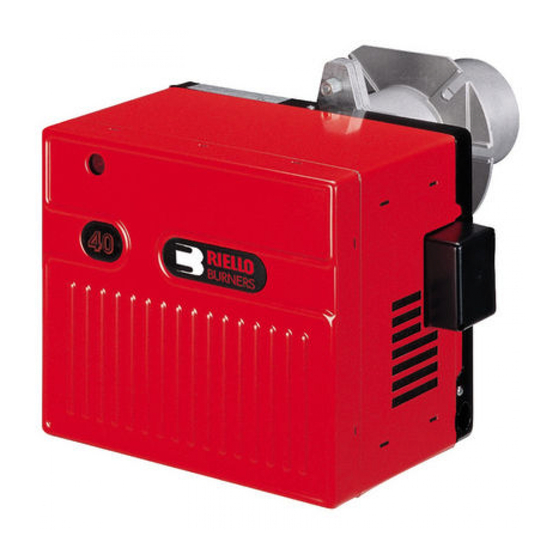
Installation & Operating Manual
Two stage operation forced draught natural gas/propane burner
The following pages contain information, descriptions and diagrams for the proper instal-
lation and wiring of the burner. Please read carefully before attempting final installation.
This manual is to remain with the final installation designation. It is the installer's responsibil-
ity to ensure that the burner installation and operation instructions mentioned in this manual
are followed and operated within local code authority limits.
CODE
3757313
MODEL
G900
TYPE
573T
2903245 (0)
Advertisement
Table of Contents

Related Manuals for Riello Two stage operation forced draught natural gas/propane burner


Summary of Contents for Riello Two stage operation forced draught natural gas/propane burner
- Page 1 Installation & Operating Manual Two stage operation forced draught natural gas/propane burner The following pages contain information, descriptions and diagrams for the proper instal- lation and wiring of the burner. Please read carefully before attempting final installation. This manual is to remain with the final installation designation. It is the installer’s responsibil- ity to ensure that the burner installation and operation instructions mentioned in this manual are followed and operated within local code authority limits.
-
Page 2: Table Of Contents
TABLE OF CONTENTS Installation instructions and owner's handbook ........... 2 General information . -
Page 3: Installation Instructions And Owner's Handbook
INSTALLATION INSTRUCTIONS AND OWNER'S HANDBOOK CAUTION: All gas burners MUST be installed by trained and licensed technicians. WARNING: Installation of this burner must conform with local codes requirements or, in the absence of local codes, with the Standard: National Fuel Gas code ANSI Z223.1-1984, and CAN/CGA B149.1 & 2 AND UL 795. If an external electrical source is utilized, the conversion burner, when installed, must be electrically grounded in accordance with local codes or, in the absence of local codes, with the national Electrical Code, ANSI/NFPA No. -
Page 4: General Information
" NPT plugged tapping must be installed immediately upstream of the burner gas train supply connec- tion and must be accessible for a test gauge. d) If required by local codes, provide gas vent lines at the gas regulators and valve (Riello gas trains are equipped with vent limiting orifices). -
Page 5: Installation Data
SERIAL NUMBER IDENTIFICATION Your Riello burner may have been manufactured in more than one location and therefore there are two possible serial number identification. The Riello 9 character serial number, example,... -
Page 6: Burner Dimensions
BURNER DIMENSIONS D7334 6 17 /3 2 ”-166 mm 8 1 / 4 ” - 210 mm 9 1 / 4 ” - 235 mm D7351 Model 900 inches NOTE: Actual available insertion length must be measured from tip of end cone to face of mounting gasket. ELECTRODE AND FLAME PROBE ADJUSTMENTS / "... -
Page 7: Typical Gas Train Layout
TYPICAL GAS TRAIN LAYOUT This gas train scope of supply meets the minimum controls requirements according to CGA and AGA regulations. Any additional requirements needed to meet local codes are the responsibility of others. FIELD SUPPLIED RIELLO SUPPLIED SEE GAS SUPPLY RANGE Ø... -
Page 8: Installing The Burner
INSTALLING THE BURNER A) Burner Chassis B) Combustion Head Assembly 1) Locking Nut 2) Mounting Plate surface 3) Insulation Gasket Separate the combustion head of the burner from the chas- sis (A) by removing the locknut (1). Install the combustion head into the boiler. -
Page 9: Installation Of Sediment Trap & Burner Supply
INSTALLATION OF SEDIMENT TRAP AND BURNER SUPPLY Gas piping to the burner must be -inch minimum. Install only a full-ported shutoff valve. The valve must be lo- cated outside the appliance jacket, and the pressure gauge port must be accessible. PRESSURE TEST-OVER PSIG. -
Page 10: Wiring Diagram
WIRING DIAGRAM R MG... 15 16 17 0 7 8 4 5 10 11 Wiring legend - Capacitor MV - Fuse 6.25A CN... - Connectors - Motor - Air pressure switch D7604 - Valve source interlock - Remote lock-out signal - Servomotor - Ionization probe - Ignition transformer... -
Page 11: Burner Head Setting
COMBUSTION HEAD SETTING To set combustion head, loosen the Allen screw (A) and move the elbow (B) so that the rear edge of the air tube (C) coincides with the set point number. Retighten the Allen screw (A). Make sure you are using the correct table for either Natural gas or Propane gas. -
Page 12: Preliminary Burner Adjustment
PRELIMINARY BURNER ADJUSTMENTS STANDBY WAITING FOR CALL FOR HEAT DO NOT ADJUST THIS SETTING FOR ANY REASON!!! The ST0 lever is set at the factory and corresponds to the air gate shut position of zero on the. D7342 STAGE (LOW FIRE) AIR DAMPER SETTING The ST1 lever controls the first stage position of the air damper and must be set at a higher degree setting than the ST0 Lever. -
Page 13: Combustion Chamber Size
COMBUSTION CHAMBER SIZE COMBUSTION CHAMBER SIZE Recommended Minimum Sizes KBtu/h NOTES: 1) Sizes shown above are for cylindrical or wet base boilers, or air cooled heat exchangers. 2) To size the chamber in applications other than wet base boilers, you must calculate area in square inches of the combustion zone required to give you a grate area or floor area to match the BTU inputs according to local authority. -
Page 14: Start-Up Cycle Diagnostics
START-UP CYCLE DIAGNOSTICS During start-up, indication is according to the followin table: COLOUR CODE TABLE Sequences Colour code Pre-purging Ignition phase Operation, flame ok Operating with weak flame signal. Electrical supply lower than ~ 170V Lock-out Extraneous light Index: Yellow Green RESETTING THE CONTROL BOX AND USING DIAGNOSTICS The control box features a diagnostics function through which any causes of malfunctioning are easily identified... -
Page 15: Software Diagnostics
SOFTWARE DIAGNOSTICS Reports the life of the burner by means of an optical link with the PC, indicating hours of operation, number and type of lock-outs, serial number of control box etc ... To view diagnostics, proceed as follows: Hold the button down for more than 3 seconds once the red LED (burner lock-out) remains steadily lit. A yellow light pulses to tell you the operation is done. -
Page 16: Problem Solving Guide
For any maintenance or repairs over and above those listed, contact your service technician or gas company. THERE ARE NO OWNER SERVICEABLE PARTS INSIDE THE BURNER COVER. Once a year, you should have the burner checked as indicated below, by your local authorized Riello dealer. 1) Check burner distributor head and mixing plates. Clean if necessary. -
Page 17: Spare Parts
SPARE PARTS 3245... -
Page 18: Spare Parts List
SPARE PARTS LIST CODE DESCRIPTION CODE DESCRIPTION 3007521 Burner back cover 3950471 Short combustion head (280T1) 3020227 Air pressure switch 3006697 Drawer assembly elbow 3005845 Burner motor 3006706 Electrode assembly 3007288 Air switch tube and connector 3003409 Electrode & ionization clamp 3007294 Air plate cover 3020209... -
Page 19: Burner Start-Up Form
35 Pond Park Rd. 2165 Meadowpine Blvd. Hingham, MA 02043 Mississauga,On L5H 3R2 Phone: 781-749-8292 Phone: 905-542-0303 Toll Free: 800-992-7637 Toll Free: 800-387-3898 Fax: 781-740-2069 Fax: 905-542-1525 BURNER START- UP FORM * Burner S/N. or Model: Appliance: Installer name: Company: Installation date: Address: Phone:... - Page 20 35 Pond Park Road 2165 Meadowpine Blvd Hingham, MA 02043 Mississauga, ON L5N 6H6 Phone 781-749-8292 Phone 905-542-0303 Toll Free 800-992-7637 Toll Free 800-387-3898 Fax 781-740-2069 Fax 905-542-1525 www.riellousa.com www.riellocanada.com Technical Support Hotline 1-800-4-RIELLO 1-800-474-3556...
Need help?
Do you have a question about the Two stage operation forced draught natural gas/propane burner and is the answer not in the manual?
Questions and answers