Table of Contents
Advertisement
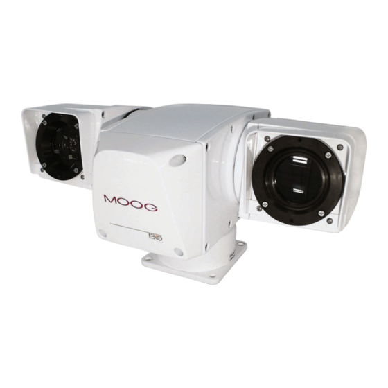
EXO GeminEye
HD Camera System QPT-LT Positioner
© 2013, Moog Inc. All Rights Reserved
Moog Inc.
Sensor and Surveillance Systems
3650 Woodhead Drive Northbrook, IL. USA 60062
+1.847.498.0700 Fax: +1.847.498.1258 www.moogS3.com
Installation and Operation Instructions
Before attempting to connect or operate this product, please
read these instructions completely.
MN00178
Advertisement
Table of Contents

Subscribe to Our Youtube Channel
Related Manuals for Moog EXO GeminEye

Summary of Contents for Moog EXO GeminEye
- Page 1 Before attempting to connect or operate this product, please read these instructions completely. EXO GeminEye HD Camera System QPT-LT Positioner Moog Inc. Sensor and Surveillance Systems 3650 Woodhead Drive Northbrook, IL. USA 60062 MN00178 © 2013, Moog Inc. All Rights Reserved +1.847.498.0700 Fax: +1.847.498.1258 www.moogS3.com...
-
Page 2: Table Of Contents
OPTO POSITION DETECTORS………………………………………………………………............8 DRIVE SYSTEM………………………………………………………………………………………........8 COMMUNICATIONS & CONTROL BOARD………………………………………………………...........8 SECTION IV TEST SOFTWARE..................................9 SOFTWARE SETUP......................................9 Moog Configuration Tool…………………………………………………………………………….........9 Using the Moog EXO Web Application................................12 Application……………………………………………………………………......……………......12 System Status.......................................13 Configuration.........................................14 Configuration / Date Time………………………………………………………………………………………………..14 Configuration Network……………………………………………………................15 Configuration / Network / DHCP..............................15 Configuration / Network / Host Name Configuration-NPT........................15 Configuration / Network / HTTP...............................15... -
Page 3: Section I
In models with both a visible and thermal camera, either channel can be used to operate and move the GeminEye. GeminEye will respond to Moog commands as outlined in the "PTL-11 Protocol"... -
Page 4: Specifications
Specifications PAN & TILT TInput Voltage 10 to 30 VDC Power Requirements Positioner w/Visible camera requires 60W during initialization or at start of move,30W during continuous motion, 11W at idle. If heaters are activated, an additional 72W is required. The FLIR Tau camera used in thermal imager models requires an additional 1.2W (approximate). -
Page 5: Accessories
Check the box contents for (1) Integrated Camera System, (1) mating connector, (1) test cable, (1) basic test software/manuals CD00556, and (1) system schematic. If any of the above components are missing, please contact Moog immediately, and please have your sales order number available. Claims for missing components must be filed within a reasonable time period from receipt. - Page 6 The tilt soft (software settable) limit is factory set at ±90 degrees. They can be adjusted to values less than the ±90 degree range. There is no pan soft limit in continuous mode, but there are user adjustable soft limits in the non-continuous rotation mode, when using the Moog PTZ controller. Refer to MN00307.
-
Page 7: Installation Procedures - Electrical
INSTALLATION PROCEDURES – ELECTRICAL: General Comments The interface cable between the computer and integrated camera system is important to the reliable operation of any motorized instrument positioning system. Selection of the type of cable, the size (AWG), the number of conductors required, grounding techniques, special consideration for wiring to the devices mounted on the pan/tilt unit, plug connections and the pan/tilt options are the topics covered in this Section. -
Page 8: Theory Of Operation
COMMUNICATIONS & CONTROL BOARD All communication to the EXO GeminEye model is through a Moog Video encoder, which is an IP connection only. There is one video encoder for each camera module, and either can provide motion control of the positioner. -
Page 9: Test Software
Permits batch firmware upgrade of all common EXO devices Note: Silverlight is a free plug in and is required to interface with the Moog EXO Web brower. Once your device is installed on your network and powered up, launch MDT from any computer on the network and the following window will be displayed: The MDT supports 2 ways to discover a device. - Page 10 The MCT will display as many devices as it discovers on the network If no DHCP server was able to assign an IP address to a Moog EXO Camera, it will appear in the MCT device list with an APIPA address (169.254.*.*). If a Moog Camera displays an APIPA address it must be configured with a valid IP address before it can be remotely configured by selection the "Assign IP address"...
- Page 11 To assign IP Address, update firmware, or configure Moog web interface, right click on highlighted serial number / Mac Address. Assign IP address(es) Once the IP information is set, the Silverlight web application served by the EXO Camera can be launched from the MDT or directly in your web browser by typing the device’s IP address in the address bar.
-
Page 12: Using The Moog Exo Web Application
Using the Moog EXO Web Application Application When entering the Web Application, the following window will be displayed. You will be asked a username and password. The default User name and Password is 'admin'. (To reset the user name and password see I Configurations I User Accounts) -
Page 13: System Status
System Status Status Window System Status - 2.1.0 Configuration - 2.2.0 Maintenance - 3.0.0 Live Viewer - 4.0.0 Recording - 5.0.0 Main Menu Tabs Upon successfully logging into the web interface, a welcome screen will be displayed. The welcome screen shows general devices health status as well as firmware version and system uptime. -
Page 14: Configuration
Configuration Under the Configuration section, select the System tab to perform the following operations: • View product model information, current firmware version and serial number. • Specify a custom name; this name can be used by third-party software to display a selected name for the device. Configuration / Date Time Under the Configuration section, select the Date Time tab to perform the following operations: •... -
Page 15: Configuration Network
Configuration Network Configuration / Network / DHCP Under the Configuration section, select the Network tab to perform the following operations: • Set the encoder’s IP parameters; DHCP or static IP information. • Configure an NTP server to allow the device to automatically update its internal clock using an NTP server. Configuration / Network / Host Name Configuration-NPT NPT Server- use when desiring to have local network time as default, to do so you must……. -
Page 16: Configuration / Network / Api- Boujour
Configuration / Network / API- Boujour NOTE: To control the EXO Camera system with a VMS software system, you must enable the required Network APIs. Enable PSIA or GENETEC API depending on which VMS platform you intend to use with the device. Disabling any unrequired APIs will accelerate boot time. Milestone VMS will link through the PSIA API. •... -
Page 17: Configuration / Video In / Video Input
VBR aggressiveness however is unique to Moog EXO Cameras and proposes various levels (disabled to aggressive) of motion triggered rate control. The more aggressive the setting, the more variation motion will have on the rate control. -
Page 18: Configuration / Video In / Video Compression
Configuration / Video In / Video Compression Set Quantization (QP) level to desired rate. The higher the number the greater the compression. (16 very low, 51 very high) Frame Rate - Allows you to specify the frame rate to be used by the codec. Rate Control - Allows you to choose between Variable Bit Rate and Constant Bit Rate. -
Page 19: Configuration / Video In / Text Overlay
Configuration / Video In / Text Overlay To insert a text overlay: • There are (2) available strings (Text blocks). Select string. • Select string Size. • For string position click mouse inside string position box. – Text bar will appear on video image. –... -
Page 20: Configuration / Video In / Motion Detection
Configuration / Video In / Motion Detection Select from 1 of 4 available regions: • With mouse click on region position box. • Bring mouse pointer to view window and drag box around area for motion detection. • Select desired Frame Count, Sensitivity and Thresholds. •... -
Page 21: Configuration / Audio Out
Configuration / Audio Out Under the Configuration section, select the Audio Out tab to perform the following operations: • Configure audio output parameters. • Configure a point to point audio connection for receiving a persistent audio stream from a network endpoint. MN00178 1359... -
Page 22: Configuration / User Accounts
Configuration / User Accounts Under the Configuration section, select the User Accounts tab to perform the following operations: • Select the web interface’s authentication method. A dual passphrase is made available for additional security. • Manage user accounts which have access to the device. User Roles: Administrator: All is available... -
Page 23: Maintenance
Click on the Maintenance tab. Click on the Update button. You will be asked for the firmware update file; please select the .iof file which was provided by Moog. You will see the following messages indicating the status of the update: •... -
Page 24: Live Viewer
Live Viewer Use Live View for: • Live Camera View • Start and Stop Recording • Pan / Tilt and Camera Control • Setting Presets • Adjust View Scale To enable live you must activate by pressing the “Play” button. Play Button To adjust viewing scale for 1024 x 768 monitor, press scale view MN00178... -
Page 25: Live Viewer Pan / Tilt And Presets
Live Viewer Pan / Tilt and Presets Pan / Tilt Controls Lens Controls Preset Controls • Pan Tilt Control; To operate Press Arrow in desired direction of movement. • Use Pan / Tilt speed slider controls to vary Pan / Tilt speed control, to increase speed, slide control knob to (?) •... -
Page 26: Performing Batch Firmware Update
Performing Batch Firmware Update This section describes how to perform a batch update of multiple Moog EXO Camera devices to newer firmware versions from the MCT. The batch firmware update works by starting a firmware update session. Only one session at time is allowed and only 20 devices can be selected by session. - Page 27 To start a firmware update session, choose the “.iof” file corresponding to the new firmware by clicking to the “Select File …” button. Once selected, click to the “Start” button. Once started, the “Firmware Update Session” window shows the progress of the firmware update. This window can be closed at any moment without losing the current session.
-
Page 28: Point To Point Connections
Point-to-point connections between an Moog EXO Camera and an Decoder can be configured using the device’s web application. In the Moog EXO web application, in the Configuration section, goes to the Video In tab. Scroll down all the way to the bottom of the configuration page. The last 3 sections are named Point to Point 1, 2 and 3.
Need help?
Do you have a question about the EXO GeminEye and is the answer not in the manual?
Questions and answers