
Subscribe to Our Youtube Channel
Related Manuals for Robur Line MC Series


Summary of Contents for Robur Line MC Series
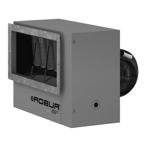
- Page 1 Installation, use and maintenance manual Heaters Line M C Series Gas fired unit heaters with centrifugal fan for heating medium-large areas Natural gas/LPG fired...
- Page 2 EDITION: 04/2007 Code: D-LBR447 This manual has been prepared and printed by Robur S.p.A.; whole or partial reproduction of this manual is prohibited. The original is filed on the premises of Robur S.p.A. Any use of this manual other than for personal consultation must be previously authorised by Robur S.p.A.
- Page 3 Preface INTRODUCTION This manual is intended for those who must install and use the Robur M C series warm air heaters. It is directed to the hydraulic system installation technicians who must install the heater, the electrical system installation technicians who must connect the heater to the main power supply and to the end users who must verify its normal operation.
- Page 4 M C Series – Warm air heaters – Installation, Operation and Maintenance Manual Meaning of icons The icons contained in the margin of the manual have the following meanings. Danger signal Warning Notes Start of operating procedure Reference to another part of the manual or to another manual/booklet Table 1 –...
-
Page 5: Table Of Contents
Index of contents INDEX OF CONTENTS SECTION 1: OVERVIEW & TECHNICAL CHARACTERISTICS ........7 1.1 GENERAL ADVICE..........................7 1.2 NOTES ON OPERATION OF THE APPLIANCE................9 1.3 MANUFACTURING CHARACTERISTICS ..................10 CONTROL AND SAFETY COMPONENTS ................10 1.4 TECHNICAL DATA .......................... 11 1.5 DIMENSIONS OF M C SERIES HEATERS .................. - Page 6 M C Series – Warm air heaters – Installation, Operation and Maintenance Manual MIXING CHAMBER ........................45 FILTER HOLDER........................45 AIR FILTER ..........................46 AIR FLOW ADJUSTMENT DAMPERS..................46 ANTI-VIBRATION JOINTS......................47 LOWER SUPPORT BEAMS ...................... 47 SUPPORT BRACKETS ......................47 Ed.
-
Page 7: Section 1: Overview & Technical Characteristics
Professionally qualified personnel means personnel that have specific technical expertise in the sector of heating plant components for civil use. In any case the user may obtain all necessary information by contacting ROBUR S.p.A. Customer Service Department (tel. 0039 035 888111). - Page 8 M C Series – Warm air heaters – Installation, Operation and Maintenance Manual the heater is supplied with fuel type for which it is set up for; the fuel supply pressure is within the values given on the data plate; the fuel supply plant is sized for the flow required by the heater and that it is equipped with all of the safety and control devices prescribed by current regulations.
-
Page 9: Notes On Operation Of The Appliance
Overview and general characteristics 1.2 NOTES ON OPERATION OF THE APPLIANCE The M C series warm air heater is an independent heating appliance with a sealed circuit, forced draught type. It has been designed to be installed inside the room to be heated and warm air is distributed through a connected air duct. -
Page 10: Manufacturing Characteristics
AISI 409 stainless steel, manufactured with non-welded seams heat exchanger, patented by ROBUR, in aluminium alloy with high heat exchange capacity with horizontal finns (air side) and vertical finns (flue side) self-supporting structure in sheet stainless steel painted with RAL 2008 orange... -
Page 11: Technical Data
Overview and general characteristics 1.4 TECHNICAL DATA MODEL U.M. M20 C M30 C M60 C APPLIANCE CATEGORY 2H3+ APPLIANCE TYPE C12 – C32 – B22 GAS TYPE Natural gas – LPG NOMINAL HEAT INPUT 20.6 34.8 72.5 NOMINAL HEATING OUTPUT 18.3 30.7 63.8... -
Page 12: Dimensions Of M C Series Heaters
M C Series – Warm air heaters – Installation, Operation and Maintenance Manual 1.5 DIMENSIONS OF M C SERIES HEATERS M20 C M30 C 1270 1010 1078 M60 C Ø EXT 113 Ø EXT 135 M20 C Ø EXT 113 Ø... -
Page 13: Section 2: User
User SECTION 2: USER In this section you will find all the indications necessary for operating the M C series heaters correctly. 2.1 HOW TO SWITCH THE HEATER ON AND OFF Initial activation must be carried out by professionally qualified personnel. Before starting the heater, have professionally qualified personnel check that: •... -
Page 14: Switching Off
M C Series – Warm air heaters – Installation, Operation and Maintenance Manual If ignition has taken place as expected, set the thermostat to the desired temperature. If the burner is ignited after a prolonged period of inactivity or for the first time, it may be necessary to repeat the operation several times as a result of air in the pipes. -
Page 15: Section 3: Hydraulic System Installation Technician
Professionally qualified personnel means personnel that have specific technical expertise in the sector of heating plant components. If in doubt contact Robur S.p.A. on +39-035-888111. Incorrect or non-compliant installation may cause damage to persons, animals or things, for which the manufacturer cannot be held responsible. - Page 16 M C Series – Warm air heaters – Installation, Operation and Maintenance Manual Check that an adequate gas supply and distribution network exists. Specifically, if the appliance runs on: Natural gas the gas mains pressure must be 20 mbar (204 mm H O) with a tolerance from 17 mbar to 25 mbar;...
-
Page 17: Sizing Of Combustion Air And Flue Pipes
Hydraulic system installation technician MIN. 200 mm Figure 3 – Clearances 3.3 SIZING OF COMBUSTION AIR AND FLUE PIPES M C series warm air heaters are approved for installation in one of the following ways: type installation: expulsion of combustion products and intake of combustion air are wall-based, via separate (see Figure 4 on page 18) or coaxial (see Figure 5 on page 18 and Figure 6 on page 19) ducts. - Page 18 M C Series – Warm air heaters – Installation, Operation and Maintenance Manual C12 TYPE INSTALLATION WITH SEPARATE WALL DUCTS SEEN FROM ABOVE REF. CODE Q.TY DESCRIPTION O-TBO011 Flue pipe adaptor, Ø 110 mm O-TBO003 Ø 110 mm pipe, length = 0.5 m O-TBO005 Ø...
- Page 19 Hydraulic system installation technician M 60 C: C12 TYPE INSTALLATION WITH COAXIAL WALL DUCT SEEN FROM ABOVE REF. CODE Q.TY DESCRIPTION O-TBO011 Flue pipe adaptor, Ø 110 mm O-TPP004 Intake plug on flue pipes O-TBO003 Ø 110 mm pipe, length = 0.5 m O-SCR001 Wall-mounted coaxial flue pipe, Ø...
- Page 20 M C Series – Warm air heaters – Installation, Operation and Maintenance Manual B22 TYPE INSTALLATION WITH WALL-MOUNTED EXHAUST DUCT SEEN FROM ABOVE REF. CODE Q.TY DESCRIPTION O-TBO011 Flue pipe adaptor, Ø 110 mm O-TBO003 Ø 110 mm pipe, length = 0.5 m O-TBO005 Ø...
- Page 21 (for further information see “AIR CHANGES” on page 25). It is necessary to use ducts approved for the type of installation to be carried out. ROBUR S.p.A. can supply to order rigid pipes, coaxial ducts and approved terminals.
- Page 22 M C Series – Warm air heaters – Installation, Operation and Maintenance Manual mixing chamber Figure 11 – Flue pipe set-up if a mixing chamber is used If a mixing chamber is installed (available as an accessory – see ACCESSORIES on page 45), in order to prevent combustion gases coming into contact with the heated environment it is important to avoid positioning the flue pipe outlet within the clearance area indicated in Figure 12.
- Page 23 Hydraulic system installation technician AIR DIAPHRAGM FLUE DIAPHRAGM PRESSURE DROP ADMISSIBLE (PA) MODEL HEIGHT (MM) CODE HEIGHT (MM) CODE MAXIMUM MINIMUM M20 C ----- ----- ----- ----- ----- M30 C ----- ----- ----- ----- ----- M60 C ----- ----- ----- ----- ----- Table 5 –...
-
Page 24: Example Of Calculation
The total pressure drop of the system of pipes (7.02 Pa) is LOWER than the maximum admissible pressure drop (25 Pa). Therefore the installation is PERMITTED. If the total length of the system of pipes is over 16 metres, contact Robur Pre-Sales Service on 035-888111. -
Page 25: Air Changes
Hydraulic system installation technician Insert the flue diaphragm between the flue outlet flange and the flue fan flange, so that the holes in the diaphragm are turned downwards. Line up the holes of the diaphragm with the lower holes. Retighten the upper and lower screws that fix the flue fan. Reposition the cover and retighten the fixing screw. -
Page 26: Wall Installation With Support Bracket
Table 8 – Pressure drops of aeration components 3.6 WALL INSTALLATION WITH SUPPORT BRACKET For the fitting of the Robur M C series heaters, an easy-to-fit support bracket is supplied (see ACCESSORIES on page 45). If this accessory is not used, refer to Figure 16 which indicates the minimum dimensions of the bracket for standard installations (without mixing chamber). -
Page 27: Section 4: Electrical System Installation Technician
Electrical system installation technician SECTION 4: ELECTRICAL SYSTEM INSTALLATION TECHNICIAN In this section you will find all the indications necessary for connecting the MC series heaters electrically. 4.1 HOW TO CONNECT THE HEATER TO THE POWER SUPPLY You will need: the heater installed. Electrical connections must be made by professionally qualified personnel. -
Page 28: How To Connect The Thermostat To The Heater
M C Series – Warm air heaters – Installation, Operation and Maintenance Manual Connect the heater to the power supply and switch it on. Close the gas valve and check that after a few seconds the arrest warning light A comes on (see Figure 2). -
Page 29: How To Make The Electrical Connection For Summer Operation
Electrical system installation technician 4.4 HOW TO MAKE THE ELECTRICAL CONNECTION FOR SUMMER OPERATION To change from winter to summer operation (fan operation only), follow the instructions below. You will need: the heater connected to the power and gas supply. Close the gas valve and disconnect the appliance from the power supply. -
Page 30: Assembly Wiring Diagram
M C Series – Warm air heaters – Installation, Operation and Maintenance Manual 4.5 ASSEMBLY WIRING DIAGRAM Figure 18 – Assembly wiring diagram for M C series appliances (see key to Figure 19) Ed. 04/2007... -
Page 31: Operation Wiring Diagram
Electrical system installation technician 4.6 OPERATION WIRING DIAGRAM 1 2 3 4 5 6 7 13 14 15 16 17 18 19 J6 JT1 J5 JT2 230V-50HZ RP8 RP7 CM fan condenser gas electrovalve flue fan condenser soft opening modulator arrest warning light (for M 60 C model) fan motor... -
Page 32: Wiring Diagram For Connection Of Several Heaters
M C Series – Warm air heaters – Installation, Operation and Maintenance Manual 4.8 WIRING DIAGRAM FOR CONNECTION OF SEVERAL HEATERS HEATER HEATER HEATER PROGRAMMABLE TIMER AMBIENT THERMOSTATS RL1-2-3 = PROGRAMMED CONTROL RELAY 230 V - 50 Hz Figure 21 - Wiring diagram for several heaters with a single programmable timer and several ambient thermostats = PROGRAMMABLE TIMER = AMBIENT THERMOSTATS RL1-2-3 = PROGRAMMED... - Page 33 Electrical system installation technician HEATER HEATER HEATER = PROGRAMMABLE TIMER = AMBIENT THERMOSTATS RL1-2-3 = PROGRAMMED CONTROL RELAY 230 V - 50 Hz Figure 23 - Wiring diagram for several heaters with a single programmable timer and a single ambient thermostat (solution with a single relay) Ed.
- Page 34 M C Series – Warm air heaters – Installation, Operation and Maintenance Manual Ed. 04/2007...
-
Page 35: Section 5: Technical Assistance And Maintenance
Technical assistance and maintenance SECTION 5: TECHNICAL ASSISTANCE AND MAINTENANCE In this section you will find all the indications necessary for service technicians to carry out regulation of the gas valve and change of gas type, as well as some indications regarding maintenance. -
Page 36: Operation With L.p.g. Gas
M C Series – Warm air heaters – Installation, Operation and Maintenance Manual OPERATION WITH L.P.G. GAS You will need: the heater installed and connected to the power and gas supply. Check that the adjustment screw, B, is tightened (see Figure 24 or Figure 25). If it is not, tighten it completely. - Page 37 Technical assistance and maintenance After regulation has been completed, the adjustment screw of the gas valve must be sealed. A) Soft opening adjustment B) Nut for regulation of pressure at the burner C) Adjustment screw protection D) Electrical connector SMD soft opening coil E) Connector for measurement of intake gas pressure Connector for measurement of outlet gas pressure G) Electrical power connectors...
-
Page 38: How To Change Gas Type
M C Series – Warm air heaters – Installation, Operation and Maintenance Manual 5.2 HOW TO CHANGE GAS TYPE You will need: the heater connected to the power and gas supply. Change of gas type must be carried out by professionally qualified personnel. Incorrect or careless assembly of the gas circuit may cause dangerous gas leaks from all of the circuit and in particular from zones that are tampered with. -
Page 39: Maintenance
Technical assistance and maintenance 5.3 MAINTENANCE Careful maintenance is always at the basis of economy and safety. Maintenance for heating units must be carried out, preferably at the beginning of winter, by qualified service engineers. For correct, prolonged operation, general cleaning of the appliance is recommended at least once a year (giving particular attention to the heat exchangers and fan grilles), as well as combustion tests as applicable under specific regulations. -
Page 40: Case No. 2: The Unit Locks Out During Operation
M C Series – Warm air heaters – Installation, Operation and Maintenance Manual F) Failure in the flame control unit or in its electrical connections. G) Failure in the gas valve or in its electrical connections. H) Soft opening pressure too low. I) Check that the unit has a good earth. -
Page 41: Case No. 6: The Exhaust Fan Starts But The Unit Does Not Ignite
Technical assistance and maintenance CASE NO. 6: THE EXHAUST FAN STARTS BUT THE UNIT DOES NOT IGNITE. W) Intake and/or exhaust duct are obstructed or too long. X) The electrical or pneumatic connections of the pressure switch are faulty Y) The flame control unit does not start the cycle: replace the internal fuse of the flame control unit or the control unit itself. - Page 42 M C Series – Warm air heaters – Installation, Operation and Maintenance Manual TROUBLESHOOTING FLOWCHART FOR UNIT HEATERS The heater does not Main switch start neither for heating nor for ventilation Check the fuse. Is Replace the Consult your it burnt-out? fuse installer Open the gas supply.
- Page 43 Technical assistance and maintenance continued Does the flue fan Replace the anti-welding stop and go? device of pressure switch Replace the Replace the ignition electrode fuse Check the ignition electrode and Does the electrode start related cable. Is the electrode Is the control unit Replace the sparking in the burner...
- Page 44 M C Series – Warm air heaters – Installation, Operation and Maintenance Manual Ed. 04/2007...
-
Page 45: Section 6: Accessories
Accessories SECTION 6: ACCESSORIES This section contains a list of accessories available for the installation and use of the M C series heaters. For pressure drops associated with the accessories, refer to Table 8 on page 26. MIXING CHAMBER The mixing chamber allows the ventilation air intake to be connected to the outside. The chamber is ready to fit on the rear part of the heater and allows it to be connected to both rear and lower air intake ducts. -
Page 46: Air Filter
M C Series – Warm air heaters – Installation, Operation and Maintenance Manual AIR FILTER Class G3 air filter (EN 779) to be fitted in the special filter holder. For M 60 series heaters, two filters must be used for each intake side (rear or lower). AIR FILTER 400 X 500 O-FLT013... -
Page 47: Anti-Vibration Joints
Accessories ANTI-VIBRATION JOINTS These make it possible to connect the rear and front combustion air intake ducts to the mixing chamber, preventing potential vibrations. ANTI-VIBRATION JOINT 400 X 500 O-GTV018 FOR M 20 C ANTI-VIBRATION JOINT 500 X 500 O-GTV019 FOR M 30 C ANTI-VIBRATION JOINT 500 X 1,000... - Page 48 Muoverci dinamicamente, nella ricerca, sviluppo e diffusione di prodotti sicuri, ecologici, a basso consumo energetico, attraverso la consapevole responsabilità di tutti i collaboratori. La Mission Robur Robur Spa tecnologie avanzate per la climatizzazione Via Parigi 4/6 24040 Verdellino/Zingonia (Bg) Italy T +39 035 888111 F +39 035 884165 www.robur.it...
Need help?
Do you have a question about the Line MC Series and is the answer not in the manual?
Questions and answers