
Related Manuals for Robur Calorio M


Summary of Contents for Robur Calorio M
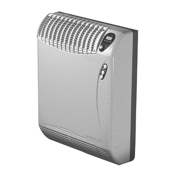
- Page 1 Installation, use and maintenance manual Calorio Serie Balanced flues gas heaters Natural gas / LPG fired...
- Page 2 Revision: C Code: D-LBR701 This instruction manual has been drawn up and printed by Robur S.p.A.; whole or partial reproduction of this manual is strictly prohibited. The original is filed at Robur S.p.A. Any use of this manual other than for personal reference must be authorized in advance by Robur S.p.A.
- Page 3 Introduction INTRODUCTION This manual is addressed to all installers and users of Robur Calorio M independent gas- fired heaters. In particular, this manual is intended for the gas engineer who will install the heater, the electrician who will connect it to the mains power supply and the end user who will control it during everyday operation.
- Page 4 Calorio M Line - Installation, use and maintenance manual Symbol meanings The symbols used in the manual have the following meanings. Danger Warning Note Start of operational procedure Reference to another part of the manual or to a different manual/booklet Table 1 –...
-
Page 5: Table Of Contents
1.2 BRIEF DESCRIPTION OF HEATER OPERATION ................9 1.3 CONSTRUCTION ..........................10 1.4 TECHNICAL DATA .......................... 11 1.5 DIMENSIONS OF CALORIO M HEATERS ..................12 SECTION 2 USER SECTION ..................13 2.1 BUTTON FUNCTIONS ........................13 2.2 KEY TO DISPLAY ICONS ....................... 14 2.3 OPERATION OF THE KNOB...................... - Page 6 Calorio M Line - Installation, use and maintenance manual NATURAL GAS OPERATION ......................34 LPG OPERATION ..........................35 5.4 SAFETY DEVICES........................... 37 5.5 MALFUNCTIONS ..........................38 CASE 1: THE UNIT LOCKS OUT DURING THE FIRST IGNITION PROCEDURE ..... 38 CASE 2: THE HEATER LOCKS OUT DURING NORMAL OPERATION ........38 CASE 3: FAILURE IN COMMUNICATION BETWEEN MAIN CIRCUIT BOARD AND USER INTERFACE (error Ncom).
-
Page 7: Section 1 Overview And Technical Characteristics
Table of contents SECTION 1 OVERVIEW AND TECHNICAL CHARACTERISTICS This section contains general instructions regarding the installation and use of Calorio M independent gas-fired heaters, and a brief summary of their operation, construction and technical data. 1.1 GENERAL WARNINGS This manual constitutes an integral and essential part of the product and must be delivered to the user together with the appliance. - Page 8 Calorio M Line - Installation, use and maintenance manual the sealing of the gas supply system, both internal and external. the gas flow rate setting is appropriate for the heater’s power rating. the gas supplied to the heater is of the type with which it is designed to operate.
-
Page 9: Brief Description Of Heater Operation
(see SECTION 2). The operating principle of the Calorio M heater is based on the convection of room air. The air is drawn up through the unit, where it is heated, and then discharged into the room through the outlet grille at the top. -
Page 10: Construction
Calorio M Line - Installation, use and maintenance manual 1.3 CONSTRUCTION Calorio M gas-fired heaters are supplied complete with: high-performance combustion chamber and tubular heat exchanger (patented) made from stainless steel; control board: controls burner ignition, flame detection and modulation functions;... -
Page 11: Technical Data
Table of contents 1.4 TECHNICAL DATA DESCRIPTION U.M. 42 M 52 M TYPE CATEGORY 2H3+ NOMINAL HEAT INPUT - MAX. 3.62 5.23 NOMINAL HEAT OUTPUT - MAX. 3.26 4.71 NOMINAL HEAT INPUT - MIN. 2.51 3.60 NOMINAL HEAT OUTPUT - MIN. 2.26 3.18 NOMINAL NO... -
Page 12: Dimensions Of Calorio M Heaters
Calorio M Line - Installation, use and maintenance manual 1.5 DIMENSIONS OF CALORIO M HEATERS Figure 1 – Dimensions of Calorio heaters... -
Page 13: Section 2 User Section
Table of contents SECTION 2 USER SECTION This section contains all the necessary information on how to operate the Calorio M gas- fired heater. Operation of the Calorio M heater is controlled from the digital display fitted as standard. The temperature shown on the display is the temperature of the air entering the heater (as read by the temperature sensor located near the lower intake grille). -
Page 14: Key To Display Icons
Calorio M Line - Installation, use and maintenance manual 2.2 KEY TO DISPLAY ICONS ICON DESCRIPTION MEANING THE HEATER IS OFF HAND MANUAL OPERATION CLOCK AUTOMATIC OPERATION PADLOCK THE CONTROLS LOCK IS ACTIVE WINTER MODE (COMFORT TEMPERATURE MAINTAINED) MOON WINTER MODE (ECONOMY TEMPERATURE MAINTAINED) -
Page 15: Turning On The Heater
Table of contents If there is a call for heat (measured temperature below the required temperature setting) the gas solenoid valve will open and the ignition electrode will start to spark. When a flame is detected, the control board will automatically stop the electrode sparking and will keep the heater in operation. -
Page 16: Turning Off The Heater
Economy, and Frost protection). For programming instructions, refer to the paragraph SETTING THE COMFORT/ECONOMY on page 17. 2.5 OPERATING MODE SELECTION The different operating modes of the Calorio M heater are described below. MANUAL OPERATION Press manual operation button B : the hand icon appears on the display. -
Page 17: Temporary Manual Operation
Table of contents TEMPORARY MANUAL OPERATION If the ambient temperature is changed (by turning and pressing the control knob) during “Automatic operation” (see relative paragraph), the operating mode will switch from Automatic to “Temporary Manual”. In this operating mode, the manually set ambient temperature (shown on the display) will be maintained until the next change in the automatic time schedule or until the user presses button B The display shows the fixed auto icon... -
Page 18: Frost Protection Temperature Setting
Calorio M Line - Installation, use and maintenance manual The “Comfort” setting is the temperature maintained by the heater during ON periods in automatic operation. The comfort temperature setting must be higher than the Economy temperature setting. Press button B MENU... -
Page 19: Display Backlight Function
Calorio M (in the lower part of the frame there is an access hole for the thermostat wire). For further... -
Page 20: Controls Lock Function
Calorio M Line - Installation, use and maintenance manual CONTROLS LOCK FUNCTION This function allows you to enable the controls lock (buttons and knob disabled) to prevent settings from being changed by unauthorized persons or by accidental operation of the buttons. -
Page 21: Section 3 Gas Engineer
Table of contents SECTION 3 GAS ENGINEER This section contains all the necessary information for the connection of the Calorio M heater to the gas supply. 3.1 GENERAL INSTRUCTIONS FOR INSTALLATION OF THE HEATER The heater must be installed in accordance with the manufacturer's instructions by professionally qualified personnel. -
Page 22: Flue And Combustion Air Intake
Calorio M Line - Installation, use and maintenance manual 3.2 FLUE AND COMBUSTION AIR INTAKE The flue and combustion air intake for Calorio M heaters can be achieved in any of the following ways: • With coaxial pipes with outlet through the installation wall (max. pipe length: 1 metre) (see Figure 3). -
Page 23: Installation Procedures
Table of contents 3.3 INSTALLATION PROCEDURES In accordance with the installation project, prepare the gas and electrical power supplies and make the holes for the flue and combustion air intake pipes. MOUNTING THE HEATER ON THE WALL Before unpacking the unit, check the condition of the external packaging for signs of damage;... - Page 24 Calorio M Line - Installation, use and maintenance manual Support bracket staffa di sostegno Adhesive seal guarnizione adesiva Air pipe tubo aria Figure 6 – Positioning the support bracket and drilling the holes for models 41, 42, 51 and 52 Position the support bracket and the 49 mm Ø...
- Page 25 Table of contents 35 mm Ø flue pipe Figure 8 – Positioning the flue pipe Figure 9 – Attachment to the support bracket 12. Locate slots B on the ends A of the support bracket and push the heater towards the wall so that it seats against the support bracket (see Figure 10).
-
Page 26: Connect The Heater To The Gas Supply
Calorio M Line - Installation, use and maintenance manual CONNECT THE HEATER TO THE GAS SUPPLY The connection to the gas supply must be made using a rigid metal pipe in copper or steel; alternatively a flexible stainless steel pipe conforming to UNI CIG 9891 may be used. - Page 27 Table of contents Figure 12 - Fixing the flue terminal...
-
Page 28: Section 4 Electrician
Calorio M Line - Installation, use and maintenance manual SECTION 4 ELECTRICIAN This section contains all the necessary information for the electrical connection of the Calorio M heater. Preconditions: the heater must be installed. The electrical connection of the heater must be carried out by professionally qualified personnel. -
Page 29: Wiring Diagram
Table of contents 4.1 WIRING DIAGRAM SCHNITTSTEL External enabling LEN-KARTE signal connection SCH - Electronic circuit board RP7 Ignition electrodes Gas valve RP8. Detector electrode Line Combustion air blower Neutral Room fan Manual reset limit thermostat Prelimit temperature sensor 2A fuse Ambient air temperature sensor Electrical connectors Figure 14 –... - Page 30 Calorio M Line - Installation, use and maintenance manual Internal terminal box Relay External enable Main switch Line Neutral Figura 15 Internal terminal box Relay External enable Main switch Line Neutral Figura 16...
-
Page 31: Section 5 Servicing And Maintenance
Table of contents SECTION 5 SERVICING AND MAINTENANCE This section contains the necessary information for service engineers to regulate the gas valve and change the gas type, along with indications for servicing the heater. 5.1 ACCESS TO THE ADVANCED SETTINGS MENU The heater's electronic control system provides a number of advanced settings and functions which can only be enabled by professionally qualified personnel. -
Page 32: Gas Type Conversion
Calorio M Line - Installation, use and maintenance manual 5.2 GAS TYPE CONVERSION This operation must only be carried out by professionally qualified personnel. Incorrect or careless assembly of the gas circuit can result in hazardous gas leaks in the circuit, especially in the areas directly affected. Use suitable sealants on all gas fittings. -
Page 33: Conversion From Lpg To Natural Gas
Table of contents Figure 17 – Detail of burner assembly and detail of the injector holder and calibrated injector CONVERSION FROM LPG TO NATURAL GAS Preconditions: the heater must be installed and connected to the electrical power supply and the gas supply. Disconnect the electrical power supply and shut-off the gas supply. -
Page 34: How To Regulate The Gas Valve
Regulation of the gas valve must be carried out by professionally qualified personnel. ROBUR S.p.A. has a network of Assistance Centres which can be contacted via your dealer or area agent, or by telephoning directly ROBUR S.p.A. Customer Assistance tel.+39 035/888111. -
Page 35: Lpg Operation
Table of contents 10. Save the new parameter settings by turning the knob to display parameter P002 and then pressing it to confirm. 11. Deactivate the "valve calibration" function by turning the knob and pressing it to set parameter P002 to "0": the heater will turn off. 12. - Page 36 Calorio M Line - Installation, use and maintenance manual Turn the knob to display the parameter P03 "gas pressure at maximum power calibration". Press the knob and increase the value displayed from 1 to 5 (this operation may be repeated a number of times), until the pressure gauge shows a reading of 25 mbar;...
-
Page 37: Safety Devices
Table of contents 5.4 SAFETY DEVICES If the electrical power supply is interrupted: the heater will turn off and close the gas valve. When electrical power is restored, the heater will automatically turn back on. In the event of a loss of gas supply or other problem causing the flame to be extinguished: the heater will automatically attempt to reignite the... -
Page 38: Malfunctions
Calorio M Line - Installation, use and maintenance manual 5.5 MALFUNCTIONS Before checking for faults, always check that: The electrical power supply is present. The gas supply is present The supply pressure at the burner is within the specified tolerance range. -
Page 39: Interface (Error Ncom)
Table of contents CASE 3: FAILURE IN COMMUNICATION BETWEEN MAIN CIRCUIT BOARD AND USER INTERFACE (error Ncom). Malfunction of the user interface or the main circuit board. Before removing the casing, DISCONNECT THE HEATER FROM THE POWER SUPPLY by turning off the isolator switch upstream of the heater or by removing the plug from the socket. -
Page 40: Cleaning And Maintenance
Assistance Centres (TAC) which can be contacted via your area agent, or by telephoning ROBUR S.p.A. directly (Tel.: +39 035/888111). Before telephoning Robur S.p.A. Technical Service, make sure you have the heater documentation to hand and if possible: the serial number and model of heater (which can be found on the data plate and in the warranty booklet), the gas type and a brief description of the type of installation. -
Page 41: Appendix Advanced Heater Adjustment And Control Functions
Table of contents APPENDIX ADVANCED HEATER ADJUSTMENT AND CONTROL FUNCTIONS The "transparent control parameters" are listed in the table below. Access to the "transparent control parameters" is restricted to professionally qualified personnel. DEFAULT FUNCTION PERMITTED SETTINGS USER LEVEL VALUE 0 = methane Gas type selection installer 1 = LPG... -
Page 42: Description Of Advanced Functions
Calorio M Line - Installation, use and maintenance manual DESCRIPTION OF ADVANCED FUNCTIONS P001 - Gas type selection Regulates the gas valve in accordance with the gas used (methane or LPG). P002 – Activation of the gas valve calibration procedure Allows activation of the gas valve calibration procedure at maximum and minimum operating pressure. -
Page 43: P010 - Service Parameters Access Code
Table of contents The burner will always operate at maximum power and cannot be modulated. When the contact on the terminal block is open, the burner will not start. P010 – Service parameters access code Allows access to advanced functions, the use of which is restricted to authorized Technical Assistance Centres. - Page 44 Robur is dedicated to dynamic progression in research, development and promotion of safe, environmentally-friendly, energy-efficiency products, through the commitment and caring of its employees and partners. Robur Mission Robur Spa advanced heating and cooling technologies Via Parigi 4/6 24040 Verdellino/Zingonia (Bg) Italy T +39 035 888111 F +39 035 4821334 www.robur.com...
Need help?
Do you have a question about the Calorio M and is the answer not in the manual?
Questions and answers