Graco GM3000 Instructions-Parts List Manual
Airless
Hide thumbs
Also See for GM3000:
- Instructions-parts list manual (45 pages) ,
- Instructions-parts list manual (44 pages) ,
- Instructions-parts list manual (44 pages)
Table of Contents
Advertisement
Parts
INSTRUCTIONS-PARTS LIST
This manual contains important
warnings and information.
READ AND KEEP FOR REFERENCE.
INSTRUCTIONS
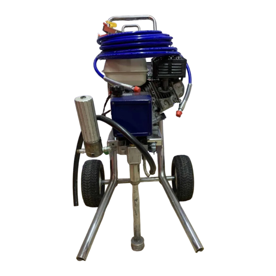
GM3000 Airless Paint Sprayer
3000 psi (210 bar, 21 MPa) Maximum Working Pressure
Model 231363, Series B
Basic Sprayer with Upright Cart
Model 231551
Same as 231363, with hose and gun, RACr X
HandTitet Tip Guard, and 517 size SwitchTipt
Model 231550, Series B
Basic Sprayer with Lo–Boy Cart
Model 231552
Same as 231550, with hose and gun, RACr X
HandTitet Tip Guard, and 517 size SwitchTipt
CAUTION
Always use a minimum hose length of 50 foot
(15 m) 1/4 inch ID or 50 foot (15 m) 3/8 inch ID. An
undersized hose may result in poor equipment
performance and damage to the clutch.
GRACO INC. P.O. BOX 1441 MINNEAPOLIS, MN 55440–1441
Model 231363 Shown
ECOPYRIGHT 1996, GRACO INC.
Graco Inc. is registered to I.S. EN ISO 9001
308620
Rev. K
06001B
Advertisement
Table of Contents

Related Manuals for Graco GM3000


Summary of Contents for Graco GM3000
- Page 1 (15 m) 1/4 inch ID or 50 foot (15 m) 3/8 inch ID. An undersized hose may result in poor equipment performance and damage to the clutch. 06001B Model 231363 Shown GRACO INC. P.O. BOX 1441 MINNEAPOLIS, MN 55440–1441 ECOPYRIGHT 1996, GRACO INC. Graco Inc. is registered to I.S. EN ISO 9001...
-
Page 2: Table Of Contents
D Use the equipment only for its intended purpose. If you are not sure, call your distributor. D Do not alter or modify this equipment. Use only genuine Graco parts. D Check equipment daily. Repair or replace worn or damaged parts immediately. -
Page 3: Warnings
WARNING INJECTION HAZARD Spray from the gun, leaks or ruptured components can inject fluid into your body and cause extremely serious injury, including the need for amputation. Fluid splashed in the eyes or on the skin can also cause serious injury. D Fluid injected into the skin may look like just a cut, but it is a serious injury. -
Page 4: Fire And Explosion Hazard
WARNING FIRE AND EXPLOSION HAZARD Improper grounding, poor ventilation, open flames or sparks can cause a hazardous condition and result in a fire or explosion and serious injury. D If there is any static sparking or you feel an electric shock while using this equipment, stop spray- ing immediately. -
Page 5: Component Identification And Function
Component Identification and Function 0015 0016 06001B Fig. 1 Pressure Control Switch ON/OFF, enables/disables clutch function Pressure Adjusting Knob Controls fluid outlet pressure Air Cleaner* Filters air entering the carburetor Fuel Tank* Holds 0.66 gallons (2.5 liters) of [(R+M)/2]; 86 octane gasoline Muffler* Reduces noise of internal combustion Spark Plug Cable*... -
Page 6: Setup
Setup 2. Fill packing nut/wetcup. Fill the packing nut/wet- CAUTION cup (A) 1/3 full with Graco Throat Seal Liquid (TSL), supplied. See Fig. 2. To avoid damaging the pressure control, which may result in poor equipment performance and component 3. Check the engine oil level. Refer to the Honda damage, follow these precautions. - Page 7 Setup 4. Be sure your system is properly grounded 8. Keep the sprayer upright and level during before operating it. Connect the sprayer to a true operation and whenever it is being moved. See the earth ground with the grounding wire and clamp CAUTION on page 10.
-
Page 8: Fueling
Fueling 2. Gasolines containing alcohol (gasohol). Do not WARNING use gasohol which contains methanol, if the gaso- hol does not contain cosolvents and corrosion FIRE AND EXPLOSION HAZARD inhibitors for methanol. Even if it does contain such Gasoline is extremely flammable and additives, do not use the gasohol if it contains explosive under certain conditions. -
Page 9: Startup
Startup Before You Start the Sprayer 4. Move the pressure control switch to OFF. 1. See Flushing on page 12 to determine if you 5. To start the engine: should flush the sprayer. a. Turn the pressure adjusting knob all the way counterclockwise to the lowest pressure set- 2. - Page 10 Startup 7. Prime the pump: h. Relieve pressure by opening the pressure drain valve. a. Place the suction tube in the bucket of paint, water, or solvent. Close the pressure drain valve. b. Open the pressure drain valve. WARNING c. Set engine speed to idle. INJECTION HAZARD d.
-
Page 11: Maintenance
Startup Loss of Prime to Pump CAUTION Introduction of air into the pump, either by changing fluids or due to a suction leak, may result in the loss of Operating the sprayer with the pump not primed can prime to the pump. If the pump loses prime, no fluid is lead to premature packing wear and/or damage to pumped. -
Page 12: Flushing
Pressure Relief Procedure 1. Engage the gun safety latch. WARNING 2. Turn the engine switch to OFF. 3. Move the pressure control ON/OFF switch to OFF. INJECTION HAZARD 4. Disengage the gun safety latch. Hold a metal part The system pressure must be manually of the gun firmly to a grounded metal pail. - Page 13 Flushing How to Flush WARNING CAUTION FIRE AND EXPLOSION HAZARD To reduce static sparking and splashing, always remove the spray tip from the When changing fluids, do not drain all of the first fluid gun, and hold a metal part of the gun from the suction tube before inserting the suction tube firmly to the side of a grounded metal pail when into the another fluid.
-
Page 14: Troubleshooting
Have the pressure control checked by an au- thorized Graco dealer. The clutch is worn, damaged, or incorrectly Replace the clutch. See page 25. positioned. - Page 15 PROBLEM CAUSE SOLUTION The pump output is low on The inlet screen (102) is clogged. Clean the screen. the upstroke the upstroke. A piston ball (121) is not seating. Service the piston ball–check. See page 31. The piston packings are worn or damaged. Replace the packings.
-
Page 16: Drive Housing, Connecting Rod, Crankshaft
Drive Housing, Connecting Rod, Crankshaft 6. Remove and inspect the crankshaft (8) and the WARNING connecting rod (10). INJECTION HAZARD To reduce the risk of serious injury, Installation whenever you are instructed to relieve pressure, follow the Pressure Relief 7. Lubricate the inside of the drive housing bronze Procedure on page 12. - Page 17 Drive Housing, Connecting Rod, Crankshaft REF A Torque to 100 in–lb (11 N.m) Quantity of three Quantity of one Lubricate with SAE non-detergent oil 05833B Fig. 5 Brush G-n lubricant and recoat with bearing grease Pack with bearing grease (0.22 pint) Fig.
-
Page 18: Pressure Control
Pressure Control 7. Loosely install the screws (24) and then torque WARNING them to 21 in–lb (2.4 N.m). INJECTION HAZARD 8. Install the front cover (9). Connect the harness (A) To reduce the risk of serious injury, to the control module leads (B). whenever you are instructed to relieve pressure, follow the Pressure Relief Procedure on page 12. -
Page 19: Control Module
Control Module 303 304 63 WARNING INJECTION HAZARD To reduce the risk of serious injury, whenever you are instructed to relieve pressure, follow the Pressure Relief Procedure on page 12. NOTE: See Fig. 8 for this procedure. 1. Relieve pressure. 2. -
Page 20: Pressure Transducer
Pressure Transducer WARNING INJECTION HAZARD To reduce the risk of serious injury, whenever you are instructed to relieve pressure, follow the Pressure Relief Procedure on page 12. NOTE: See Fig. 9 for this procedure. 1. Remove the displacement pump. See page 31. 2. -
Page 21: Suction Hose
Suction Hose Models 231550 and 231552 Lubricate WARNING INJECTION HAZARD To reduce the risk of serious injury, whenever you are instructed to relieve pressure, follow the Pressure Relief Procedure on page 12. 1. Separate the drain hose (31) from the suction hose (32). -
Page 22: Drain Valve
Drain Valve Repair WARNING 1. Unscrew the spring retainer (43h) from the valve body. Remove the spring, washers and stem/ball. INJECTION HAZARD Clean any debris from the ball or seat area. To reduce the risk of serious injury, whenever you are instructed to relieve 2. -
Page 23: Pinion, Clutch, Clamp, Field, & Engine
Pinion, Clutch, Clamp, Field, & Engine If servicing clutch components only, see page 25. 8. Reassemble to drive housing. If no service is needed for internal parts of pinion CAUTION housing, remove drive assembly (drive and pinion housing) from clutch housing. See page 25. Do not lose the thrust ball (2d). -
Page 24: Pinion Housing
Pinion Housing Lubricate inner and Detail A outer diameters Lubricate teeth Directional arrow on roller clutch must face the small bearing (2n) Lubricate exterior Back of pinion housing 1.53 Press fit small bearing (2n) and clutch roller (s) here 06005 Fig. -
Page 25: Clutch
Clutch 3. Pull the drive assembly (D) away from the clutch WARNING housing (1). INJECTION HAZARD 4. The armature (51b) will move with the drive as- To reduce the risk of serious injury, sembly. Remove the armature from the pinion hub whenever you are instructed to relieve (2h). -
Page 26: Engine
The engine for this sprayer is manufactured by Honda to a special Graco specification. 1. Working under the mounting plate (A), remove the two lock nuts (78) and then pull the screws (77) out of the base of the engine. -
Page 27: Field & Wiring Harness
Field & Wiring Harness NOTE: Refer to Fig. 18. 1. Back out the four setscrews (58) holding the field (53) to the clutch housing (1) approximately 3 turns. 2. Pull out the field. The field fits closely to the clutch housing and must be removed carefully to prevent jamming. -
Page 28: Reassembly
Reassembly To check the dimension, place a rigid, straight CAUTION steel bar (B) across the face of the clutch housing (1). Use an accurate measuring device to measure The sprayer will be out of balance when only the the distance between the bar and the face of the engine and clutch housing are installed. - Page 29 Reassembly The face of the housing. CAUTION 1.41 ".010 inch (35.8 ".25 mm). The sprayer will be out of balance when only the Torque the screws to engine and clutch housing are installed. Support the 120 in–lb (14 N.m). rear of the cart to prevent the sprayer from falling over.
- Page 30 Reassembly 6. Be sure the face of the rotor (51a) and the clamp 8. Clean the face of the armature (51b). With the flat (55) are free of all burrs. Install the rotor, lock- side of the armature facing the rotor (51a), slide washers (16) and capscrews (57).
-
Page 31: Displacement Pump Repair
Displacement Pump Repair Removing the pump (See Fig. 24.) WARNING 1. Flush the pump, if possible. Relieve pressure. Stop the pump with the piston rod (107) in its lowest INJECTION HAZARD position, if possible. To reduce the risk of serious injury, whenever you are instructed to relieve pressure, follow the Pressure Relief 2. - Page 32 4. Tighten the packing nut (102) just enough to stop leakage, but no tighter. Fill the packing nut/wet-cup See manual 308190 for pump repair instructions. 1/3 full with Graco TSL. Push the plug (123) into the wet-cup. Installing the pump (See Fig.
-
Page 33: Pressure Control Parts List
Pressure Control Parts List 238672 Pressure Control for the GM3000 Sprayers Part No. Description Part No. Description 238676 CONDUCTOR, electrical 280340 HOUSING, box, junction 312** 191242 PLATE, module 238660** TRIAC 105679 SWITCH, toggle 100035 SCREW, panhead, 10–24 x 2 inch... -
Page 34: Upright Sprayer Parts Drawing
Upright Sprayer Parts Drawing Model 231363 DETAIL 15 16 35 36 Label See the detail, above. 05846D See page 38 for the parts. 308620... -
Page 35: Upright Sprayer Parts List
Upright Sprayer Parts List Model 231363, Series A Ref. Ref. Part No. Description Qty. Part No. Description Qty. 191207 HOUSING, clutch 187622 RETAINER, spring, valve 238684 HOUSING, pinion 224807 BASE, valve See page 38 for parts 111600 PIN, grooved, 3/32 x 1” 238691 DRIVE HOUSING 187625... -
Page 36: Lo-Boy Sprayer Parts Drawing
Lo-Boy Sprayer Parts Drawing Model 231550, Series A REF 31 DETAIL REF 32 15 16 Label See the detail, above. See page 38 for parts 35 36 05980D 308620... -
Page 37: Lo-Boy Sprayer Parts List
Lo-Boy Sprayer Parts List Model 231550, Series A Ref. Ref. Part No. Description Qty. Part No. Description Qty. 191207 HOUSING, clutch 111600 PIN, grooved, 3/32 x 1” 238684 HOUSING, pinion 187625 HANDLE, drain valve See page 38 for parts 100721 PLUG, pipe, headless, 1/4–18 nptf 238656 DRIVE HOUSING... -
Page 38: Parts List & Drawing - Complete Sprayers
Parts List & Drawing – Complete Sprayers Models 231551 and 231552 GM3000 Airless Paint Sprayer Includes items 201 to 204 Part No. Description 231363 GM3000 Upright Sprayer See parts list on page 35 231550 GM3000 Lo-Boy Sprayer See parts list on page 37 240794 HOSE, grounded, nylon;... -
Page 39: Accessories
The drawing below shows the best placement of these labels for good visibility. Contractor II Spray Gun 246220 Order the labels directly from Graco, free of RACr X HandTitet Tip Guard 246215 charge. Toll Free: 1–800–328–0211... -
Page 40: Graco Warranty
Graco distributor to the original purchaser for use. With the exception of any special extended or limited warranty published by Graco, Graco will, for a period of twelve months from the date of sale, repair or replace any part of the equipment determined by Graco to be defective.
Need help?
Do you have a question about the GM3000 and is the answer not in the manual?
Questions and answers