Table of Contents
Advertisement
INSTRUCTIONS–PARTS LIST
This manual contains important
warnings and information.
READ AND KEEP FOR REFERENCE.
INSTRUCTIONS
Parts
GM3000
GASOLINE-POWERED AIRLESS LINESTRIPER
LineLazer 3000
3000 psi (210 bar, 21 MPa)
Maximum Working Pressure
Model 232650, Series A
Model 233010, Series A
Patent Pending
CAUTION
Always use a minimum hose length of 25 foot
(7.5 m) 1/4 inch ID. An undersized hose may result
in poor equipment performance and damage to the
clutch.
GRACO INC. P.O. BOX 1441 MINNEAPOLIS, MN 55440–1441
ECOPYRIGHT 1996, GRACO INC.
Graco Inc. is registered to I.S. EN ISO 9001
308685
Rev. J
06941B
Advertisement
Table of Contents

Related Manuals for Graco LineLazer 3000


Summary of Contents for Graco LineLazer 3000
- Page 1 (7.5 m) 1/4 inch ID. An undersized hose may result in poor equipment performance and damage to the clutch. 06941B GRACO INC. P.O. BOX 1441 MINNEAPOLIS, MN 55440–1441 ECOPYRIGHT 1996, GRACO INC. Graco Inc. is registered to I.S. EN ISO 9001...
-
Page 2: Table Of Contents
D Read all instruction manuals, tags, and labels before operating the equipment. D Use the equipment only for its intended purpose. If you are not sure, call your Graco Distributor. D Do not alter or modify this equipment. Use only genuine Graco parts and accessories. -
Page 3: Warnings
WARNING INJECTION HAZARD Spray from the gun, leaks or ruptured components can inject fluid into your body and cause extremely serious injury, including the need for amputation. Fluid splashed in the eyes or on the skin can also cause serious injury. D Fluid injected into the skin may look like just a cut, but it is a serious injury. - Page 4 WARNING FIRE AND EXPLOSION HAZARD Improper grounding, poor ventilation, open flames or sparks can cause a hazardous condition and result in a fire or explosion and serious injury. D If there is any static sparking or you feel an electric shock while using this equipment, stop spray- ing immediately.
-
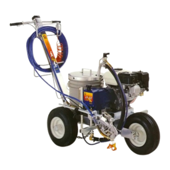
Page 5: Component Identification And Function
Component Identification and Functio 0015 0016 06941B Fig. 1 Pressure Control Switch ON/OFF, enables/disables clutch function Pressure Adjusting Knob Controls fluid outlet pressure Air Cleaner* Filters air entering the carburetor Fuel Tank* Holds 0.66 gallons (2.5 liters) of [(R+M)/2]; 86 octane gasoline Muffler* Reduces noise of internal combustion Spark Plug Cable*... -
Page 6: Setup
Setup 2. Fill packing nut/wetcup. Fill the packing nut/wet- CAUTION cup (B) 1/3 full with Graco Throat Seal Liquid (TSL), supplied. See Fig. 2. To avoid damaging the pressure control, which may result in poor equipment performance and component damage, follow these precautions. - Page 7 Setup 4. GROUNDING. Be sure your system is properly CAUTION grounded before flushing or fueling it. Connect the sprayer to a true earth ground with the Close the black fuel shutoff lever whenever you are grounding wire and clamp (76) ; for example, a transporting the sprayer to prevent fuel from flooding cold water pipe, a metal fence post or a metal rod the engine.
-
Page 8: Fueling
Fueling 2. Gasolines containing alcohol (gasohol). Do not WARNING use gasohol which contains methanol, if the gaso- hol does not contain cosolvents and corrosion FIRE AND EXPLOSION HAZARD inhibitors for methanol. Even if it does contain such Gasoline is extremely flammable and additives, do not use the gasohol if it contains explosive under certain conditions. -
Page 9: Startup
Startup Before You Start the LineLazer 6. To start the engine: 1. See Flushing on page 17 to determine if you a. Turn the pressure adjusting knob all the way should flush the LineLazer. counterclockwise to the lowest pressure set- ting. - Page 10 Startup 10. Prime the pump: If the pump was primed with water or solvent, remove the suction tube from the water or solvent and place it in the paint. Repeat steps a. Place the suction tube in the bucket of paint, c.
- Page 11 Startup 12. Install the spray tip in the gun. Sprayer is supplied with tip LL5317. For additional applications, use the tip selection table as follows: LineLazer Tip Selection Table Tip Size Line Width Used For 286211* 2 inches Sport court – light film build LL5213* 2 inches Sport court –...
-
Page 12: Spray Techniques
Spray Techniques These spray techniques discuss how to use and adjust 7. To minimize the effect of bumps on the spray pattern, the features of the LineLazer. You must also consider op- keep the spray tip guard centered with the front erator technique, job site conditions and weather. -
Page 13: Positioning The Gun Arm Assembly
Positioning the Gun Arm Assembly PUMP SIDE ENGINE SIDE 06943B Fig. 4 The gun arm can be positioned for a variety of spraying 2. Loosen the gun holder knob (40r) and remove the needs. The drawings on page 14 show the gun mounted gun. -
Page 14: Gun Arm Positions
Gun Arm Positions LINE SPRAYING CURB SPRAYING 06920 How To Mount the Gun 1. Relieve pressure. See page 17. How to Release the Gun Selector Cable 2. Disengage the trigger cable. See page 14. Engage WARNING the gun’s trigger safety latch (B). The gun is remotely triggered with a gun selector 3. - Page 15 How To Mount the Gun Trigger Cable Tension Adjustment See Fig. 6 FORWARD 1. Relieve pressure. See page 17. 2. Be sure the gun is properly mounted in the holder as instructed on page 14. 3. Pull the actuator lever (40s) forward and hold it. Lift up on the gun trigger (A) until there is slight resis- tance.
-
Page 16: Maintenance
Maintenance WARNING CAUTION INJECTION HAZARD For detailed engine maintenance and specifications, refer to the separate engine manual, supplied. To reduce the risk of serious injury, whenever you are instructed to relieve pressure, follow the Pressure Relief Procedure on page 17. DAILY: Check the engine oil level and fill as neces- WEEKLY: Check the level of the TSL in the displace- sary. -
Page 17: Flushing
Pressure Relief Procedure 1. Engage the gun safety latch. WARNING 2. Turn the engine switch to OFF. 3. Move the pressure control ON/OFF switch to OFF. INJECTION HAZARD 4. Disengage the gun safety latch. Hold a metal part The system pressure must be manually of the gun firmly to a grounded metal pail. - Page 18 Flushing How to Flush 6. Follow Startup on page 9. Keep the gun trig- gered until clean solvent comes from the nozzle. Release the trigger and lock the gun trigger safety. CAUTION When changing fluids, do not drain all of the first fluid CAUTION from the suction tube before inserting the suction tube into another fluid.
-
Page 19: Troubleshooting
Have the pressure control checked by an au- thorized Graco dealer. The clutch is worn, damaged, or incorrectly Replace the clutch. See page 28. positioned. - Page 20 Troubleshooting PROBLEM CAUSE SOLUTION The inlet screen (86) is clogged. Clean the screen. The pump output is low on the upstroke the upstroke. A piston ball (121) is not seating. Service the piston ball–check. See page 35. The piston packings are worn or damaged. Replace the packings.
-
Page 21: Drive Housing, Connecting Rod, Crankshaft
Drive Housing, Connecting Rod, Crankshaft 6. Remove and inspect the crankshaft (8) and the WARNING connecting rod (10). INJECTION HAZARD To reduce the risk of serious injury, Installation whenever you are instructed to relieve pressure, follow the Pressure Relief 7. Lubricate the inside of the drive housing bronze Procedure on page 17. - Page 22 Drive Housing, Connecting Rod, Crankshaft Ref A Torque to 100 in–lb (11 N.m) Quantity of three Quantity of one Lubricate with SAE non-detergent oil 06923 Fig. 8 Brush G-n lubricant and recoat with bearing grease Pack with bearing grease (0.22 pint) Fig.
-
Page 23: Pressure Control
Pressure Control 7. Loosely install the screws (34) and then torque WARNING them to 21 in–lb (2.4 N.m). INJECTION HAZARD 8. Install the front cover (9). Connect the harness (A) To reduce the risk of serious injury, to the control module leads (B). whenever you are instructed to relieve pressure, follow the Pressure Relief Procedure on page 17. -
Page 24: Control Module
Control Module 303 304 63 WARNING INJECTION HAZARD To reduce the risk of serious injury, whenever you are instructed to relieve pressure, follow the Pressure Relief Procedure on page 17. NOTE: See Fig. 11 for this procedure. 1. Relieve pressure. 2. -
Page 25: Pressure Transducer
Pressure Transducer WARNING INJECTION HAZARD To reduce the risk of serious injury, whenever you are instructed to relieve pressure, follow the Pressure Relief Procedure on page 17. NOTE: See Fig. 12 for this procedure. 1. Remove the displacement pump. See page 35. 2. -
Page 26: Pinion, Clutch, Clamp, Field, & Engine
Pinion, Clutch, Clamp, Field, & Engine If servicing clutch components only, see page 28. 8. Reassemble to drive housing. If no service is needed for internal parts of pinion CAUTION housing, remove drive assembly (drive and pinion housing) from clutch housing. See page 28. Do not lose the thrust ball (2d). -
Page 27: Pinion Housing
Pinion Housing Lubricate inner and Detail A outer diameters Lubricate teeth Directional arrow on roller clutch must face the small bearing (2n) Lubricate exterior Back of pinion housing 1.53 Press fit small bearing (2n) and clutch roller (s) here 06005 Fig. -
Page 28: Clutch
Clutch NOTE: The engine must be removed before the clamp 3. Pull the drive assembly (D) away from the clutch and clutch housing can be removed. housing (1). WARNING 4. The armature (51b) will move with the drive as- sembly. Remove the armature from the pinion hub (2h). - Page 29 Clutch 06928B Fig. 17 308685...
-
Page 30: Engine
CAUTION The engine for this sprayer is manufactured by Honda to a special Graco specification. The sprayer will experience poor clutch life, not work at all, or burn up the clutch coil if a replacement engine is purchased from another vendor. -
Page 31: Field & Wiring Harness
Field & Wiring Harness NOTE: Refer to Fig. 20. 1. Back out the four setscrews (30) holding the field (53) to the clutch housing (1) approximately 3 turns. 2. Pull out the field. The field fits closely to the clutch housing and must be removed carefully to prevent jamming. -
Page 32: Reassembly
Reassembly To check the dimension, place a rigid, straight CAUTION steel bar (B) across the face of the clutch housing (1). Use an accurate measuring device to measure The sprayer will be out of balance when only the the distance between the bar and the face of the engine and clutch housing are installed. - Page 33 Reassembly The face of the housing. CAUTION 1.41 ".010 inch (35.8 ".25 mm). The sprayer will be out of balance when only the Torque the screws to engine and clutch housing are installed. Support the 120 in–lb (14 N.m). rear of the cart to prevent the sprayer from falling over.
- Page 34 Reassembly 6. Be sure the face of the rotor (51a) and the clamp 8. Clean the face of the armature (51b). With the flat (55) are free of all burrs . Install the rotor, lock- side of the armature facing the rotor (51a), slide washers (16) and capscrews (56).
-
Page 35: Displacement Pump Repair
Displacement Pump Repair Removing the pump (See Fig. 26.) WARNING 1. Flush the pump, if possible. Relieve pressure. Stop INJECTION HAZARD the pump with the piston rod (107) in its lowest To reduce the risk of serious injury, position, if possible. whenever you are instructed to relieve pressure, follow the Pressure Relief 2. - Page 36 7. Reconnect the suction and drain hoses. Install the front cover (9). 8. Tighten the packing nut (102) just enough to stop leakage, but no tighter. Fill the packing nut/wet-cup 1/3 full with Graco TSL. Push the plug (123) into the wet-cup. 308685...
-
Page 37: Pinion Assembly Parts List And Drawing
239512 to apply to your sprayer. The drawing below shows Line indicator accessory for consistently straight lines. the best placement of these labels for good visibility. Order the labels directly from Graco, free of charge. Toll Free: 1–800–328–0211 Apply other... -
Page 38: Sprayer Parts Drawing
Sprayer Parts Drawing Model 232650 60 Ref 06939A Label See page 37 for the parts. 308685... -
Page 39: Sprayer Parts List
Sprayer Parts List Model 232650, Series A Ref. Ref. Part No. Description Qty. Part No. Description Qty. 191207 HOUSING, clutch 157191 ADAPTER 238684 HOUSING, pinion 238798 CLUTCH ASSEMBLY 100069 BALL ROTOR, clutch 238691 DRIVE HOUSING ARMATURE, clutch 176904 LABEL, designation 238803 FIELD, clutch 235558... - Page 40 Sprayer Parts Drawing Model 232650 06930B 39h Ref. 39k Ref. 68 43 Label 06940B 308685...
- Page 41 Sprayer Parts List Model 232650, Series A Ref. Ref. Part No. Description Qty. Part No. Description Qty. 114678 BUSHING, snap 100022 CAPSCREW, hex head 238961 SUCTION/DRAIN ASSY (includes 100020 WASHER, lock items 39a thru 39p) 112405 NUT, lock, 3/4–16 100014 SCREW, cap, hex head, .
-
Page 42: Pivoting Gun Arm Parts List And Drawing
Pivoting Gun Arm Parts List and Drawing Assembly 239273 Ref. Ref. Part No. Description Qty. Part No. Description Qty. 111721 CABLE, remote trigger 108483 SCREW, shoulder, sch, 224096 BRACKET, gun support 1 1/4 x 3/8 in. 114029 CLAMP, arm support 181795 JAW, clamp 188135... -
Page 43: Technical Data
238672 Pressure Control Parts List Part No. Description Part No. Description 238676 CONDUCTOR, electrical 280340 HOUSING, box, junction 312** 191242 PLATE, module 238660** TRIAC 105679 SWITCH, toggle 100035 SCREW, panhead, 10–24 x 2 inch 105658 RING, locking 157021** LOCKWASHER, No. 10 105659 BOOT, toggle 108783**... -
Page 44: Dimensions
Graco distributor to the original purchaser for use. With the exception of any special extended or limited warranty published by Graco, Graco will, for a period of twelve months from the date of sale, repair or replace any part of the equipment determined by Graco to be defective.
Need help?
Do you have a question about the LineLazer 3000 and is the answer not in the manual?
Questions and answers
Can I purchase the control knob on the transducer? The top section of it.