
Related Manuals for Telular TG-1 Express

Summary of Contents for Telular TG-1 Express
- Page 1 Express TG-1 Installation Guide COMPANY CONFIDENTIAL ® For use by TELGUARD customers only. Distribution to other parties strictly prohibited. June 21, 2012 56044702 © 2012 Telular Corporation...
-
Page 2: Important Note
The Telguard model TG-1 Express cellular alarm communicator is UL Listed for Household Fire systems and Household Burglary systems. This means that the TG-1 Express may be used in Household Burglary systems, Household Fire systems or combined Household Burglary &... - Page 3 It is our goal at Telular to always supply accurate and reliable documentation. If a discrepancy is found in this documentation, please mail or fax a photocopy of the corrected material to:...
- Page 4 System please contact Telguard Technical Support for troubleshooting. Repair of this equipment should only be referred to Telular. Telular will repair or replace (our option) inoperative units for up to two years from date of manufacture. This excludes damage due to lightning or installer error.
- Page 5 Moreover, arrangements should also be made for on-site inspection/test by a licensed alarm installer at least once each year. 56044702 © 2012 Telular Corporation...
- Page 6 Terms and Conditions for Use of Telular Product These Terms and Conditions are a legal contract between you and Telular Corporation for the title to and use of the Product. BY RETAINING AND USING THE PRODUCT YOU AGREE TO THE TERMS AND CONDITIONS INCLUDING WARRANTY DISCLAIMERS, LIMITATIONS OF LIABILITY AND INDEMNIFICATION PROVISIONS BELOW.
- Page 7 WARRANTY and LIMITATIONS TELULAR WILL REPAIR OR REPLACE (OUR OPTION) INOPERATIVE UNITS FOR UP TO TWO YEARS FROM DATE OF MANUFACTURE. EXCLUDES DAMAGE DUE TO LIGHTNING OR INSTALLER ERROR AS WELL AS UNITS THAT INCORPORATE MATERIAL, OR USED IN A MANNER OR ENVIRONMENT, NOT SPECIFICALLY AUTHORIZED IN THIS MANUAL.
-
Page 8: Table Of Contents
Table of Contents Important Note Foreword Table of Contents viii General Description and Operation Visual Tour TG‐1 Express – First Look Features Operating Mode Panel‐Supplied Power Single Line Interface Cable (SLIC) Multiple Alarm Format Support Complete Supervision of Communication Path Telguard Automatic Self‐test Report Telguard Remote Query Capability Programmable Supervisory Trip Output (STC) Relay Diagnostic and Status LEDs 2‐Way Voice UL Listings Getting Ready 56044702 viii © 2012 Telular Corporation... - Page 9 Dealer Account Establishment Subscriber Account Registration Pre‐Installation Checklist Installation Summary Step 1: Register the Telguard Unit for Service Step 2: Locate Unit and Measure Signal Strength (RSSI) Step 3: Program, Activate & Transmit Alarms Step 4: Connect the Supervisory Trip Output Step 5: Connect and Test the Trip Input (optional) Step 6: Complete the Telguard Installation Appendix 1 – Connection Guide Appendix 2 – Troubleshooting Guide Appendix 3 – Detailed Specifications Dialer to Interface Electronics Power Consumption Digital Cellular Radio Appendix 4 – Parts List 56044702 © 2012 Telular Corporation...
-
Page 10: General Description And Operation
(Public Switched Telephone Network - PSTN) to the appropriate alarm company central station for action. In a typical alarm installation, Telguard Digital TG-1 Express is installed in the same area as the host alarm system and is connected directly to the host alarm panel via the Telguard’s RJ-45 jack in the normal... -
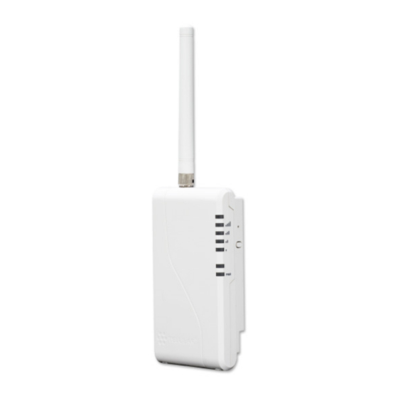
Page 11: Visual Tour
Telguard unit’s operating conditions. These conditions include programming setup information, alarm transmission information, supervisory trouble information, status information, and automatic self-test information. Visual Tour TG-1 Express – First Look 56044702 © 2012 Telular Corporation... -
Page 12: Features
Inside the TG-1 Express Features This section summarizes the key features of the Telguard TG-1 Express. Operating Mode The Telguard Digital TG-1 Express is a digital cellular transmission device that is installed at the protected premises to provide primary alarm transmission integrity for household burglary and fire systems. -
Page 13: Panel-Supplied Power
At 45mA (average consumption WHILE IDLE), the power required by the TG-1 Express is about the same as that is used by many keypads. Simply connect the Auxiliary power output from any voltage compatible (6.2V to 17V) panel to the DC input on the TG-1Express. -
Page 14: Complete Supervision Of Communication Path
The Telguard TG-1 Express continuously supervises the primary (cellular) communication path. If the cellular communications path becomes inoperative, the TG-1 Express generates a relay trip output that can be connected to a zone input of the host alarm panel and/or used to activate remote annunciation devices. -
Page 15: Telguard Automatic Self-Test Report
Telguard Automatic Self-test Report The Telguard automatic self-test signal is programmed to daily, weekly or monthly schedule as prescribed by contract. The central station receives the automatic self-test report in the same format that the 56044702 © 2012 Telular Corporation... -
Page 16: Telguard Remote Query Capability
Center for review and is not forwarded on to the central station. Programmable Supervisory Trip Output (STC) Relay The Telguard Digital TG-1 Express has one supervisory relay trip output (STC) and is energized in a powered-up state when no system troubles exist. -
Page 17: Diagnostic And Status Leds
The following system trouble features are embedded in the Telguard for tripping the STC relay and cannot be changed: Tripped when unit is not activated at the Telular Communications Center (TCC) Trips on catastrophic failure (CF) if all power is lost. -
Page 18: Ul Listings
UL Listings Model TG-1 Express meets the requirements for all Household Burglary, Household Fire, and Combined Household Burglary/Fire installations. It has a plastic enclosure and dipole antenna. TG-1 Express is UL and ULC Listed for the following: UL Household Burglary (UL 1023) ... -
Page 19: Subscriber Account Registration
Subscriber Account Registration A completed Registration Form is required by Telular to register the Telguard unit prior to leaving for the job site. Service registration of the Telguard can be accomplished: Online – Complete the Registration Form online at www.telguardonline.com... -
Page 20: Installation
A standard RJ31X-to-spaded leads cable will be required to connect the TG-1 Express to the panel. These are usually supplied with the alarm panel. Note: Your unit may be subject to airtime charges for unintended use. Telular Cellular Service offers several cellular service rate plans. -
Page 21: Step 1: Register The Telguard Unit For Service
Note that for a UL compliant installation, the Telguard TG-1 Express must be mounted in the same room as, and not more than 20ft from the alarm panel. - Page 22 TG-1 Express. Reconnect the alarm panel’s power supply, and ensure that the PWR light (LED 8) on the TG-1 Express is illuminated. To connect power to the TG-1 Express using the POTS connection: Using a standard RJ-31X to spaded lead cable, connect the orange and blue leads to the GND and PWR terminals of the alarm panel respectively.
- Page 23 Note 2: To avoid interference with other electronic devices operating in the area, avoid mounting the Telguard’s antenna near other electronic devices. Note 3: The Telguard TG-1 Express unit with supplied dipole antenna is designed for indoor installations ONLY. These considerations should be coupled with the best RSSI indication obtainable.
- Page 24 If you cannot obtain a signal strength reading of 2½ (TWO LEDS ON SOLID AND THE THIRD LED ON SLOW FLASH), you will probably need to move the unit and/or remote antenna higher, or switch to a special antenna as described below. 56044702 © 2012 Telular Corporation...
-
Page 25: Step 3: Program, Activate & Transmit Alarms
If you require a higher gain antenna or a longer cable assembly please contact your Telular Sales Representative at 800-229- 2326, option 5. Telular offers a variety of high quality low loss antenna cables as well as high gain antennas. - Page 26 3 FLASH 4 FLASH NSC – No Service 5 FLASH RFC – Radio Failure 6 FLASH DTF – Dial Tone Failure 7 FLASH PPF – Panel Presence Failure System Trouble Condition, STC (LED #2) Table 56044702 © 2012 Telular Corporation...
- Page 27 Connect Alarm Panel to TG-1 Express If the alarm panel and the TG-1 Express were not already connected in Step 2, plug the modular jack of the alarm panel to the RJ-45 jack on the Telguard. Set Up & Program the Operating Parameters in the...
- Page 28 0 = disabled, 1 = 10 seconds, 2 = 20 Timer seconds, … 15 = 150 seconds Trip Input 0 = no report Reporting 1 = report trip Trip Input 0 = no report Restoral 1 = report restoral Reporting 56044702 © 2012 Telular Corporation...
- Page 29 Telguard. After the panel has finished communicating with the Telguard unit, LED #4 will come on solid while waiting for an acknowledgement from the Telular message center. If you are having problems getting reliable alarm signal transmissions, additional adjustments may be necessary.
-
Page 30: Step 4: Connect The Supervisory Trip Output
Verify Audio Connectivity (optional) The TG-1 Express supports transmit and receive audio, if used with a listen-in alarm panel and configured with the voice feature at the Telguard Message Center. If the audio capability is being used, it is important to verify proper voice communication. - Page 31 Restoral of this condition occurs when a measurable signal strength greater than –114 dBm is maintained for the trip period. RFC: Trips on radio failure to communicate with the Telular Communication Center DTF: Trips on an internal failure in the dial tone circuitry within the TG-1 Express ...
-
Page 32: Step 5: Connect And Test The Trip Input (Optional)
Step 5: Connect and Test the Trip Input (optional) In addition to the interface to the alarm panel, a single trip input may be connected to the terminal block of the TG-1 Express. When the input is tripped, a supervisory message is sent to the central station via the Telguard Message Center. - Page 33 The trip input is connected to the external relay by wiring one side of the external relay to the TRIP IN terminal, and the other side to either the GND terminal or to the chassis ground on the TG-1 Express circuit board.
-
Page 34: Step 6: Complete The Telguard Installation
Telguard enclosure. Install the mounting screws (not supplied). The “keyhole” mounting holes on the back of the TG-1 Express are 2.5” apart, center-to-center. Slide the enclosure onto these screws. -
Page 35: Appendix 1 - Connection Guide
Wiring Diagram Attaching the RJ-45 Cable The RJ-45 cable to the panel can be attached to the TG-1 Express either with the enclosure open or closed. A notch in the rear opening of the enclosure is provided to allow better cable access. Note that, as with other Telguard products, the RJ-45 cable to the panel, as well as all other wiring, should be routed through the rear cable opening, to allow the plastic lid of the TG-1 Express to be closed properly. - Page 36 5 PWR alarm panel Compatible Alarm Panels The TG-1 Express is compatible with all popular alarm panels and many specialized panels as well. For a complete listing of panels for which the TG-1 Express is UL 56044702 © 2012 Telular Corporation...
-
Page 37: Appendix 2 - Troubleshooting Guide
Appendix 2 – Troubleshooting Guide This section provides a summary of all LED indications and their meanings, as well as the expected behavior of the TG-1 Express under various exception conditions. LED Indicator Guide – Normal Operating Mode LED Symbol... - Page 38 When flashing with LED #1 unit Flashing has failed activation.0 CALL TELGUARD TECHNICAL SUPPORT LED #4 Acknowledgem TG-1 Express initialized TG-1 Express is waiting for response from Telular Communication Center Short Flash (1 Radio receiving message sec) LED #5 Green...
- Page 39 LED 2 = off strength required) LED 5-3 = on, LED 2 = off -80 dBm 3½ LED 5-3 = on, LED 2 = slow flash -70 dBm LED 5-2 = on -60 dBm 56044702 © 2012 Telular Corporation...
- Page 40 Configuration None during data TCC and switches to Upload transmit READY state. Radio LED Disable TX – TX capability is #5 flashes Communication (Status disabled until further when notice. Center Activated. data) transmitting 56044702 © 2012 Telular Corporation...
-
Page 41: Appendix 3 - Detailed Specifications
17Vdc, 38mA(idle), 124mA (transmitting) Digital Cellular Radio The Telguard TG-1 Express is a 3G radio that supports GSM/GPRS and UMTS cellular protocols. It is equipped with an integrated radio transceiver conforming to all the requirements of the GSM Phase 2+ tests specified in GSM 11.10. - Page 42 FCC ID: N7NSL8080 Supplied Antenna: Dipole Physical Size: 5.6"H x 2.9"W x 1.3"D. Shipping weight: 1.1 lbs. ° ° Operating Environment: 0 C to +49 C; 0 - 85% humidity (non-condensing). 56044702 © 2012 Telular Corporation...
-
Page 43: Appendix 4 - Parts List
Appendix 4 – Parts List Basic Hardware: Model TG-1 Express Model TG-1 Express meets the requirements for Household Burglary, Household Fire, and Combination Burglary/Fire installations. It has a plastic enclosure, and dipole antenna. General Accessories: CTX-12 12 feet SMA/TNC antenna cable and mounting bracket. - Page 44 Telguard cellular communicator instead of a traditional landline. Wireless protection is the most reliable form of security because the communication path isn’t susceptible to being cut or lost due to inclement weather. 56044702 © 2012 Telular Corporation...
Need help?
Do you have a question about the TG-1 Express and is the answer not in the manual?
Questions and answers