Electrolux W4400H Installation Manual
Washer extractors
Hide thumbs
Also See for W4400H:
- Service manual (186 pages) ,
- Brochure & specs (4 pages) ,
- Operating manual (24 pages)

Related Manuals for Electrolux W4400H


Summary of Contents for Electrolux W4400H
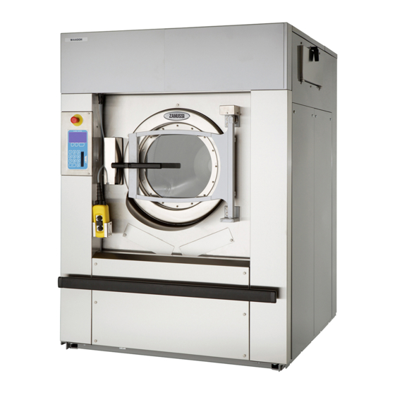
- Page 1 Installation manual Washer extractors W4400H, W4600H, W4850H, W41100H Type W4.H. Clarus Control Installation manual in original language 438 9211-81/EN 2011.01.31...
-
Page 3: Table Of Contents
Contents Contents Safety Precautions ..................5 Technical data ....................7 Installation ....................11 Location and surface ................11 Mechanical installation ................11 Machine equipped with weight measurement ........11 Connecting the water supply ..............16 Steam supply ..................17 Compressed air connection ..............18 Drain ....................20 Ventilation ....................20 Detergent dispenser, non-liquid detergents ........21 Installation of equipment for external liquid supply ......21 Electrical installation ................22 Tilt function (optional equipment) ............26... -
Page 5: Safety Precautions
Safety Precautions Safety Precautions The machine is only intended for water-wash use. Do not allow minors to use the machine. Do not hose down the machine with water. The machine's door lock must under no circumstances be bypassed. If the machine develops a fault, this must be reported to the person in charge as soon as possible. -
Page 7: Technical Data
Technical data Technical data W4400H W4600H W4850H W41100H Innerdrum volume litres 1100 diameter 1220 1220 Drum speed wash extraction Heating electricity 36 or 54 – – steam hot water G-factor Weight, net 1095-1450* 1380-1480 2200-2300* 2300-2400* Sound pressure level dB (A) * Precise weight depends on accessories fitted. - Page 8 Technical data Dimensions W4400H 1325 1450 2015 910 300 1865 270 660 525 425 895 1425 420 435 2205 1140 2235 950 345 370 W4600H 1390 1585 2015 910 300 1865 270 660 525 425 960 1425 420 435 2200 1120 2225 935 300 325...
-
Page 9: Technical Data
Technical data Dimensions W4850H 1640 1635 2230 995 380 2135 1070 830 635 445 1140 1660 435 820 2410 1175 2480 960 285 400 W41100H 1640 1850 2230 995 380 2135 1070 830 635 445 1140 1660 435 820 2400 1160 2480 955 240 335 Control panel Steam connection Drain... - Page 10 Technical data Technical data W4400H W4600H W4850H W41100H Frequency of the 13.8 12.7 12.0 11.1 dynamic force Max floor load 15.8 ± 1.2 15.9 ± 6.4 22 ± 7.3 24 ± 7.3 at extraction Sound levels Airborne sound level dB (A) re 2x10 <...
-
Page 11: Installation
Installation Installation For the installation of machines with optio- nal equipment (such as the tilt function), 0,5 m see also the section ”Optional equipment” 500 mm 1000 mm at the end of this manual. The washer extractor is supplied bolted in place on a pallet and packaged in a delivery crate. - Page 12 Installation • Use a fork-lift truck to lift the machine. • Position the four blocks of wood supplied, one beneath each machine foot (on the outer frame), within the recesses in the pallet. 5545 7222...
- Page 13 Installation • Lower the machine (A) and withdraw the truck forks (B). The machine should now be stan- ding on the four blocks, and the pallet will be on the floor, clear of the machine. The next step is to insert the truck forks very carefully between machine and pallet (C). • Lift the machine and remove pallet and blocks.
- Page 14 Installation • Put the machine in place. Mark out and drill the holes for fixing the feet. Hole diameter: 15 mm. 5550, 6056 For standard machines W4400H W4600H W4850H W41100H 1325 1390 1640 1640 1445 1605 1635 1850 1160 1315 1370 1585 1310 1370 1610 1610 For machines with tilt or weighing function...
- Page 15 Installation Use a spirit level and, where necessary, the ”washers” (or rectangular metal plates) supplied, to ensure that the floor mountings are level. • Put the machine in place. Use a spirit level on suitable surfaces of the outer frame to check that the machine is level. Check too that the machine is resting firmly on all four feet.
-
Page 16: Connecting The Water Supply
Connect the hoses as follows: • cold water to (A) • hot water to (B) • (if using a third water supply:) the third water hose to (C). W4400H, W4600H Sizes of A, B and C: DN 25 (1" BSP). W4850H, W41100H Sizes of A, B and C: DN 32 (1 1/4" BSP). -
Page 17: Steam Supply
• recommended: 300-600 kPa • limiting values, min: 50 kPa max: 800 kPa The hose should hang in a gradual arc. This is particularly important if the machine is fitted with W4400H, W4600H 4138 a tilting function. W4400H, W4600H Connection size: DN 20 (3/4" BSP). -
Page 18: Compressed Air Connection
Installation Compressed air connection A pressure regulator complete with water sepa- ration device is to be installed on the machine. When the machine is supplied, the angled coup- ling (1), hose (2) and bracket (3) for the pressure regulator will already be installed. Install the quick-connector for the hose and a bushing (for the hose from the compressed air supply) on the pressure regulator. - Page 19 Installation Connect the hose from the compressed air supply to the bushing on the pressure regulator. Connect the hose so it hangs in a gentle arc. This is particularly important if the machine has the tilt function. The connecting hose must be rated for a pressure of at least 1 MPa.
-
Page 20: Drain
Installation Drain The connector for the machine discharge (A) has an external diameter of 110 mm. The distance between the machine and the floor gully or drai- nage channel should be at least 250 mm. Connect a hose or a pipe to the drain connec- tion. -
Page 21: Detergent Dispenser, Non-Liquid Detergents
Installation Detergent dispenser, non-liquid detergents If only non-liquid detergents are to be used in the detergent dispenser, the following adapta- tion is recommended: Drill two 5 mm holes in the bottom of each scoop to allow any water left to drain off. Installation of equipment for external liquid supply Electrical installation may only be carried... -
Page 22: Electrical Installation
Installation Electrical installation Electrical installation may only be carried out by competent, authorised personnel. Check that the earth conductor is correctly connected. The electrical cable for the machine's power L1 L2 L3 supply should hang in a gentle arc. This is parti- cularly important if the machine is equipped with the tilt function or weighing equipment. - Page 23 Installation Heating Voltage Total Fuse alternative alternative 200 V 3 AC No heating 208-240 V 3 AC or Steam 230/400 V 3 AC 25/16 heating 240 V 3 AC 346 V 3 AC 380 V 3 AC 400 V 3 AC 415 V 3 AC 440 V 3 AC 480 V 3 AC...
- Page 24 Installation W4600H Heating Voltage Total Fuse alternative alternative 200 V 3 AC No heating 230 V 3 AC or Steam 230 V 3 AC heating 240 V 3 AC 240 V 3 AC 380 V 3 AC 400 V 3 AC 415 V 3 AC 440 V 3 AC 480 V 3 AC...
- Page 25 Installation W4850H Heating Voltage Total Fuse alternative alternative 200 V 3 AC No heating 230 V 3 AC or Steam 240 V 3 AC heating 380 V 3 AC 400 V 3 AC 415 V 3 AC 440 V 3 AC 480 V 3 AC W41100H Heating...
-
Page 26: Tilt Function (Optional Equipment)
Tilt function (optional equipment) Tilt function Installation Remove the machine’s side panels, lower front panel and rear covers. 3449 For machines with tilt both forwards and back- wards: Insert the two cylinder units from the side of the machine underneath the machine frame. If there is vinyl floor-covering on the floor: To protect the floor from wear, a sheet of stain- less steel should be laid beneath each cylinder... - Page 27 Tilt function (optional equipment) Secure the cylinder units using four bolts and nuts. It is important to fit four washers (each 5 mm thick) between each cylinder unit and the machine frame (see illustration). 4 washers 4 washers 3453 Fit the four corner posts, one for each corner of the machine, using the bolts which secure the machine feet to the floor.
- Page 28 Tilt function (optional equipment) For machines with tilt both forwards and back- wards: The compressed air lines which are to be con- nected to the air bellows and position sensors are supplied bundled on the machine rear. Connect the lines to the air bellows and pressure sensors according to the table below.
- Page 29 Tilt function (optional equipment) For machines with forward tilt only: The compressed air line to be connected to the air bellows is supplied bundled on the machine rear. Connect this line to the connection nipple on the top of the bellows. 6049...
- Page 30 Tilt function (optional equipment) Test the tilt function: • Switch on the machine electrical switch(es) and turn on the compressed air supply. • Open the door and lock it open. • The uppermost switch on the tilt control unit tilts the machine either backwards (turn switch anticlockwise) or forwards (turn switch clockwise). The middle switch returns the machine to its normal (upright) position.
- Page 31 Tilt function (optional equipment) Position and fasten the side panel strips. 3486 Fit the two counterweights to the front panel strip. The bolt heads should be at the bottom. Counterweights 3487 Hang the front panel strip on the two sleeves you fitted to the side strips.
- Page 32 Electrolux Laundry Systems Sweden AB 341 80 Ljungby, Sweden www.electrolux.com/laundrysystems Share more of our thinking at www.electrolux.com...