Table of Contents
Advertisement
Quick Links
Advertisement
Table of Contents

Subscribe to Our Youtube Channel
Related Manuals for Black Box L2 Plus


Summary of Contents for Black Box L2 Plus
- Page 3 16-Port SFP + 8-Port Combo GbE L2 Plus Managed Switch...
-
Page 5: Table Of Contents
Table of Contents ............................. 7 AUTION ......................7 LECTRONIC MISSION OTICES INTRODUCTION ........................9 1-1. O LGB1005A-R2 ..................... 9 VERVIEW OF 1-2. C ..........................12 HECKLIST 1-3. F ........................... 12 EATURES 1-4. V LGB1005A-R2......................14 IEW OF 1-4-1. User Interfaces on the Front Panel (Button, LEDs and Plugs)......... 14 1-4-2. - Page 6 3-4-2. Static Filter........................26 3-4-3. Static Forward........................27 3-4-4. MAC Alias ......................... 28 3-4-5. MAC Table......................... 29 3-5. GVRP ............................30 3-5-1. Config..........................30 3-5-2. Counter..........................33 3-5-3. Group ..........................35 3-6. Q ................36 UALITY OF ERVICE ONFIGURATION 3-6-1. Ports ..........................36 3-6-2.
- Page 7 3-20-1 . Diag..........................152 3-20-2 .Ping ..........................153 3-20-2 .VeriPHY......................... 154 3-21 M ........................155 AINTENANCE 3-21-1 .Reset Device ........................155 3-21-2 .Software Upload......................155 3-22 L ..........................156 OGOUT OPERATION OF CLI MANAGEMENT ................157 4-1. CLI M ........................157 ANAGEMENT 4-1-1.
-
Page 8: Revision History
Revision History Release Date Revision 0.91 2008/ 03/03 0.95 2008/06/25 0.95 2008/07/21... -
Page 9: Caution
Caution Circuit devices are sensitive to static electricity, which can damage their delicate electronics. Dry weather conditions or walking across a carpeted floor may cause you to acquire a static electrical charge. To protect your device, always: • Touch the metal chassis of your computer to ground the static electrical charge before you pick up the circuit device. - Page 10 About this user’s manual In this user’s manual, it will not only tell you how to install and connect your network system but configure and monitor the LGB1005A-R2 through the built-in CLI and web by RS-232 serial interface and Ethernet ports step-by-step. Many explanation in detail of hardware and software functions are shown as well as the examples of the operation for web-based interface and command-line interface (CLI).
-
Page 11: Introduction
1. Introduction 1-1. Overview of LGB1005A-R2 LGB1005A-R2, a 24-port Gigabit L2 Plus Managed Switch, is a standard switch that meets all IEEE 802.3/u/x/z Gigabit, Fast Ethernet specifications. 16-Port 1000Mbps SFP and 8-Port Combo Gigabit TP/SFP Fiber dual media management Ethernet switch. - Page 12 • Key Features in the Device QoS: Support Quality of Service by the IEEE 802.1P standard. There are two priority queue and packet transmission schedule. Spanning Tree: Support IEEE 802.1D, IEEE 802.1w (RSTP: Rapid Spanning Tree Protocol) standards. VLAN: Support Port-based VLAN and IEEE802.1Q Tag VLAN. Support 256 active VLANs and VLAN ID 1~4094.
- Page 13 none of its other hosts belong, sends unsolicited group membership reports to that group. • When the last of its hosts in a particular multicast group leaves the group, sends an unsolicited leave group membership report to the all-routers group (244.0.0.2).
-
Page 14: Checklist
1-2. Checklist Before you start installing the switch, verify that the package contains the following: ⎯ LGB1005A-R2 24-port Layer 2 plus Gigabit Managed Switch ⎯ SFP Modules (optional) ⎯ Mounting Accessory (for 19” Rack Shelf) ⎯ This User's Manual in CD-ROM ⎯... - Page 15 • Supports 802.1Q VLAN • Supports user management and limits three users to login • Maximal packet length can be up to 9600 bytes for jumbo frame application • Supports DHCP Broadcasting Suppression to avoid network suspended or crashed • Supports to send the trap event while monitored events happened •...
-
Page 16: View Of Lgb1005A-R2
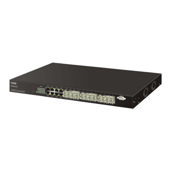
1-4. View of LGB1005A-R2 Fig. 1-1 Full View of LGB1005A-R2 1-4-1. User Interfaces on the Front Panel (Button, LEDs and Plugs) There are 8 TP Gigabit Ethernet ports and 24 SFP fiber ports for optional removable modules on the front panel of the switch. LED display area, locating on the left side of the panel, contains a Power LED, which indicates the power status and 24 ports working status of the switch. -
Page 17: Ac Power Input On The Rear Panel
• LED Indicators Color Function System LED POWER Green Lit when +5V DC power is on and good 10/100/1000Ethernet TP Port 1 to 8 LED Lit when connection with remote device is good LINK/ACT Green Blinks when any traffic is present Off when cable connection is not good Lit green when 1000Mbps speed is active Green/... -
Page 18: View Of The Optional Modules
1-5. View of the Optional Modules In the switch, Port 1~ 8 includes two types of media --- TP and SFP Fiber (LC, BiDi LC…); this port supports 10/100/1000Mbps TP or 1000Mbps SFP Fiber with auto- detected function. 1000Mbps SFP Fiber transceiver is used for high-speed connection expansion;... -
Page 19: Installation
2. Installation 2-1. Starting LGB1005A-R2 Up This section will give users a quick start for: Hardware and Cable Installation - Management Station Installation - Software booting and configuration 2-1-1. Hardware and Cable Installation At the beginning, please do first: ⇒ Wear a grounding device to avoid the damage from electrostatic discharge ⇒... - Page 20 • TP Port and Cable Installation ⇒ In the switch, TP port supports MDI/MDI-X auto-crossover, so both types of cable, straight-through and crossed-over can be used. It means you do not have to tell from them, just plug it. ⇒ Use Cat. 5 grade RJ-45 TP cable to connect to a TP port of the switch and the other end is connected to a network-aware device such as a workstation or a server.
-
Page 21: Installing Chassis To A 19-Inch Wiring Closet Rail
2-1-2. Installing Chassis to a 19-Inch Wiring Closet Rail Fig. 2-2 Caution: Allow a proper spacing and proper air ventilation for the cooling fan at both sides of the chassis. ⇒ Wear a grounding device for electrostatic discharge. ⇒ Screw the mounting accessory to the front side of the switch (See Fig. 2-2). ⇒... -
Page 22: Cabling Requirements For Tp Ports
2-1-3-1. Cabling Requirements for TP Ports ⇒ For Fast Ethernet TP network connection ⎯ The grade of the cable must be Cat. 5 or Cat. 5e with a maximum length of 100 meters. ⇒ Gigabit Ethernet TP network connection ⎯ The grade of the cable must be Cat. 5 or Cat. 5e with a maximum length of 100 meters. -
Page 23: Switch Cascading In Topology
2-1-3-3. Switch Cascading in Topology • Takes the Delay Time into Account Theoretically, the switch partitions the collision domain for each port in switch cascading that you may up-link the switches unlimitedly. In practice, the network extension (cascading levels & overall diameter) must follow the constraint of the IEEE 802.3/802.3u/802.3z and other 802.1 series protocol specifications, in which the limitations are the timing requirement from physical signals defined by 802.3 series specification of Media Access Control (MAC) and PHY, and timer from some OSI layer 2... - Page 24 Case1: All switch ports are in the same local area network. Every port can access each other (See Fig. 2-3). Fig. 2-3 No VLAN Configuration Diagram If VLAN is enabled and configured, each node in the network that can communicate each other directly is bounded in the same VLAN area. Here VLAN area is defined by what VLAN you are using.
- Page 25 Case 2b: Port-based VLAN (See Fig.2-5). Fig. 2-5 Port-based VLAN Diagram 1. VLAN1 members could not access VLAN2, VLAN3 and VLAN4 members. 2. VLAN2 members could not access VLAN1 and VLAN3 members, but they could access VLAN4 members. VLAN3 members could not access VLAN1, VLAN2 and VLAN4. 4.
-
Page 26: Configuring The Management Agent Of Lgb1005A-R2
2-1-4. Configuring the Management Agent of LGB1005A-R2 We offer you three ways to startup the switch management function. They are RS- 232 console, CLI, and Web. Users can use any one of them to monitor and configure the switch. You can touch them through the following procedures. Section 2-1-4-1: Configuring the Management Agent of LGB1005A-R2 through the Serial RS-232 Port Section 2-1-4-2: Configuring the Management Agent of LGB1005A-R2 through the... - Page 27 2-1-4-1. Configuring the Management Agent of LGB1005A-R2 through the Serial RS- 232 Port To perform the configuration through RS-232 console port, the switch’s serial port must be directly connected to a DCE device, for example, a PC, through RS-232 cable with DB-9 connector.
- Page 28 • Set IP Address, Subnet Mask and Default Gateway IP Address Please refer to Fig. 2-7 CLI Management for details about ex-factory IP setting. They are default setting of IP address. You can first either configure your PC IP address or change IP address of the switch, next to change the IP address of default gateway and subnet mask.
-
Page 29: Configuring The Management Agent Of Lgb1005A-R2 Through The Ethernet Port
2-1-4-2. Configuring the Management Agent of LGB1005A-R2 through the Ethernet Port There are three ways to configure and monitor the switch through the switch’s Ethernet port. They are CLI, Web browser and SNMP manager. The user interface for the last one is NMS dependent and does not cover here. We just introduce the first two types of management interface. -
Page 30: Ip Address Assignment
Fig. 2-10 the Login Screen for Web 2-1-5. IP Address Assignment For IP address configuration, there are three parameters needed to be filled in. They are IP address, Subnet Mask, Default Gateway and DNS. IP address: The address of the network device in the network is used for internetworking communication. - Page 31 With the classful addressing, it divides IP address into three classes, class A, class B and class C. The rest of IP addresses are for multicast and broadcast. The bit length of the network prefix is the same as that of the subnet mask and is denoted as IP address/X, for example, 192.168.1.0/24.
- Page 32 Class D and E: Class D is a class with first 4 MSB (Most significance bit) set to 1-1-1-0 and is used for IP Multicast. See also RFC 1112. Class E is a class with first 4 MSB set to 1-1-1-1 and is used for IP broadcast.
- Page 33 In this diagram, you can see the subnet mask with 25-bit long, 255.255.255.128, contains 126 members in the sub-netted network. Another is that the length of network prefix equals the number of the bit with 1s in that subnet mask. With this, you can easily count the number of IP addresses matched.
- Page 34 For different network applications, the subnet mask may look like 255.255.255.240. This means it is a small network accommodating a maximum of 15 nodes in the network. Default gateway: For the routed packet, if the destination is not in the routing table, all the traffic is put into the device with the designated IP address, known as default router.
-
Page 35: Typical Applications
2-2. Typical Applications The LGB1005A-R2 implements 8 Gigabit Ethernet TP ports with auto MDIX and two slots for the removable module supporting comprehensive fiber types of connection, including LC and BiDi-LC SFP modules. For more details on the specification of the switch, please refer to Appendix A. - Page 36 Fig. 2-14 Peer-to-peer Network Connection Fig. 2-15 Office Network Connection...
-
Page 37: Operation Of Web-Based Management
3. Operation of Web-based Management This chapter instructs you how to configure and manage the LGB1005A-R2 through the web user interface it supports, to access and manage the 16-Port Gigabit SFP and 8-Port Gigabit TP/SFP Fiber management Ethernet switch. With this facility, you can easily access and monitor through any one port of the switch all the status of the switch, including MIBs status, each port activity, Spanning tree status, port aggregation status, multicast traffic, VLAN and priority status, even illegal access record and so on. - Page 38 To optimize the display effect, we recommend you use Microsoft IE 6.0 above, Netscape V7.1 above or FireFox V1.00 above and have the resolution 1024x768. The switch supported neutral web browser interface. In Fig. 3-2, for example, left section is the whole function tree with web user interface and we will travel it through this chapter.
-
Page 39: Web Management Home Overview
3-1. Web Management Home Overview After you login, the switch shows you the system information as Fig. 3-2. This page is default and tells you the basic information of the system, including “Model Name”, “System Description”, “Location”, “Contact”, “Device Name”, “System Up Time”, “Current Time”, “BIOS Version”, “Firmware Version”, “Hardware-Mechanical Version”, “Serial Number”, “Host IP Address”, “Host Mac Address”, “Device Port”, “RAM Size”... - Page 40 • The Information of Page Layout ⎯ On the top side, it shows the front panel of the switch. In the front panel, the linked ports will display green; as to the ports, which are link off, they will be dark. For the optional modules, the slot will show only a cover plate if no module exists and will show a module if a module is present.
- Page 41 Root System Port VLAN GVRP SNMP IP MAC Binding 802.1X Trunk MSTP Mirroring IGMP Alarm Save/Restore Export/Import Diagnostics Maintenance Logout...
-
Page 42: System Information
Parameter description: Model name: The model name of this device. System description: As it is, this tells what this device is. Here, it is “L2 Plus Managed Switch”. Location: Basically, it is the location where this switch is put. User-defined. Contact: For easily managing and maintaining device, you may write down the contact person and phone here for getting help soon. - Page 43 Host IP address: The IP address of the switch. Host MAC address: It is the Ethernet MAC address of the management agent in this switch. Device Port: Show all types and numbers of the port in the switch. RAM size: The size of the DRAM in this switch.
-
Page 44: Account Configuration
3-1-2. Account Configuration In this function, only administrator can create, modify or delete the username and password. Administrator can modify other guest identities’ password without confirming the password but it is necessary to modify the administrator-equivalent identity. Guest- equivalent identity can modify his password only. Please note that you must confirm administrator/guest identity in the field of Authorization in advance before configuring the username and password. -
Page 45: Time Configuration
3-1-3. Time Configuration The switch provides manual and automatic ways to set the system time via NTP. Manual setting is simple and you just input “Year”, “Month”, “Day”, “Hour”, “Minute” and “Second” within the valid value range indicated in each item. If you input an invalid value, for example, 61 in minute, the switch will clamp the figure to 59. - Page 46 NTP: NTP is Network Time Protocol and is used to sync the network time based Greenwich Mean Time (GMT). If use the NTP mode and select a built-in NTP time server or manually specify an user-defined NTP server as well as Time Zone, the switch will sync the time in a short after pressing <Apply>...
- Page 47 Day Light Saving End : This is used to set when to stop performing the daylight saving time. Mth: Range is 1 ~ 12. Default: 1 Day: Range is 1 ~ 31. Default: 1 Hour: Range is 0 ~ 23. Default: 0 Fig.
-
Page 48: Ip Configuration
3-1-4. IP Configuration IP configuration is one of the most important configurations in the switch. Without the proper setting, network manager will not be able to manage or view the device. The switch supports both manual IP address setting and automatic IP address setting via DHCP server. - Page 49 IP address: Users can configure the IP settings and fill in new values if users set the DHCP function “Disable”. Then, click <Apply> button to update. When DHCP is disabled, Default: 192.168.1.1 If DHCP is enabled, this field is filled by DHCP server and will not allow user manually set it any more.
- Page 50 DNS: It is Domain Name Server used to serve the translation between IP address and name address. The switch supports DNS client function to re-route the mnemonic name address to DNS server to get its associated IP address for accessing Internet. User can specify a DNS IP address for the switch.
-
Page 51: Loop Detection
3-1-5. Loop Detection The loop detection is used to detect the presence of traffic. When switch receives packet’s(looping detection frame) MAC address the same as oneself from port, show Loop detection happens. The port will be locked when it received the looping detection frames. -
Page 52: Management Policy
3-1-6. Management Policy Through the management security configuration, the manager can do the strict setup to control the switch and limit the user to access this switch. The following rules are offered for the manager to manage the switch: Rule 1) : When no lists exists, then it will accept all connections. Accept ----------------------------------------------------------------------- Rule 2) : When only “accept lists”... - Page 53 Function name: Management Security Configuration Function description: The switch offers Management Security Configuration function. With this function, the manager can easily control the mode that the user connects to the switch. According to the mode, users can be classified into two types: Those who are able to connect to the switch (Accept) and those who are unable to connect to the switch (Deny).
- Page 54 The switch supports two kinds of options for managed valid VLAN VID, including “Any” and “Custom”. Default is “Any”. When you choose “Custom”, you can fill in VID number. The valid VID range is 1~4094. IP Range: The switch supports two kinds of options for managed valid IP Range, including “Any”...
-
Page 55: Virtual Stack
3-1-7. Virtual Stack Function name: Virtual Stack Function description: Virtual Stack Management(VSM) is the group management function. Through the proper configuration of this function, switches in the same LAN will be grouped automatically. And among these switch, one switch will be a master machine, and the others in this group will become the slave devices. - Page 57 Parameter description: State: It is used for the activation or de-activation of VSM. Default is Enable. Role: The role that the switch would like to play in virtual stack. Two types of roles, including master and slave are offered for option. Default is Master. Group ID: It is the group identifier (GID) which signs for VSM.
-
Page 58: System Log
3-1-8. System Log The System Log provides information about system logs, including information when the device was booted, how the ports are operating, when users logged in, when sessions timed out, as well as other system information. Fig. 3-11 Function name: System Log Function description: The Trap Log Data is displaying the log items including all SNMP Private Trap... -
Page 59: Port Configuration
3-2. Port Configuration Four functions, including Port Status, Port Configuration, Simple Counter and Detail Counter are contained in this function folder for port monitor and management. Each of them will be described in detail orderly in the following sections. Port Configuration Configuration Status Simple Counter... - Page 60 3-2-1. Port Configuration Port Configuration is applied to change the setting of each port. In this configuration function, you can set/reset the following functions. All of them are described in detail below. Fig. 3-12 Function name: Port Configuration Function description: It is used to set each port’s operation mode.
- Page 61 Flow Control: There are two modes to choose in flow control, including Enable and Disable. If flow control is set Enable, both parties can send PAUSE frame to the transmitting device(s) if the receiving port is too busy to handle. When it is set Disable, there will be no flow control in the port.
-
Page 62: 3-2-2.Port Status
3-2-2.Port Status The function Port Status gathers the information of all ports’ current status and reports it by the order of port number, media, link status, port state, Auto- Negotiation status, speed/duplex, Rx Pause and Tx Pause. An extra media type information for the module ports 1 and 8 is also offered (See Fig. -
Page 63: Network Managers Provide A Description Of Device Ports
Link: Show that if the link on the port is active or not. If the link is connected to a working-well device, the Link will show the link “Up”; otherwise, it will show “Down”. This is determined by the hardware on both devices of the connection. - Page 64 Parameter description of Port 1 ~ Port 24: Connector Type: Display the connector type, for instance, UTP, SC, ST, LC and so Fiber Type: Display the fiber mode, for instance, Multi-Mode, Single-Mode. Tx Central Wavelength: Display the fiber optical transmitting central wavelength, for instance, 850nm, 1310nm, 1550nm and so on.
-
Page 65: Simple Counter
3-2-3. Simple Counter The function of Simple Counter collects any information and provides the counting about the traffic of the port, no matter the packet is good or bad. In the Fig. 3-15, the window can show all ports’ counter information at the same time. - Page 66 Receive: Total received bytes. Error: Transmit: Number of bad packets transmitted. Receive: Number of bad packets received. Drops: Transmit: Number of packets transmitted drop. Receive: Number of packets received drop. Auto-refresh: The simple counts will be refreshed automatically on the UI screen. Refresh: The simple counts will be refreshed manually when user use mouse to click on “Refresh”...
-
Page 67: Detail Counter
3-2-4. Detail Counter The function of Detail Counter collects any information and provides the counting about the traffic of the port, no matter the packet is good or bad. In the Fig. 3-16, the window can show only one port counter information at the same time. - Page 68 Rx Low Priority Packets: Number of Rx packets classified as low priority. Rx Broadcast: Show the counting number of the received broadcast packet. Rx Multicast: Show the counting number of the received multicast packet. Tx Packets: The counting number of the packet transmitted. TX Octets: Total transmitted bytes.
- Page 69 Tx 65-127 Bytes: Number of 65 ~ 126-byte frames in good and bad packets transmitted. Tx 128-255 Bytes: Number of 127 ~ 255-byte frames in good and bad packets transmitted. Tx 256-511 Bytes: Number of 256 ~ 511-byte frames in good and bad packets transmitted. Tx 512-1023 Bytes: Number of 512 ~ 1023-byte frames in good and bad packets transmitted.
- Page 70 click on “Refresh” button. Clear: The detail counts will be reset to zero when user use mouse to click on “Clear” button.
-
Page 71: Vlan
3-3. VLAN The switch supports Tag-based VLAN (802.1Q) and Port-based VLAN Support 4094 active VLANs and VLAN ID 1~4094. VLAN configuration is used to partition your LAN into small ones as your demand. Properly configuring it, you can gain not only improving security and increasing performance but greatly reducing VLAN management. -
Page 72: Tag-Based Group
3-3-2. Tag-based Group Function name: Tag-based Group Configuration Function description: It shows the information of existed Tag-based VLAN Groups, You can also easily create, edit and delete a Tag-based VLAN group by pressing <Add>, <Edit> and <Delete> function buttons. User can add a new VLAN group by inputting a new VLAN name and VLAN ID. - Page 73 Fig. 3-18 Add new VLAN: Please click on <Add new VLAN> to create a new Tag-based VLAN. Input the VLAN name as well as VID, configure the SYM-VLAN function and choose the member by ticking the check box beside the port No., then, press the <Apply>...
- Page 74 Note: If you need use PVLAN( Private VLAN) function on Switch then you need follow up the process as below: a. Create a VLAN as primary VLAN and the VLAN ID is 2 and evoke the Private VLAN to enable Private VLAN service. b.
-
Page 75: Port-Based Group
3-3-3. Port-based Group Function name: Port-based Group Configuration Function description: It shows the information of the existed Port-based VLAN Groups. You can easily create, edit and delete a Port-based VLAN group by pressing <Add>, <Edit> and <Delete> function buttons. User can add a new VLAN group by inputting a new VLAN name. - Page 76 Delete Group: Just press the <Delete> button to remove the selected group entry from the Port-based group table. Fig. 3-23...
-
Page 77: Ports
3-3-4. Ports Function name: VLAN Port Configuration Function description: In VLAN Tag Rule Setting, user can input VID number to each port. The range of VID number is from 1 to 4094. User also can choose ingress filtering rules to each port. There are two ingress filtering rules which can be applied to the switch. - Page 78 Fig. 3-24...
-
Page 79: Management
3-3-5. Management Function name: Management Function description: To assign a specific VLAN for management purpose. Parameter description: VID: Specific Management VLAN ID. Fig. 3-25... -
Page 80: Mac
3-4. MAC MAC Table Configuration gathers many functions, including MAC Table Information, MAC Table Maintenance, Static Forward, Static Filter and MAC Alias, which cannot be categorized to some function type. They are described below. 3-4-1. Mac Address Table Function name: MAC Address Table Information Function Description: This function can allow the user to set up the processing mechanism of MAC... - Page 81 Fig. 3-26...
-
Page 82: Static Filter
3-4-2. Static Filter Function name: Static Filter Function Description: Static Filter is a function that denies the packet forwarding if the packet’s MAC Address is listed in the filtering Static Filter table. User can very easily maintain the table by filling in MAC Address, VID (VLAN ID) and Alias fields individually. -
Page 83: Static Forward
3-4-3. Static Forward Function Name: Static Forward Function Description: Static Forward is a function that allows the user in the static forward table to access a specified port of the switch. Static Forward table associated with a specified port of a switch is set up by manually inputting MAC address and its alias name. -
Page 84: Mac Alias
3-4-4. MAC Alias Function name: MAC Alias Function description: MAC Alias function is used to let you assign MAC address a plain English name. This will help you tell which MAC address belongs to which user in the illegal access report. At the initial time, it shows all pairs of the existed alias name and MAC address. -
Page 85: Mac Table
3-4-5. MAC Table Function name: Dynamic MAC Table Function Description: Display the static or dynamic learning MAC entry and the state for the selected port. Parameter description: Type: Dynamic or Static. VLAN: VLAN identifier. This will be filled only when tagged VLAN is applied. Valid range is 1 ~ 4094. -
Page 86: Gvrp
3-5. GVRP GVRP is an application based on Generic Attribute Registration Protocol (GARP), mainly used to automatically and dynamically maintain the group membership information of the VLANs. The GVRP offers the function providing the VLAN registration service through a GARP application. It makes use of GARP Information Declaration (GID) to maintain the ports associated with their attribute database and GARP Information Propagation (GIP) to communicate among switches and end stations. - Page 87 Default Applicant Mode: The mode here means the type of participant. There are two modes, normal participant and non-participant, provided for the user’s choice. Normal: It is Normal Participant. In this mode, the switch participates normally in GARP protocol exchanges. The default setting is Normal.
- Page 88 Fig. 3-31...
-
Page 89: Counter
3-5-2. Counter Function name: GVRP Counter Function description: All GVRP counters are mainly divided into Received and Transmitted two categories to let you monitor the GVRP actions. Actually, they are GARP packets. Fig. 3-32 Parameter description: Received: Total GVRP Packets: Total GVRP BPDU is received by the GVRP application. - Page 90 Empty Message Packets: Number of GARP BPDU with Empty message is received by the GARP application. Transmitted: Total GVRP Packets: Total GARP BPDU is transmitted by the GVRP application. Invalid GVRP Packets: Number of invalid GARP BPDU is transmitted by the GVRP application.
-
Page 91: Group
3-5-3. Group Function name: GVRP Group VLAN Information Function description: To show the dynamic group member and their information. Parameter description: VID: VLAN identifier. When GVRP group creates, each dynamic VLAN group owns its VID. Valid range is 1 ~ 4094. Member Port: Those are the members belonging to the same dynamic VLAN group. -
Page 92: Qos(Quality Of Service) Configuration
3-6. QoS(Quality of Service) Configuration support four QoS queues per port with strict or weighted fair switch queuing scheduling. There are 24 QoS Control Lists (QCL) for advance programmable QoS classification, based on IEEE 802.1p, Ethertype, VID, IPv4/IPv6 DSCP and UDP/TCP ports and ranges. High flexibility in the classification of incoming frames to a QoS class. - Page 93 class values for VLAN tagged or priority tagged frames. Queuing Mode: There are two Scheduling Method, Strict Priority and Weighted Fair. Default is Strict Priority. After you choose any of Scheduling Method, please click Apply button to be in operation. Queue Weighted: There are four queues per port and four classes weighted number (1 / 2 / 4 / 8) for each queues, you can select the weighted number when the...
-
Page 94: Qos Control List
3-6-2. Qos Control List Function name: Qos Control List Configuration Function description: support four QoS queues per port with strict or weighted fair switch queuing scheduling. There are 24 QoS Control Lists (QCL) for advance programmable QoS classification, based on IEEE 802.1p, Ether Type, VID, IPv4/IPv6 DSCP and UDP/TCP ports and ranges. - Page 95 QCE Configuration: The QCL consists of 12 QoS Control Entries (QCEs) that are searched from the top of the list to the bottom of the list for a match. The first matching QCE determines the QoS classification of the frame. The QCE ordering is therefore important for the resulting QoS classification algorithm.
- Page 96 Fig. 3-39 Fig. 3-40 Fig. 3-41...
- Page 97 Fig. 3-42 Parameter description: QCL#: QCL number : 1~24 QCE Type: Ethernet Type / VLAN ID / UDP/TCP Port / DSCP / ToS / Tag Priority Ethernet Type Value: The configurable range is 0x600~0xFFFF. Well known protocols already assigned EtherType values. The commonly used values in the EtherType field and corresponding protocols are listed below: Ethertype Protocol...
- Page 98 0x6559 Raw Frame Relay [RFC1701] DRARP, Dynamic RARP. RARP, 0x8035 Reverse Address Resolution Protocol. 0x8037 Novell Netware IPX 0x809B EtherTalk (AppleTalk over Ethernet) 0x80D5 IBM SNA Services over Ethernet AARP, AppleTalk Address Resolution 0x 80F3 Protocol. IEEE Std 802.1Q - Customer VLAN Tag 0x8100 Type.
- Page 99 UDP/TCP Port Range: The configurable ports range: 0~65535 You can refer to following UDP/TCP port-numbers information. http://www.iana.org/assignments/port-numbers UDP/TCP Port No.: The configurable specific port value: 0~65535 DSCP Value: The configurable DSCP value: 0~63 Traffic Class: Low / Normal / Medium / High...
-
Page 100: 3-6-3.Rate Limiters
3-6-3.Rate Limiters Function name: Rate Limit Configuration Function description: Each port includes an ingress policer, and an egress shaper, which can limit the bandwidth of received and transmitted frames. Ingress policer or egress shaper operation is controlled per port in the Rate Limit Configuration. Fig. - Page 101 Policer Rate: The configurable policer rate range: 500 Kbps ~ 1000000 Kbps 1 Mbps ~ 1000 Mbps Policer Unit: There are two units for ingress policer rate limit: kbps / Mbps Shaper Enabled: Shaper enabled to limit egress bandwidth by shaper rate. Shaper Rate: The configurable shaper rate range: 500 Kbps ~ 1000000 Kbps...
-
Page 102: 3-6-4.Storm Control
3-6-4.Storm Control Function name: Storm Control Configuration Function description: The switch support storm ingress policer control function to limit the Flooded, Multicast and Broadcast to prevent storm event happen. Parameter description: Frame Type: There three frame types of storm can be controlled: Flooded unicast / Multicast / Broadcast Status: Enable/Disable Selection:... -
Page 103: 3-6-5.Wizard
3-6-5.Wizard Function name: Wizard Function description: The QCL configuration Wizard is targeted on user can easy to configure the QCL rules for QoS configuration. The wizard provide the typical network application rules, user can apply these application easily. Fig. 3-45 Parameter description: Please select an Action: User need to select one of action from following items, then click on... - Page 104 Set up Port Policies Fig. 3-46 Parameter description: QCL ID: QoS Control List (QCL): 1~24 Port Member: Port Member: 1~24 Set up Port Policies Fig. 3-47 Parameter description: Wizard Again: Click on the <Wizard Again> , back to QCL Configuration Wizard. Finish: When you click on <Finish>, the parameters will be set according to the wizard configuration and shown on the screen, then ask you to click on...
- Page 105 Set up Port Policies Finish Fig. 3-48 Set up Typical Network Application Rules Fig. 3-49 Set up Typical Network Application Rules Fig. 3-50...
- Page 106 Set up Typical Network Application Rules Fig. 3-51 Parameter description: Audio and Video: QuickTime 4 Server / MSN Messenger Phone / Yahoo Messenger Phone / Napster / Real Audio Games: Blizzard Battlenet (Diablo2 and StarCraft) / Fighter Ace II / Quake2 / Quake3 / MSN Game Zone User Definition: Ethernet Type / VLAN ID / UDP/TCP Port / DSCP...
- Page 107 Set up Typical Network Application Rules Fig. 3-52 Parameter description: QCL ID: QCL ID Range: 1~24 Traffic Class: There are four classes: Low / Normal / Medium / High Set up Typical Network Application Rules Fig. 3-53...
- Page 108 Set up Typical Network Application Rules Finish Fig. 3-54 Set up Typical Network Application Rules Finish Fig. 3-55...
- Page 109 Set up Typical Network Application Rules Finish Fig. 3-56 Parameter description: QCL #: QoS Control List (QCL): 1~24 Fig. 3-57 Set up TOS Precedence Mapping...
- Page 110 Parameter description: QCL ID: QoS Control List (QCL): 1~24 TOS Precedence 0~7 Class: Low / Normal / Medium / High Fig. 3-58 Set up TOS Precedence Mapping Fig. 3-59 Set up TOS Precedence Mapping Finish...
- Page 111 Fig. 3-60 Set up VLAN Tag Priority Mapping Parameter description: QCL ID: QoS Control List (QCL): 1~24 Tag Priority 0~7 Class: Low / Normal / Medium / High Fig. 3-61 Set up VLAN Tag Priority Mapping...
- Page 112 Fig. 3-62 Set up VLAN Tag Priority Mapping Finish...
-
Page 113: Snmp Configuration
3-7. SNMP Configuration Any Network Management System (NMS) running the Simple Network Management Protocol (SNMP) can manage the Managed devices equipped with SNMP agent, provided that the Management Information Base (MIB) is installed correctly on the managed devices. The SNMP is a protocol that is used to govern the transfer of information between SNMP manager and agent and traverses the Object Identity (OID) of the management Information Base (MIB), described in the form of SMI syntax. - Page 114 Default SNMP function : Enable Default community name for GET: public Default community name for SET: private Default community name for Trap: public Default Set function : Enable Default trap host IP address: 0.0.0.0 Default port number :162 Trap: In the switch, there are 6 trap hosts supported. Each of them has its own community name and IP address;...
-
Page 115: Acl
3-8. ACL The LGB1005A-R2 switch access control list (ACL) is probably the most commonly used object in the IOS. It is used for packet filtering but also for selecting types of traffic to be analyzed, forwarded, or influenced in some way. The ACLs are divided into EtherTypes. - Page 116 Counter: The counter will increase from initial value 0, when this port received one of the met ACL packet the counter value will increase +1 Fig. 3-64...
-
Page 117: 3-8-2.Rate Limiters
3-8-2.Rate Limiters Function name: ACL Rate Limiter Configuration Function description: There are 16 rate limiter ID. You can assign one of the limiter ID for each port. The rate limit configuration unit is Packet Per Second (pps). Parameter description: Rate Limiter ID: ID Range: 1~16 Rate(pps): 1 / 2 / 4 / 8 / 16 / 32 / 64 / 128 / 256 / 512 / 1K / 2K / 4K / 8K / 16K / 32K... -
Page 118: 3-8-3.Access Control List
3-8-3.Access Control List Function name: ACL Rate Limiter Configuration Function description: The switch ACL function support up to 128 Access Control Entries (ACEs), using the shared 128 ACEs for ingress classification. You can create an ACE and assign this ACE for each port with <Any> or assign this ACE for a policy or assign this ACE for a port. - Page 119 Ingress Port Fig. 3-67 Fig. 3-68...
- Page 120 Parameter description: Frame Type: Range: Any / Ethernet Type / ARP / IPv4 Any: It is including all frame type Ethernet Type: It is including all Ethernet frame type ARP: It is including all ARP protocol frame type IPv4: It is including all IPv4 protocol frame type Fig.
- Page 121 Fig. 3-70...
- Page 122 Fig. 3-71 Fig. 3-72 Fig. 3-73 ARP...
- Page 123 Fig. 3-74 ARP Fig. 3-75 ARP Fig. 3-76 ARP Fig. 3-77 ARP...
- Page 124 Fig. 3-78 ARP Fig. 3-79 ARP Fig. 3-80 ARP Fig. 3-81 ARP...
- Page 125 Fig. 3-82 ARP Fig. 3-83 ARP Fig. 3-84 ARP Fig. 3-85 ARP Fig. 3-86 ARP...
- Page 126 Fig. 3-87 IPv4 Fig. 3-88 IPv4 Fig. 3-89 IPv4...
- Page 127 Fig. 3-90 IPv4 Fig. 3-91 IPv4 Fig. 3-92 IPv4 Fig. 3-93 IPv4 Fig. 3-94 IPv4...
- Page 128 Fig. 3-95 IPv4 Fig. 3-96 IPv4 Fig. 3-97 IPv4 Fig. 3-98 IPv4 Fig. 3-99 IPv4...
- Page 129 Fig. 3-100 IPv4 Fig. 3-101 IPv4 Fig. 3-102 IPv4...
- Page 130 Fig. 3-103 IPv4 Fig. 3-104 IPv4 Fig. 3-105 IPv4...
- Page 131 Fig. 3-106 IPv4 Fig. 3-107 IPv4 Fig. 3-108 IPv4...
- Page 132 Fig. 3-109 IPv4 Fig. 3-110 IPv4 Fig. 3-111 IPv4...
- Page 133 Fig. 3-112 IPv4 Fig. 3-113 IPv4 Fig. 3-114 IPv4...
- Page 134 Fig. 3-115 IPv4 Fig. 3-116 IPv4 Fig. 3-117 Action...
- Page 135 Fig. 3-118 Rate Limiter Fig. 3-119 Port Copy...
- Page 136 Fig. 3-120 DMAC Filter Fig. 3-121 VLAN ID Filter Fig. 3-122 VLAN ID Filter...
- Page 137 Fig. 3-123 Tag Priority Function name: ACE Configuration Function description: The switch ACL function support up to 128 Access Control Entries (ACEs), using the shared 128 ACEs for ingress classification. You can create an ACE and assign this ACE for each port with <Any> or assign this ACE for a policy or assign this ACE for a port.
- Page 138 DMAC Filter: Range: Any / MC / BC / UC Any: It is including all destination MAC address MC: It is including all Multicast MAC address BC: It is including all Broadcast MAC address UC: It is including all Unicast MAC address MAC Parameters: (When Frame Type = Ethernet Type) SMAC Filter: Range: Any / Specific...
- Page 139 Ether Type Parameters: (When Frame Type = Ethernet Type) EtherType Filter: Range: Any / Specific Any: It is including all Ethernet frame type Specific: It is according to specific Ethernet Type Value. Ethernet Type Value: The Ethernet Type Range: 0x600-0xFFFF ARP Parameters: (When Frame Type = ARP) ARP/RARP: Range: Any / ARP / RARP / Other...
- Page 140 The ingress ARP frames where the source MAC address is not equal SMAC under MAC parameter setting The ingress ARP frames where the source MAC address is equal SMAC address under MAC parameter setting RARP DMAC Match: Range: Any / 0 / 1 Any: Both 0 and 1 The ingress RARP frames where the Destination MAC...
- Page 141 IPTTL: (Time To Live) How many routers a datagram can pass through. Each router decrements this value by 1 until it reaches 0 when the datagram is discarded. This keeps misrouted datagrams from remaining on the Internet forever Range: Any / Non-zero / Zero Any: Including all conditions for IPTTL Non-Zero: Including IPTTL is Non-Zero Zero: Including IPTTL is zero...
- Page 142 Default: 192.168.1.254 DIP Mask: Default: 255.255.255.0 IP Parameters: (Frame Type = IPv4 and IP Protocol Filter = ICMP) ICMP Type Filter: Range: Any / Specific Any: Including all types of ICMP type values Specific: According to following ICMP type value setting for ingress classification ICMP Type Value: Range: 0-255...
- Page 143 Dest. Port No.: (Destination Port Number) Range: 0-65535 Dest. Port Range.: (Destination Port Range) Range: 0-65535 IP Parameters: (Frame Type = IPv4 and IP Protocol Filter = TCP) Source Port Filter: Range: Any / Specific / Range Any: Including all TCP source ports Specific: According to following Source Port No.
- Page 144 0: The TCP control bit SYN is 0 1: The TCP control bit SYN is 1 TCP RST: TCP Control Bit RST: Means Reset the connection Range: Any / 0 / 1 Any: Including all TCP RST case 0: The TCP control bit RST is 0 1: The TCP control bit RST is 1 TCP PSH: TCP Control Bit PSH: Means Push Function...
- Page 145 IP Protocol Value Default: 255 IPTTL: (Time To Live) How many routers a datagram can pass through. Each router decrements this value by 1 until it reaches 0 when the datagram is discarded. This keeps misrouted datagrams from remaining on the Internet forever Range: Any / Non-zero / Zero Any: Including all conditions for IPTTL...
- Page 146 Network: A specific IP subnet segment under the destination IP mask DIP Address: Default: 192.168.1.254 DIP Mask: Default: 255.255.255.0 VLAN Parameters: VLAN ID Filter: Range: Any / Specific Any: Including all VLAN IDs Specific: According to following VLAN ID and Tag Priority setting for ingress classification VLAN ID: Range: 1-4094...
-
Page 147: 3-8-4.Wizard
3-8-4.Wizard Function name: Wizard Function description: The wizard function is provide 4 type of typical application for user easy to configure their application with ACL function. Parameter description: Please select an Action: Set up Policy Rules / Set up Port Policies / Set up Typical Network Application Rules / Set up Source MAC and Source IP Binding Next: Click on <Next>... - Page 148 Fig. 3-125 Set up Policy Rules Fig. 3-126 Set up Policy Rules Fig. 3-127 Set up Policy Rules...
- Page 149 Fig. 3-128 Set up Policy Rules Finish Set up Port Policies Fig. 3-129 Set up Port Policies Fig. 3-130...
- Page 150 Set up Port Policies Fig. 3-131 Set up Port Policies Fig. 3-132 Finish...
- Page 151 Set up Typical Network Application Rules Fig. 3-133 Set up Typical Network Application Rules Fig. 3-134...
- Page 152 Set up Typical Network Application Rules Fig. 3-135 Set up Typical Network Application Rules Fig. 3-136 Set up Typical Network Application Rules Fig. 3-137 Finish Parameter description: Common Server: DHCP / DNS / FTP / HTTP / IMAP / NFS / POP3 / SAMBA / SMTP / TELNET / TFTP...
- Page 153 Instant Messaging: Google Talk / MSN Messenger / Yahoo Messenger User Definition: Ethernet Type / UDP Port / TCP Port Others: TCP Port / ICMP / Multicast IP Stream / NetBIOS / Ping Request / Ping Reply / SNMP / SNMP Traps Ingress Port: Any / Policy1-8 / Port1-24 Action:...
- Page 154 Set up Source MAC and Source IP Binding Fig. 3-139 Set up Source MAC and Source IP Binding Fig. 3-140 Set up Source MAC and Source IP Binding Fig. 3-141 Finish...
- Page 155 Parameter description: Port #: 1-24 Binding Enabled: Use the switch ACL function to support IP/MAC Binding function, the maximum is up to 128 entries. Source MAC Address: xx-xx-xx-xx-xx-xx For example: 00-40-c7-00-00-01 Source IP Address: xxx.xxx.xxx.xxx For example: 192.168.1.100...
-
Page 156: Ip Mac Binding
3-9. IP MAC Binding The IP network layer uses a four-byte address. The Ethernet link layer uses a six-byte MAC address. Binding these two address types together allows the transmission of data between the layers. The primary purpose of IP-MAC binding is to restrict the access to a switch to a number of authorized users. - Page 157 Delete: Select one of entry from the table, then click on <Delete> to delete this entry. Fig. 3-142 IP MAC Binding Configuration...
-
Page 158: Configuration
3-10. 802.1X Configuration 802.1X port-based network access control provides a method to restrict users to access network resources via authenticating user’s information. This restricts users from gaining access to the network resources through a 802.1X- enabled port without authentication. If a user wishes to touch the network through a port under 802.1X control, he (she) must firstly input his (her) account name for authentication and waits for gaining authorization before sending or receiving any packets from a 802.1X-enabled port. - Page 159 The overview of operation flow for the Fig. 3-53 is quite simple. When Supplicant PAE issues a request to Authenticator PAE, Authenticator and Supplicant exchanges authentication message. Then, Authenticator passes the request to RADIUS server to verify. Finally, RADIUS server replies if the request is granted or denied.
- Page 160 Authentication server Authenticator Supplicant A Fig. 3-54 The Fig. 3-55 shows the procedure of 802.1X authentication. There are steps for the login based on 802.1X port access control management. The protocol used in the right side is EAPOL and the left side is EAP. At the initial stage, the supplicant A is unauthenticated and a port on switch acting as an authenticator is in unauthorized state.
- Page 161 If user ID and password is correct, the authentication server will send a Radius-Access-Accept to the authenticator. If not correct, the authentication server will send a Radius-Access-Reject. When the authenticator PAE receives a Radius-Access-Accept, it will send an EAP-Success to the supplicant. At this time, the supplicant is authorized and the port connected to the supplicant and under 802.1X control is in the authorized state.
- Page 162 Only MultiHost 802.1X is the type of authentication supported in the switch. In this mode, for the devices connected to this port, once a supplicant is authorized, the devices connected to this port can access the network resource through this port.
-
Page 163: 3-10-1.Server
3-10-1.Server Function name: 802.1X Server Configuration Function description: This function is used to configure the global parameters for RADIUS authentication in 802.1X port security application. Parameter description: Authentication Server Server IP Server: Server IP address for authentication. Default: 192.168.1.1 UDP Port: Default port number is 1812. - Page 164 Fig. 3-143 802.1X Server Configuration...
-
Page 165: 3-10-2.Port Configuration
3-10-2.Port Configuration Function name: 802.1X Port Configuration Function description: This function is used to configure the parameters for each port in 802.1X port security application. Refer to the following parameters description for details. Parameter description: Port: It is the port number to be selected for configuring its associated 802.1X parameters which are Port control, reAuthMax, txPeriod, Quiet Period, reAuthEnabled, reAuthPeriod, max. - Page 166 the authentication server and the supplicant. Default: Auto reAuthMax(1-10): The number of authentication attempt that is permitted before the port becomes unauthorized. Default: 2 txPeriod(1-65535 s): A time period to transmitted EAPOL PDU between the authenticator and the supplicant. Default: 30 Quiet Period(0-65535 s): A period of time during which we will not attempt to access the supplicant.
-
Page 167: 3-10-3.Status
Fig. 3-144 802.1X Port Configuration 3-10-3.Status Function name: 802.1X Status Function description: Show the each port IEEE 802.1X authentication current operating mode and status. Parameter description: Port: Port number: 1-24 Mode: Show this port IEEE 802.1X operating mode: There are four modes Disable, Normal, Advance and Clientless Status: Show this port IEEE 802.1X security current status: Authorized or... - Page 168 Fig. 3-145 802.1X Status...
-
Page 169: Statistics
3-10-4. Statistics Function name: 802.1X Port Statistics Port1 Function description: Show the IEEE 802.1X authentication related counters for manager monitoring authenticator status. Parameter description: Port: Port Number: 1-24 Auto - refresh: Refresh the authenticator counters in the web UI automatically Refresh: Click on the <Refresh>... -
Page 170: Trunking Configuration
3-11. Trunking Configuration The Port Trunking Configuration is used to configure the settings of Link Aggregation. You can bundle more than one port with the same speed, full duplex and the same MAC to be a single logical port, thus the logical port aggregates the bandwidth of these ports. - Page 171 Per Trunking Group supports a maximum of 12 ready member-ports. Please note that some decisions will automatically be made by the system while you are configuring your trunking ports. Some configuration examples are listed below: 12 ports have already used Static Trunk Group ID 1, the 13th port willing to use the same Static Trunk Group ID will be automatically set to use the “None”...
-
Page 172: 3-11-1.Port
3-11-1.Port Function name: Trunk Port Setting/Status Function description: Port setting/status is used to configure the trunk property of each and every port in the switch system. Parameter description: Port: Port Number: 1-24 Method: This determines the method a port uses to aggregate with other ports. None: A port does not want to aggregate with any other port should choose this default setting. - Page 173 Aggtr: Aggtr is an abbreviation of “aggregator”. Every port is also an aggregator, and its own aggregator ID is the same as its own Port No. We can regard an aggregator as a representative of a trunking group. Ports with same Group ID and using same trunking method will have the opportunity to aggregate to a particular aggregator port.
-
Page 174: Aggregator View
3-11-2 Aggregator View Function name: Aggregator View Function description: To display the current port trunking information from the aggregator point of view. Parameter description: Aggregator: It shows the aggregator ID (from 1 to 24) of every port. In fact, every port is also an aggregator, and its own aggregator ID is the same as its own Port No.. -
Page 175: Acp System Priority
3-11-3 ACP System Priority Function name: LACP System Priority Function description: It is used to set the priority part of the LACP system ID. LACP will only aggregate together the ports whose peer link partners are all on a single system. -
Page 176: Stp Configuration
3-12 STP Configuration The Spanning Tree Protocol (STP) is a standardized method (IEEE 802.1D) for avoiding loops in switched networks. When STP is enabled, ensure that only one path is active between any two nodes on the network at a time. User can enable Spanning Tree Protocol on switch’s web management and then set up other advanced items. - Page 177 All bridges in the LAN will re-learn and determine which the root bridge is. Maximum Age time is assigned by root bridge in unit of seconds. Default is 20 seconds. Current Forward Delay: Show the current root bridge forward delay time. The value of Forward Delay time is set by root.
-
Page 178: Configuration
3-12-2. Configuration The STP, Spanning Tree Protocol, actually includes RSTP. In the Spanning Tree Configuration, there are six parameters open for the user to configure as user’s idea. Each parameter description is listed below. Function name: STP Configuration Function description: User can set the following Spanning Tree parameters to control STP function enable/disable, select mode RSTP/STP and affect STP state machine behavior to send BPDU in this switch. - Page 179 Forward Delay: You can set the root bridge forward delay time. This figure is set by root bridge only. The forward delay time is defined as the time spent from Listening state moved to Learning state and also from Learning state moved to Forwarding state of a port in bridge.
-
Page 180: Stp Port Configuration
3-12-3. STP Port Configuration Function name: STP Port Setting Function description: In the STP Port Setting, one item selection and five parameters settings are offered for user’s setup. User can disable and enable each port by selecting each Port Status item. User also can set “Path Cost” and “Priority” of each port by filling in the desired value and set “Admin Edge Port”... - Page 181 802.1w RSTP recommended value: (Valid range: 1 – 200,000,000) 10 Mbps : 2,000,000 100 Mbps : 200,000 1 Gbps : 20,000 Default: 0 Priority: Priority here means Port Priority. Port Priority and Port Number are mixed to form the Port ID. Port IDs are often compared in order to determine which port of a bridge would become the Root Port.
- Page 182 M Check: Migration Check. It forces the port sending out an RSTP BPDU instead of a legacy STP BPDU at the next transmission. The only benefit of this operation is to make the port quickly get back to act as an RSTP port. Click <M Check>...
-
Page 183: Mstp
3-13 MSTP The implementation of MSTP is according to IEEE 802.1Q 2005 Clause 13 – Multiple Spanning Tree Protocol. MSTP allows frames assigned to different VLANs to follow separate paths, each based on an independent Multiple Spanning Tree Instance (MSTI), within Multiple Spanning Tree (MST) Regions composed of LANs and or MST Bridges. -
Page 184: Region Config
3-13-2 Region Config Function name: MSTP Region Config Function description: To configure the basic identification of a MSTP bridge. Bridges participating in a common MST region must have the same Region Name and Revision Level. Parameter description: Region Name: 0-32 characters.(A variable length text string encoded within a fixed field of 32 octets , conforming to RFC 2271’s definition of SnmpAdminString.) Revision Level: 0-65535... -
Page 185: Instance View
3-13-3 Instance View (Fig. 3-155) Function name: MSTP Instance Config Function description: Providing an MST instance table which include information(vlan membership of a MSTI ) of all spanning instances provisioned in the particular MST region which the bridge belongs to. Through this table, additional MSTP configuration data can be applied and MSTP status can be retrieved. - Page 186 Fig. 3-155 MSTP Instance Config Edit MSTI / Vlan Fig. 3-156 Parameter description: Vlan Mapping: VID STRING VID STRING Example: 2.5-7.100-200.301.303.1000-1500 (Valid VID Range:1-4094)
- Page 187 Fig. 3-157 Instance Config Parameter description: Priority: The priority parameter used in the CIST(Common and Internal Spanning Tree) connection. 0 / 4096 / 8192 / 12288 / 16384 / 20480 / 24576 / 28672 / 32768 / 36864 / 40960 / 45056 / 49152 / 53248 / 57344 / 61440 MAX.
- Page 188 Fig. 3-158 Port Config Parameter description: Port: 1-24 Path Cost: 1 – 200,000,000 The same definition as in the RSTP specification. But in MSTP, this parameter can be respectively applied to ports of CIST and ports of any MSTI. Priority: 0 / 16 / 32 / 48 / 64 / 80 / 96 / 112 / 128 / 144 / 160 / 176 / 192 / 208 / 224 / 240 The same definition as in the RSTP specification.
- Page 189 Admin P2P: (Auto/ True/ False) The same definition as in the RSTP specification for the CIST ports. Restricted Role: (Yes/ No) If “Yes” causes the Port not to be selected as Root Port for the CIST or any MSTI, even it has the best spanning tree priority vector. Such a Port will be selected as an Alternate Port after the Root Port has been selected.
- Page 190 Parameter description: MSTP State: MSTP protocol is Enable or Disable. Force Version: It shows the current spanning tree protocol version configured. Bridge Max Age: It shows the Max Age setting of the bridge itself. Bridge Forward Delay: It shows the Forward Delay setting of the bridge itself. Bridge Max Hops: It shows the Max Hops setting of the bridge itself.
- Page 191 CIST INTERNAL ROOT PATH COST: Root path cost value from the point of view of the bridges inside the IST. CIST CURRENT MAX AGE: Max Age of the CIST Root bridge. CIST CURRENT FORWARD DELAY: Forward Delay of the CIST Root bridge. TIME SINCE LAST TOPOLOGY CHANGE(SECs): Time Since Last Topology Change is the elapsed time in unit of seconds for a bunch of “Topology Change and(or) Topology Change Notification...
- Page 192 Path Cost: Display currently resolved port path cost value for each port in a particular spanning tree instance. Priority: Display port priority value for each port in a particular spanning tree instance. Hello: per port Hello Time display. It takes the following form: Current Hello Time/Hello Time Setting Oper.
-
Page 193: Mirror
3-14. Mirror Function name: Mirror Configuration Function description: Mirror Configuration is to monitor the traffic of the network. For example, we assume that Port A and Port B are Monitoring Port and Monitored Port respectively, thus, the traffic received by Port B will be copied to Port A for monitoring. - Page 194 Fig. 3-161 Mirror Configuration...
-
Page 195: Proxy
3-15. IGMP Snooping The function, IGMP Snooping, is used to establish the multicast groups to forward the multicast packet to the member ports, and, in nature, avoids wasting the bandwidth while IP multicast packets are running over the network. This is because a switch that does not support IGMP or IGMP Snooping can not tell the multicast packet from the broadcast packet, so it can only treat them all as the broadcast packet. - Page 196 Parameter description: IGMP snooping mode selection: The switch supports three kinds of IGMP Snooping status, including “Passive”, “Active” and “Disable”. Disable: Set “Disable” mode to disable IGMP Snooping function. Default: Disable Active: In Active mode, IGMP snooping switch will periodically issue the Membership Query message to all hosts attached to it and gather the Membership report message to update the database of the Multicast table.
-
Page 197: Group Membership
3-15-2 Group Membership Function name: Group Membership Function description: To show the IGMP group members information, the you can edit the parameters for IGMP groups and members in the web user interface. Fig. 3-163 IGMP Group Membership Parameter description: IP Range: The switch supports two kinds of options for managed valid IP range, including “Any”... -
Page 198: Alarm Configuration
3-16. Alarm Configuration Alarm Configuration Events Configuration Email/SMS Configuration Fig.3-61 Function name: Events Configuration Function description: The Trap Events Configuration function is used to enable the switch to send out the trap information while pre-defined trap events occurred. The switch offers 24 different trap events to users for switch management. -
Page 199: Events
3-16-1 Events Function name: Email/SMS Configuration Function description: Alarm configuration is used to configure the persons who should receive the alarm message via either email or SMS, or both. It depends on your settings. An email address or a mobile phone number has to be set in the web page of alarm configuration (See Fig. -
Page 200: Email
3-16-2 Email Parameter description: Email: Mail Server: the IP address of the server transferring your email. Username: your username on the mail server. Password: your password on the mail server. Email Address 1 – 6: email address that would like to receive the alarm message. -
Page 201: Dhcp Snooping
3-17. DHCP Snooping DHCP Snooping DHCP Snooping State DHCP Snooping Entry DHCP Snooping Client Fig.3-62 3-17-1. DHCP Snooping State Function name: DHCP Snooping State Function description: The addresses assigned to DHCP clients on unsecure ports can be carefully controlled using the dynamic bindings registered with DHCP Snooping. DHCP snooping allows a switch to protect a network from rogue DHCP servers or other devices which send port-related information to a DHCP server. -
Page 202: Dhcp Snooping Entry
3-17-2. DHCP Snooping Entry Function name: DHCP Snooping Entry Function description: DHCP snooping Entry allows a switch to add the an trust DHCP server and 2 trust port to build the DHCP snooping available entry. This information can be useful in tracking an IP address back to a physical port and enable or disable the DHCP Option 82. -
Page 203: Dhcp Snooping Client
processed as follows: * If the DHCP packet is a reply packet from a DHCP server, the packet is dropped. * If the DHCP packet is from a client, such as a DISCOVER, REQUEST INFORM, DECLINE or RELEASE message, the packet is forwarded if MAC address verification is disabled. -
Page 204: Configuration
3-18. Configuration The switch supports three copies of configuration, including the default configuration, working configuration and user configuration for your configuration management. All of them are listed and described below respectively. Default Configuration: This is ex-factory setting and cannot be altered. In Web UI, two restore default functions are offered for the user to restore to the default setting of the switch. -
Page 205: Factory Defaults
3-18-1. Factory Defaults Function name: Restore Default Configuration (includes default IP address) Function description: Restore Default Configuration function can retrieve ex-factory setting to replace the start configuration. And the IP address of the switch will also be restored to 192.168.1.1. Fig. -
Page 206: Restore User
Fig. 3-168 Save as User Configuration 3-18-4 . Restore User Function name: Restore User Configuration Function description: Restore User Configuration function can retrieve the previous confirmed working configuration stored in the flash memory to update start configuration. When completing to restore the configuration, the system’s start configuration is updated and will be changed its system settings after rebooting the system. -
Page 207: Config File
3-19. Config File Function name: Config File Function description: With this function, user can back up or reload the configuration files of Save As Start or Save As User via TFTP. Parameter description: Export File Path: Export Start: Export Save As Start’s config file stored in the flash. Export User-Conf: Export Save As User’s config file stored in the flash. -
Page 208: Diagnostics
3-20. Diagnostics Three functions, including Diagnostics, Loopback Test and Ping Test are contained in this function folder for device self-diagnostics. Each of them will be described in detail orderly in the following sections. Diagnostics Diagnostics Ping Test VeriPHY 3-20-1 . Diag Function name: Diagnostics Function description:... -
Page 209: Ping
3-20-2 .Ping Function name: Ping Test Function description: Ping Test function is a tool for detecting if the target device is alive or not through ICMP protocol which abounds with report messages. The switch provides Ping Test function to let you know that if the target device is available or not. -
Page 210: Veriphy
3-20-2 .VeriPHY Function name: VeriPHY Function description: The switch device includes a comprehensive suite of cable diagnostic function that are available using SMI reads and writes. These functions enable a variety of cable operating conditions and status to be accessed and checked. The VeriPHY suite has the ability to identify the cable and operating conditions and to isolate a variety of common faults that can occur the Cat5 twisted pair cabling. -
Page 211: Maintenance
3-21 Maintenance This chapter will introduce the reset and firmware upgrade function for the firmware upgrade and key parameters change system maintenance requirements. 3-21-1 .Reset Device Function name: Reset Device Function description: We offer you many ways to reset the switch, including power up, hardware reset and software reset. -
Page 212: Logout
3-22 Logout You can manually logout by performing Logout function. In the switch, it provides another way to logout. You can configure it to logout automatically. Function name: Logout Function description: The switch allows you to logout the system to prevent other users from the system without the permission. -
Page 213: Operation Of Cli Management
4. Operation of CLI Management 4-1. CLI Management Refer to Chapter 2 for basic installation. The following description is the brief of the network connection. -- Locate the correct DB-9 null modem cable with female DB-9 connector. Null modem cable comes with the management switch. Refer to the Appendix B for null modem cable configuration. - Page 214 LGB1005A-R2 LGB1005A-R2 Fig. 4-1 LGB1005A-R2 LGB1005A-R2 Fig. 4-2...
-
Page 215: Commands Of Cli
4-2. Commands of CLI To see the commands of the mode, please input “?” after the prompt, then all commands will be listed in the screen. All commands can be divided into two categories, including global commands and local commands. Global commands can be used wherever the mode you are. -
Page 216: Global Commands Of Cli
4-2-1. Global Commands of CLI Syntax: Description: Back to the top mode. When you enter this command, your current position would move to the top mode. If you use this command in the top mode, you are still in the position of the top mode. Argument: None. - Page 217 help Syntax: help Description: To show available commands. Some commands are the combination of more than two words. When you enter this command, the CLI would show the complete commands. Besides, the command would help you classify the commands between the local commands and the global ones.
- Page 218 history Syntax: history [#] Description: To show a list of previous commands that you had ever run. When you enter this command, the CLI would show a list of commands which you had typed before. The CLI supports up to 256 records. If no argument is typed, the CLI would list total records up to 256.
-
Page 219: Restore Default
logout Syntax: logout Description: When you enter this command via Telnet connection, you would logout the system and disconnect. If you connect the system through direct serial port with RS-232 cable, you would logout the system and be back to the initial login prompt when you run this command. - Page 220 restore user Syntax: restore user Description: To restore the startup configuration as user defined configuration. If restoring default successfully, the CLI would prompt if reboot immediately or not. If you press Y or y, the system would reboot immediately; others would back to the CLI system. After restoring user-defined configuration, all the changes in the startup configuration would be lost.
- Page 221 save user Syntax: save user Description: To save the current configuration as the user-defined configuration. When you enter this command, the CLI would save your current configuration into the non-volatile FLASH as user-defined configuration. Argument: None. Possible value: None. Example: LGB1005A-R2# save user Saving user...
-
Page 222: Local Commands Of Cli
4-2-2. Local Commands of CLI 802.1X set maxReq Syntax: set maxReq <port-range> <vlaue> Description: The maximum number of times that the state machine will retransmit an EAP Request packet to the Supplicant before it times out the authentication session. Argument: <port range>... - Page 223 set port-control Syntax: set port-control <port-range> <unauthorized| authorized| auto> Description: To set up 802.1X status of each port. Argument: <port range> : syntax 1,5-7, available from 1 to 24 <authorized> : Set up the status of each port 0:ForceUnauthorized 1:ForceAuthorized 2:Auto Possible value: <port range>...
- Page 224 set reAuthMax Syntax: set reAuthMax <port-range> <value> Description: The number of reauthentication attempts that are permitted before the port becomes Unauthorized. Argument: <port range> : syntax 1,5-7, available from 1 to 24 <value> : max. value , range 1-10 Possible value: <port range>...
- Page 225 set auth-server Syntax: set auth-server <ip-address> <udp-port> <secret-key> Description: To configure the settings related with 802.1X Radius Server. Argument: <ip-address> : the IP address of Radius Server <udp-port> : the service port of Radius Server(Authorization port) <secret-key> : set up the value of secret-key, and the length of secret-key is from 1 to 31 Possible value: <udp-port >...
- Page 226 show status Syntax: show status Description: To display the mode of each port. Argument: None Possible value: None Example: LGB1005A-R2(802.1X)# show status Port Mode ====== ============ Disable Multi-host Disable Disable Disable Disable show port-config Syntax: show port-config <port-range> Description: To display the parameter settings of each port. Argument: <port range>...
- Page 227 reAuthPeriod : 120 max. Request : 2 suppTimeout : 30 serverTimeout : 30 show statistics Syntax: show statistics <#> Description: To display the of each port. statistics Argument: <#> syntax 1,5-7, available from 1 to 24 Possible value: <#> 1 to 24 show server Syntax: show server...
- Page 228 Argument: <name> : new account name Possible value: A string must be at least 5 character. Example: LGB1005A-R2(account)# add aaaaa Password: Confirm Password: LGB1005A-R2(account)# Syntax: del <name> Description: To delete an existing account. Argument: <name> : existing user account Possible value: None.
- Page 229 Argument: None. Possible value: None. Example: LGB1005A-R2(account)# show Account Name Identity ----------------- --------------- admin Administrator guest guest Syntax: ace <index> Description: To display the ace configuration. Argument: <index> : the access control rule index value Possible value: None. Example: LGB1005A-R2L(acl)# ace 2 index: 2 rule: switch vid: any...
- Page 230 action Syntax: action <port> <permit|deny> <rate_limiter> <port copy> Description: To set the access control per port as packet filter action rule. Argument: <port> : 1-24 <permit/deny>: permit: 1, deny: 0 <rate_limiter>: 0-16 (0:disable) <port copy> : 0-24 (0:disable) Possible value: <port>...
- Page 231 move Syntax: move <index1> <index2> Description: To move the ACE ( Access Control Entry) configuration between index1 and index2.. Argument: None. Possible value: None. Example: LGB1005A-R2(account)# move 1 2 policy Syntax: policy <policy> <ports> Description: To set acl port policy on switch Argument: <policy>...
- Page 232 Syntax: set [<index>] [<next index>] [switch | (port <port>) | (policy <policy>)] [<vid>] [<tag_prio>] [<dmac_type>] [(any) | (etype [<etype>] [<smac>]) | (arp [<arp type>] [<opcode>] (any | [<source ip>] [<source ip mask>]) (any | [<destination ip>] [<destination ip mask>]) [<source mac>] [<arp smac match flag>] [<raro dmac match flag>] [<ip/ethernet length flag>] [<ip flag>] [<ethernet flag>]) | (ip [(<source ip>...
- Page 233 rate limiter rate(pps) ------------ ------------ …… …… LGB1005A-R2L(acl)# alarm <<email>> del mail-address Syntax: del mail-address <#> Description: To remove the configuration of E-mail address. Argument: <#>: email address number, range: 1 to 6 Possible value: <#>: 1 to 6 Example: LGB1005A-R2(alarm-email)# del mail-address 2 del server-user Syntax:...
-
Page 234: Set Server
<#> :email address number, range: 1 to 6 <mail address>:email address Possible value: <#>: 1 to 6 Example: LGB1005A-R2(alarm-email)# set mail-address 1 abc@mail.abc.com set server Syntax: set server <ip> Description: To set up the IP address of the email server. Argument: <ip>:email server ip address or domain name Possible value:... - Page 235 Email Address 3: Email Address 4: Email Address 5: Email Address 6: <<events>> del all Syntax: del all <range> Description: To disable email, sms and trap of events. Argument: <range>:del the range of events, syntax 1,5-7 Possible value: <range>: 1~24 Example: LGB1005A-R2(alarm-events)# del all 1-3 del email...
-
Page 236: Set Trap
set all Syntax: set all <range> Description: To enable email, sms and trap of events. Argument: <range>:set the range of events, syntax 1,5-7 Possible value: <range>: 1~24 Example: LGB1005A-R2(alarm-events)# set all 1-3 set email Syntax: set email <range> Description: To enable the email of the events. Argument: <range>:set the range of email, syntax 1,5-7 Possible value:... - Page 237 Example: LGB1005A-R2(alarm-events)# show Events Email SMS Trap ----------------------------------------- 1 Cold Start 2 Warm Start 3 Link Down 4 Link Up 5 Authentication Failure 6 Login 7 Logout 8 Module Inserted 9 Module Removed 10 Dual Media Swapped 11 Looping Detected 12 STP Disabled 13 STP Enabled 14 STP Topology Changed...
- Page 238 show (alarm) Syntax: show Description: The Show for alarm here is used to display the configuration of Events, or E-mail. Argument: None. Possible value: None. Example: LGB1005A-R2(alarm)# show events LGB1005A-R2(alarm)# show email autologout autologout Syntax: autologout <time> Description: To set up the timer of autologout. Argument: <time>: range 1 to 3600 seconds, 0 for autologout off, current setting is 180 seconds.
- Page 239 config-file export Syntax: export <current | user> < ip address> Description: To run the export function. Argument: < Usage> set up current or user < ip address> the TFTP server ip address Possible value: none Example: LGB1005A-R2(config-file)# export current 192.168.1. 63 Export successful.
- Page 240 gvrp set state Syntax: set state < 0 | 1> Description: To disable/ enable the gvrp function. Argument: 0 : disable the gvrp function 1 : enable the gvrp function Possible value: 0 : disable the gvrp function 1 : enable the gvrp function Example: LGB1005A-R2(gvrp)# set state 1 group applicant...
- Page 241 set applicant Syntax: set applicant <port> < 0 | 1 > Description: To set default applicant mode for each port. Argument: <port>: port range, syntax 1,5-7, available from 1 to 24 <0>: set applicant as normal mode <1>: set applicant as non-participant mode Possible value: <port>: 1 to 24 <...
- Page 242 Port Join Time Leave Time LeaveAll Time Applicant Registrar Restricted ---- --------- ---------- ------------- --------------- --------- ---------- 1000 Normal Normal Enable 1000 Normal Normal Enable 1000 Normal Normal Enable 1000 Normal Normal Enable 1000 Normal Normal Enable 1000 Normal Normal Enable 1000 Normal...
- Page 243 ---- --------- ---------- ------------- --------------- --------- ---------- 1000 Normal Normal Disable 2000 Normal Normal Disable 2000 Normal Normal Disable 2000 Normal Normal Disable 2000 Normal Normal Disable 2000 Normal Normal Disable 2000 Normal Normal Disable 2000 Normal Normal Disable 1000 Normal Normal Disable...
- Page 244 group grpinfo Syntax: group grpinfo <vid> Description: To show the gvrp group. Argument: <vid>: To set the vlan id from 1 to 4094 Possible value: <vid>: 1 to 4094 Example: LGB1005A-R2(gvrp)# group grpinfo 2 GVRP group information VID Member Port ---- ------------------------------------------------- hostname hostname...
- Page 245 set erp Syntax: set erp <port> Description: Set router ports to enable Argument: <port>: syntax 1,5-7, available from 1 to 24 Possible value: <port>: 1 to 24 Example: LGB1005A-R2(igmp)# set erp 1 set flood Syntax: set flood <state> Description: To set up disable / enable unregister ipmc flooding. Argument: <state>: 0:disable, 1:enable Possible value:...
-
Page 246: Disable Dhcp
Example: LGB1005A-R2(igmp)# show igmpp disable dhcp Syntax: disable dhcp Description: To disable the DHCP function of the system. Argument: None Possible value: None Example: LGB1005A-R2(ip)# disable dhcp enable dhcp Syntax: enable dhcp <manual|auto> Description: To enable the system DHCP function and set DNS server via manual or auto mode. Argument: <manual|auto>... - Page 247 set ip Syntax: set ip <ip> <mask> <gateway> Description: To set the system IP address, subnet mask and gateway. Argument: <ip> : ip address <mask> : subnet mask <gateway> : default gateway Possible value: <ip> : 192.168.1.2 or others <mask> : 255.255.255.0 or others <gateway>...
- Page 248 ip_mac_binding set entry Syntax: set entry < 0 | 1> < mac> < ip> < port no> < vid> Description: To set ip mac binding entry Argument: < 0 | 1> : 0 : Client , 1: Server <mac> : mac address <...
- Page 249 MAC Alias List MAC Address Alias ----- ----------------- ---------------- 00-02-03-04-05-06 aaa 00-33-03-04-05-06 ccc 00-44-33-44-55-44 www loop-detection disable Syntax: disable <#> Description: To disable switch ports the loop detection function. Argument: <#> : set up the range of the ports to search for, syntax 1,5-7, available form 1 to 24 Possible value: <#>...
- Page 250 1 Enable 1 Normal 2 Enable 2 Normal 3 Enable 3 Normal 4 Enable 4 Normal 5 Enable 5 Normal 6 Enable 6 Normal 7 Enable 7 Normal 8 Enable 8 Normal …………. Resume Syntax: resume <#> Description: To resume locked ports on switch. Argument: <#>...
- Page 251 Detection Port Locked Port Port Status Port Status --------------------------------- 1 Enable 1 Normal 2 Enable 2 Normal 3 Enable 3 Normal 4 Enable 4 Normal 5 Enable 5 Normal 6 Enable 6 Normal 7 Enable 7 Normal 8 Enable 8 Normal ………….
- Page 252 Argument: <mac> : set up the MAC format: xx-xx-xx-xx-xx-xx Possible value: <mac> : set up the MAC format: xx-xx-xx-xx-xx-xx Example: LGB1005A-R2(mac-alias)# set 23-56-r5-55-3f-03 test3 LGB1005A-R2(mac-alias)# show MAC Alias Alias =========================================== 23-56-00-55-3F-03 test3 23-56-00-55-EF-03 test13 23-56-00-55-EF-33 test1 LGB1005A-R2(mac-alias)# del 23-56-00-55-3F-03 LGB1005A-R2(mac-alias)# show MAC Alias Alias ===========================================...
- Page 253 Argument: None Possible value: none Example: LGB1005A-R2(mac-alias)# show MAC Alias Alias =========================================== 23-56-00-55-3F-03 test3 23-56-00-55-EF-03 test13 23-56-00-55-EF-33 test1 <<mac-table>> flush Syntax: flush Description: To del dynamic mac entry. Argument: none Possible value: none Example: LGB1005A-R2(mac-mac-table)# flush LGB1005A-R2(mac-mac-table)# show Type VLAN Port Members -------------------------------------------------------------------------- -----...
- Page 254 ----- 1 Static 1 FF-FF-FF-FF-FF-FF 1,2,3,4,5,6,7,8,9,10,11,12,13,14,15,16,17,1 8,19,20,21,22,23,24, <<maintenance>> set age-time Syntax: set age-time <#> Description: To set mac table age out time of dynamic learning mac. Argument: <#>: age-timer in seconds, 0, 10 1000000. The value zero disables aging Possible value: <#>: 0, 10 to 1000000.
- Page 255 set learning Syntax: set learning <range> <auto|disable|secure> Description: To set mac table learning. Argument: <range syntax> : 1,5-7, available from 1 to 24 <auto >: auto learning <disable >: disable learning <secure >: learn frames are discarded Possible value: <range syntax> : 1,5-7, available from 1 to 24 <auto >: auto learning <disable >: disable learning <secure >: learn frames are discarded.
- Page 256 show Syntax: show Description: To display mac table maintenance Argument: Noneq Possible value: None Example: LGB1005A-R2(mac-maintenance)# show 1 Static Aging Configuration:FF 1,2,3,4,5,6,7,8,9 Age time: 3004,15,16,17,1 MAC Table Learning Port Learning Mode Auto Auto Auto Auto Auto Auto Auto Auto Auto Auto Auto Auto...
-
Page 257: Show Filter
<<static-mac>> Syntax: add <mac> <port> <vid> [alias] Description: To add the static mac entry. Argument: <mac> : mac address, format: 00-02-03-04-05-06 <port> : 0-24. The value “0” means this entry is filtering entry <vid> : vlan id. 0, 1-4094. VID must be zero if vlan mode is not tag-based [alias] : mac alias name, max. - Page 258 Example: LGB1005A-R2(mac-static-mac)# show filter Static Filtering Etnry: (Total 1 item(s)) 1) mac: 00-33-03-04-05-06, vid: -, alias: ccc LGB1005A-R2(mac-static-mac)# show forward Syntax: show forward Description: To display the static forwarding mac entry. Argument: None Possible value: None Example: LGB1005A-R2(mac-static-mac)# show forward Static Forwarding Etnry: (Total 1 item(s)) 1) mac: 00-02-03-04-05-06, port: 3, vid: -, alias: aaa...
- Page 259 mirror set mirror Syntax: set mirror < #> Description: To set mirror port and enable/disable mirror function Argument: <#>: port, available from 1 to 24 and 0. 1 to 24: available port number 0: disable mirror function Possible value: <#>: 1 to 24 Example: LGB1005A-R2(mirror)# set mirror 2 set monitor-destination...
- Page 260 set monitor-source Syntax: set monitor-source <range> Description: To set up the monitoring port of the mirror function. User can observe the packets that the monitored port received via this port. Argument: <range>: the monitoring port that is chosen for the mirror function. Only one port is allowed to configure, available from 1 to 24 Possible value: <range>:1 to 24...
- Page 261 show Syntax: show Description: To display the setting status of mirror configuration. Argument: None Possible value: None Example: LGB1005A-R2(mirror)# show Port to mirror to: 1 Port Source Enable Destination Enable LGB1005A-R2(mirror)#...
- Page 262 mstp disable Syntax: disable Description: To disable mstp function. Argument: None Possible value: None Example: LGB1005A-R2 (mstp)# disable enable Syntax: enable Description: To enable mstp function. Argument: None Possible value: None Example: LGB1005A-R2 (mstp)# enable migrate-check Syntax: migrate-check <port-range> Description: To force the port to transmit RST BPDUs.
- Page 263 <Forward Delay(sec)> : available from 4 to 30. Recommended value is 15 <Max Hops> : available from 6 to 40. Recommended value is 20 Possible value: <Max Age> : available from 6 to 40. Recommended value is 20 <Forward Delay(sec)> : available from 4 to 30. Recommended value is 15 <Max Hops>...
- Page 264 Possible value: <port range> syntax: 1,5-7, available from 1 to 24 <admin edge> : 0->non-edge port,1->edge ports Example: LGB1005A-R2(mstp)# set p-edge 10-12 0 LGB1005A-R2(mstp)# set p-hello Syntax: set p-hello <port range> <hello time> Description: To set per port hello time Argument: <port range>...
- Page 265 LGB1005A-R2(mstp)# enable MSTP started LGB1005A-R2(mstp)# show instance 0 mstp status : enabled force version : 3 instance id: 0 bridge max age : 20 bridge forward delay : 15 bridge max hops : 20 instance priority : 4096 bridge mac : 00:40:c7:5e:00:09 CIST ROOT PRIORITY : 4096 CIST ROOT MAC : 00:40:c7:5e:00:09 CIST EXTERNAL ROOT PATH COST : 0...
- Page 266 DISCARDING dsbl 2000000 128 DISCARDING dsbl 2000000 128 DISCARDING dsbl 2000000 128 DISCARDING dsbl 2000000 128 DISCARDING dsbl 2000000 128 DISCARDING dsbl 2000000 128 DISCARDING dsbl 2000000 128 DISCARDING dsbl 2000000 128 DISCARDING dsbl 2000000 128 DISCARDING dsbl 2000000 128 DISCARDING dsbl 2000000 128 DISCARDING dsbl...
- Page 267 true auto false true true auto false true true auto false true true auto true true true auto true true true auto true true true auto true true true auto true false true auto true false true auto true false true auto true false...
- Page 268 set version Syntax: set version <stp|rstp|mstp> Description: To set force-version Argument: <revision-level> :0~65535 Possible value: <revision-level> :0~65535 Example: LGB1005A-R2(mstp)# set version mstp show instance Syntax: show instance <instance-id> Description: To show instance status Argument: <instance-id> :0->CIST;1-4095->MSTI Possible value: <instance-id> :0->CIST;1-4095->MSTI Example: LGB1005A-R2(mstp)# show instance 0 mstp status : enabled...
- Page 269 To show port configuration Argument: instance-id:0->CIST;1-4095->MSTI Possible value: <instance-id> :0->CIST;1-4095->MSTI Example: LGB1005A-R2(mstp)# show pconf 0 set r-role true auto false false true auto false true true auto false true true auto false false true auto false false true auto false false true auto true false...
- Page 270 To show region config Argument: none Possible value: none Example: LGB1005A-R2(mstp)# show region-info Name : test2 Revision : 30000 Instances : 0 LGB1005A-R2(mstp)# show vlan-map Syntax: show vlan-map <instance-id> Description: To show vlan mapping of an instance Argument: <nstance-id> :0->CIST;1-4095->MSTI Possible value: <instance-id>...
- Page 271 Action : Deny Access Type : HTTP TELENT SNMP Port : 11 12 13 14 15 3) Name : Mary IP Range : 192.168.3.1-192.168.3.4 Action : Deny Access Type : Any Port : Any LGB1005A-R2(policy)# delete Syntax: delete <index> Description: To add a new management policy entry.
-
Page 272: Clear Counter
Example: LGB1005A-R2(policy)# show 1) Name : rule1 IP Range : 192.168.4.5-192.168.4.22 Action : Deny Access Type : HTTP TELENT SNMP Port : 2 3 4 5 2) Name : rule2 IP Range : 192.168.4.23-192.168.4.33 Action : Deny Access Type : TELENT SNMP Port : 6 7 8 port... - Page 273 6 Auto Disabled 9600 Discard salesdepartment 7 Auto Disabled 9600 Discard salesdepartment 8 Auto Disabled 9600 Discard salesdepartment 9 Auto Disabled 9600 Discard set excessive-collision Syntax: set excessive-collision <port-range> <discard|restart> Description: To set port description Argument: <port range> syntax : 1,5-7, available from 1 to 24 Possible value: <port range>...
- Page 274 3 Auto Enabled 9600 Discard salesdepartment 4 Auto Enabled 9600 Discard salesdepartment 5 Auto Enabled 9600 Discard salesdepartment 6 Auto Enabled 9600 Restart salesdepartment 7 Auto Enabled 9600 Restart salesdepartment 8 Auto Enabled 9600 Restart salesdepartment 9 Auto Enabled 9600 Restart 10 Auto Enabled...
- Page 275 10half: set speed/duplex 10M Half 10full: set speed/duplex 10M Full 100half: set speed/duplex 100M Half 100full: set speed/duplex 100M Full 1Gfull: set speed/duplex 1G Full Possible value: <port-range>: 1 to 24 <port-speed>: auto, 10half, 10full, 100half, 100full, 1Gfull Example: LGB1005A-R2(port)# set speed 3 auto LGB1005A-R2(port)# show status Speed/ Port Link Duplex...
- Page 276 12 Auto Disabled 9600 Discard show detail-counter Syntax: show detail-counter <port> Description: To display the display detail port counter. Argument: <port>: port, available from 1 to 24 Possible value: <port>:1 ~ 24 Example: LGB1005A-R2 (port)# show detail-counter 3 Rx Multicast Tx Multicast Rx Broadcast Tx Broadcast...
- Page 277 LGB1005A-R2(port)# show sfp 11 Port 11 SFP information --------------------------------------------------------------------- Connector Type : SFP - Unknown or unspecified Fiber Type : Reserved Tx Central Wavelength : 0 Baud Rate : 1G Vendor OUI : 00:00:00 Vendor Name : FIBERXON INC. Vendor PN : FTM-C012R-LC Vendor Rev : 10...
- Page 278 Port 23 SFP information --------------------------------------------------------------------- Connector Type : SFP - LC Fiber Type : Multi-mode (MM) Tx Central Wavelength : 850 Baud Rate : 1G Vendor OUI : 00:40:c7 Vendor Name : APAC Opto Vendor PN : KM28-C3S-TC-N Vendor Rev : 0000 Vendor SN : 5425010708...
-
Page 279: Show Status
show status Syntax: show status Description: To display the port’s current status. Argument: None. Possible value: None. Example: LGB1005A-R2(port)# show status Speed/1G/Full Disable Port Link Duplex Rx Pause Tx Pause Description 3 Auto Disabled 9600 Discard 2 Down Down Disabled Disabled 3 Up 100M/Full Disabled Disabled 4 Down Down... - Page 280 <<ports>> set class Syntax: set class <#> Description: To set number of classes. Argument: #: Number of classes, available 1, 2, 4 Possible value: <#>: 1,2,4 Example: LGB1005A-R2(qos-ports)# set class 2 LGB1005A-R2(qos-ports)# set port Syntax: set port <range> <default class> <qcl> <user priority> <queuing mode> <lo w queue weighted>...
- Page 281 2 Medium Weighted Fair 2 / 2 Strict Priority 4 / 8 Strict Priority 4 / 8 5 Low Strict Priority 4 / 8 6 Low Strict Priority 4 / 8 7 Low Strict Priority 4 / 8 8 Low Strict Priority 4 / 8 9 Low...
- Page 282 <qce type> : ethernet <value> : 0xfff0 <class> : high Possible value: <dscp>: dscp field, syntax 1,5-7, available from 0 to 63 < tos> : tos priority , available from 1 to 8 < tagpriority> : tag priority, available from 1 to 8 <qce type>...
- Page 283 <<rate>> Syntax: set <range> <policer enabled> <rate> <unit> <shaper enabled> <rate> <unit> Description: To set rate limit configuration Argument: <range syntax> : 1,5-7, available from 1 to 24 <policer enabled> : 1 means enable and 0 means disable <rate>: allowed values are 500kbps-1Gkps <unit>: 'k' means kbps and 'm' means mbps <shaper enabled>: 1 means enable and 0 means disable <rate>: allowed values are 500kbps-1Gkps...
- Page 284 Possible value: <status> : 1 means enable and 0 means disable <rate> : 1, 2, 4, 8, 16, 32, 64, 128, 256, 512, 1k, 2k, 4k, 8k, 16k, 32k, 64k, 128k , 256k, 512k Example: LGB1005A-R2(qos-storm)# set broadcast 1 512 LGB1005A-R2(qos-storm)# show Frame Type Status...
- Page 285 <rate> : 1, 2, 4, 8, 16, 32, 64, 128, 256, 512, 1k, 2k, 4k, 8k, 16k, 32k, 64k, 128k , 256k, 512k Example: LGB1005A-R2(qos-storm)# set unicast 1 128 LGB1005A-R2(qos-storm)# show Frame Type Status Rate(Packet Per Second) ------------------------------------------------ Flooded unicast V Multicast Broadcast show...
- Page 286 <<disable>> Syntax: disable set-ability disable snmp Description: The Disable here is used for the de-activation of snmp or set-community. Argument: None. Possible value: None. Example: LGB1005A-R2(snmp)# disable snmp LGB1005A-R2(snmp)# disable set-ability <<enable>> Syntax: enable set-ability enable snmp Description: The Enable here is used for the activation snmp or set-community. Argument: None.
- Page 287 show Syntax: show Description: The Show here is to display the configuration of SNMP. Argument: None. Possible value: None. Example: LGB1005A-R2(snmp)# show SNMP : Enable Get Community: public Set Community: private [Enable] Trap Host 1 IP Address: 192.168.1.1 Port: 162 Community: public Trap Host 2 IP Address: 0.0.0.0 Port: 162 Community: public Trap Host 3 IP Address: 0.0.0.0 Port: 162 Community: public Trap Host 4 IP Address: 0.0.0.0 Port: 162 Community: public...
- Page 288 MCheck Syntax: MCheck <range> Description: To force the port to transmit RST BPDUs. Argument: <range>: syntax 1,5-7, available from 1 to 24 Possible value: <range>: 1 to 24 Example: LGB1005A-R2(stp)# Mcheck 1-8 disable Syntax: disable Description: To disable the STP function. Argument: None.
- Page 289 set config Syntax: set config <Bridge Priority> <Hello Time> <Max. Age> <Forward Delay> Description: To set up the parameters of STP. Argument: <Bridge Priority>:priority must be a multiple of 4096, available from 0 to 61440. <Hello Time>: available from 1 to 10. <Max.
-
Page 290: Show Config
set version Syntax: set version <stp|rstp> Description: To set up the version of STP. Argument: <stp|rstp>:stp / rstp Possible value: <stp|rstp>:stp / rstp Example: LGB1005A-R2(stp)# set version rstp show config Syntax: show config Description: To display the configuration of STP. Argument: None. -
Page 291: Show Port
show port Syntax: show port Description: To display the port information of STP. Argument: None. Possible value: None. Example: LGB1005A-R2# stp LGB1005A-R2(stp)# show port Port Port Status Path Cost Priority Admin Edge Port Admin Point To Point ==== =========== ========= ======== =============== ==================== 1 DISCARDING 2000000 Auto... - Page 292 show status Syntax: show status Description: To display the status of STP. Argument: None. Possible value: None. Example: LGB1005A-R2(stp)# show status STP Status : STP State : Enabled Bridge ID : 00:40:C7:D8:09:1D Bridge Priority : 61440 Designated Root : 00:40:C7:D8:09:1D Designated Priority : 61440 Root Port...
- Page 293 system set contact Syntax: set contact <contact string> Description: To set the contact description of the switch. Argument: <contact>:string length up to 40 characters. Possible value: <contact>: A, b, c, d, ... ,z and 1, 2, 3, …. etc. Example: LGB1005A-R2(system)# set contact Taipei set device-name Syntax:...
- Page 294 show Syntax: show Description: To display the basic information of the switch. Argument: None. Possible value: None. Example: LGB1005A-R2(system)# show Model Name : LGB1005A-R2 System Description : L2 Managed Switch Location Contact Device Name : LGB1005A-R2 System Up Time : 0 Days 0 Hours 4 Mins 14 Secs Current Time : Tue Jan 17 16:28:46 2006 BIOS Version...
- Page 295 show Syntax: show Description: To display the trap log. Argument: None. Possible value: None. Example: LGB1005A-R2(tftp)# show 2 Mon Mar 17 15:18:38 2008gvrp mode> <qce type> . Dual Media Swapped [Port:1][SwapTo:TP]ge hostnamexit / 4 / 8 3 Mon Mar 17 15:18:38 2008nto igmp mode, available from Link Up [Port:1]Enter into ip mode 6 Mon Mar 17 15:18:38 2008 Dual Media Swapped [Port:5][SwapTo:TP]...
- Page 296 Save Successfully set manual Syntax: set manual <YYYY/MM/DD> <hh:mm:ss> Description: To set up the current time manually. Argument: YYYY : Year (2000-2036) MM : Month (01-12) : Day (01-31) hh : Hour (00-23) : Minute (00-59) ss : Second (00-59) Possible value: YYYY : (2000-2036) MM : (01-12)
-
Page 297: Set Trunk
NTP Server : 209.81.9.7 Timezone : GMT+8:00 Day light Saving : 0 Hours Day light Saving Start : Mth: 1 Day: 1 Hour: 0 Day light Saving End : Mth: 1 Day: 1 Hour: 0 LGB1005A-R2(time)# trunk del trunk Syntax: del trunk <port-range>... - Page 298 <port-range> : 1 to 24 <method>: static / lacp <group>: 1-8. <active LACP>: active / passive Example: LGB1005A-R2(trunk)# set trunk 1-4 lacp 1 active show aggtr-view Syntax: show aggtr-view Description: To display the aggregator list. Argument: None. Possible value: None. Example: LGB1005A-R2(trunk)# show aggtr-view Aggregator 1) Method: None...
- Page 299 show lacp-priority Syntax: show lacp-priority Description: To display the value of LACP Priority. Argument: None. Possible value: None. Example: LGB1005A-R2(trunk)# show lacp-priority LACP System Priority : 32768 show status Syntax: show status Description: To display the aggregator status and the settings of each port. Argument: None.
- Page 300 vlan del port-group Syntax: del port-group <name> Description: To delete the port-based vlan group. Argument: <name>: which vlan group you want to delete. Possible value: <name>: port-vlan name Example: LGB1005A-R2(vlan)# del port-group VLAN-2 del tag-group Syntax: del tag-group <vid> Description: To delete the tag-based vlan group.
- Page 301 disable sym-vlan Syntax: disable sym-vlan <range> Description: To drop frames from the non-member port. Argument: <range>: which port(s) you want to set, syntax 1,5-7, available from 1 to 24 Possible value: <range>: 1 to 24 Example: LGB1005A-R2(vlan)# disable sym-vlan 5-10 enable drop-untag Syntax: enable drop-untag <range>...
- Page 302 set mode Syntax: set mode <disable|port|tag|metro|double-tag> [up-link] Description: To switch VLAN mode, including disable, port-based, tag-based, metro and double- tag modes. Argument: <disable>: vlan disable <tag>: set tag-based vlan <port>: set port-based vlan <metro>: set metro mode vlan <double-tag>: enable Q-in-Q function <up-link>: syntax 1,5-7, available from 23 to 24, only for metro mode vlan Possible value: <disable|port|tag|metro|double-tag>: disable,port,tag,metro,double-tag...
- Page 303 set port-role Syntax: set port-role <range> <access|trunk|hybrid> [vid] Description: To set egress rule: configure the port roles. Argument: <range> :which port(s) you want to set, syntax 1,5-7, available from 1 to 24 <access>: Do not tag frames <trunk>: Tag all frames <hybrid>: Tag all frames except a specific VID <vid>: untag-vid for hybrid port Possible value:...
-
Page 304: Show Group
set tag-group Syntax: set tag-group <vid> <name> <range> <#> Description: To add or edit the tag-based vlan group. Argument: <vid>: vlan ID, range from 1 to 4094 <name>: tag-vlan name <range>: vlan group members, syntax 1,5-7, available from 1 to 24 <#>: sym/asym vlan setting. - Page 305 None. Example: LGB1005A-R2(vlan)# show pvid Port PVID Rule1 Rule2 Port Rule Untag Vid ------ ------ --------- --------- ----------- ----------- Disable Disable Access Disable Disable Access Disable Disable Access Disable Disable Access Enable Disable Hybrid Enable Disable Access Enable Disable Access Enable Disable Access...
-
Page 306: Maintenance
5. Maintenance 5-1. Resolving No Link Condition The possible causes for a no link LED status are as follows: The attached device is not powered on The cable may not be the correct type or is faulty The installed building premise cable is faulty The port may be faulty 5-2. -
Page 307: Appendix A Technical Specifications
Appendix A Technical Specifications Features • 16 fiber (SFP) switching ports are compliant with SX/LX..etc-LC. • 8 Gigabit TP/SFP fiber are dual media ports with auto detected function. • Non-blocking store-and-forward shared-memory Web-Smart switched. • Supports auto-negotiation for configuring speed, duplex mode. •... - Page 308 Hardware Specifications Standard Compliance: IEEE802.3/802.3ab / 802.3z / 802.3u / 802.3x Network Interface: Configuration Mode Connector Port 10/100/1000Mbps Gigabit TP NWay TP (RJ-45) 1 - 8 1000Base-SX Gigabit Fiber 1-24(Option) 1000 FDX *SFP 1000Base-LX Gigabit Fiber 1-24(Option) 1000 FDX *SFP 1000Base-LX Single Fiber WDM (BiDi) 1000 FDX 1-24(Option) *SFP...
- Page 309 Diagnostic LED: System LED : Power Per Port LED: 10/100/1000M TP Port 1 to 8 : LINK/ACT, 10/100/1000Mbps 1000M SFP Fiber Port 1 to 24 : SFP(LINK/ACT) Power Requirement AC Line Voltage 100∼240 V Frequency 50∼60 Hz Consumption Ambient Temperature 0°...
-
Page 310: Management Software Specifications
Management Software Specifications Auto-negotiation support on 10/100/1000 Base- TX ports, Web browser or console interface can set transmission speed (10/100/1000Mbps) and System Configuration operation mode (Full/Half duplex) on each port, enable/disable any port, set VLAN group, set Trunk Connection. Management Agent SNMP support;... -
Page 311: Appendix B Null Modem Cable Specifications
Appendix B Null Modem Cable Specifications The DB-9 cable is used for connecting a terminal or terminal emulator to the Managed Switch’s RS-232 port to access the command-line interface. The table below shows the pin assignments for the DB-9 cable. Function Mnemonic Carrier...
Need help?
Do you have a question about the L2 Plus and is the answer not in the manual?
Questions and answers