Table of Contents
Advertisement
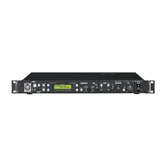
REMOTE CONTROL UNIT
RM-HP250AU
RM-HP250DE
TALLY
CALL
INTERCOM
LEVEL
Thank you for purchasing this JVC product. Before operating this
device, please read the instructions carefully to ensure the best
possible performance.
For Customer Use:
Enter below the Serial No. which is located on the body.
Retain this information for future reference.
Model No.
Serial No.
FULL AUTO
F1
F3
SHUTTER
BARS
F2
F4
GAIN
INSTRUCTIONS
REMOTE CONTROL UNIT RM-HP250
MENU/SHUTTER
GAIN
WHITE
MASTER BLACK
PAINT
AUTO
STEP
W.BAL
HIGH
B
SHUTTER
VARIABLE
MID
A
PUSH-ON
PUSH-ON
R
B
MENU
LOW
PRESET
DOWN
UP
DOWN
UP
Introduction
Connection
Preparations and
Main Functions
Camera
Adjustments
Menu Operation
General
IRIS
POWER
AUTO
MANU
CLOSE
OPEN
LST0610-001A
Advertisement
Table of Contents

Related Manuals for JVC RM-HP250DE


Summary of Contents for JVC RM-HP250DE
- Page 1 FULL AUTO BARS INTERCOM LEVEL Thank you for purchasing this JVC product. Before operating this device, please read the instructions carefully to ensure the best possible performance. For Customer Use: Enter below the Serial No. which is located on the body.
-
Page 2: Important Safeguards
Important Safeguards Read all of these instructions. Save these instructions for later use. All warnings on the product and in the operating instructions should be adhered to. Unplug this appliance system from the wall outlet before cleaning. Do not use liquid cleaners or aerosol cleaners. - Page 3 Operation of this equipment in a residential area is likely to cause harmful interference in which case the user will be required to correct the interference at his own expense. CAUTION: CHANGES OR MODIFICATIONS NOT APPROVED BY JVC COULD VOID USER’S AUTHORITY TO OPERATE THE EQUIPMENT. NOTE: The rating plate (serial number plate) is on this unit.
-
Page 4: Power System
In such case, please keep the apparatus away from the sources of the disturbance. WARNING–THIS APPARATUS Changes or modifications not approved by JVC could void the user's authority to operate the equipment. This unit is designed for professional use only. -
Page 5: Information For Users On Disposal Of Old Equipment
Penalties may be applicable for incorrect disposal of this waste, in accordance with national legislation. Union. (Business users) If you wish to dispose of this product, please visit our web page www.jvc-europe.com to obtain informa- tion about the take-back of the product. [Other Countries outside the European Union] If you wish to dispose of this product, please do so in accordance with applicable national legislation or other rules in your country for the treatment of old electrical and electronic equipment. - Page 6 Safety Precautions (continued) Place of storage and use Avoid storing or using the unit in the following places. Failure to do so may lead to malfunction or breakdown. • Extremely hot or cold places beyond the allowable tem- perature for operation (-5˚C to 40˚C) •...
- Page 7 Gerät in solchen Fällen in größerer Entfernung zur Störquelle auf. SPANNUNGSVERSORGUNG Anschluss am Netz Die Betriebsspannung für dieses Gerät beträgt AC230 V, 50 Hz (RM-HP250DE) ACHTUNG: UM DER GEFAHR VON BRÄNDEN UND ELEKTRISCHEN SCHLÄGEN VORZUBEUGEN, DARF DIESES GERÄT WEDER DEM REGEN NOCH HOHER FEUCHTIGKEIT AUSGESETZT WERDEN.
- Page 8 Union gültig. ausgesprochen werden. (Geschäftskunden) Wenn Sie dieses Produkt entsorgen möchten, besuchen Sie bitte unsere Webseite www.jvc-europe.com, um Informationen zur Rücknahme des Produkts zu erhalten. [Andere Länder außerhalb der Europäischen Union] Wenn Sie dieses Produkt entsorgen möchten, halten Sie sich dabei bitte an die entsprechenden Landesgesetze und andere Regelungen in Ihrem Land zur Behandlung elektrischer und elektronischer Geräte.
-
Page 9: Wichtige Sicherheitshinweise
WICHTIGE SICHERHEITSHINWEISE Alle Warnungen auf dem Produkt sowie in der Betriebsanleitung sind unbedingt zu beachten. Ziehen Sie den Netzstecker dieses Systems aus der Steckdose, bevor Sie das Gerät reinigen. Benutzen Sie keine Flüssigreiniger und keine Sprühreiniger. Verwenden Sie zum Reinigen lediglich ein leicht angefeuchtetes Tuch. - Page 10 Sicherheitsvorkehrungen (Fortsetzung) ACHTUNG 1) Nehmen Sie nicht die Frontabdeckung ab. 2) Falls sich die Frontabdeckung lösen sollte, setzen Sie sie sofort wieder auf. Lager- und Verwendungsort: Vermeiden Sie, den Gerät an folgenden Plätzen zu lagern oder zu verwenden. Eine Missachtung kann zu einem Fehler oder einer Störung führen. •...
-
Page 11: Technische Daten
2) Befestigen Sie diese mit M5-Schrauben am Rack. Diese Schrauben sind im Lieferumfang des RM-HP250DE enthalten. Achtung • Stellen Sie keinerlei Gegenstände auf den RM-HP250DE, wenn dieser in einem Rack montiert ist. Dies kann durch Ungleichgewicht zum Herunterfallen des Geräten führen und Verletzungen oder Schäden verursachen. -
Page 12: Table Of Contents
Introduction Thank you for purchasing this JVC product. Before operating this unit, please read the instructions care- fully to ensure the best possible performance. These instructions are for RM-HP250AU/RM-HP250DE. Contents Safety Precautions Introduction Features ... 2 Precautions for Proper Use ... 3 Controls, Connectors and Indicators ... -
Page 13: Precautions For Proper Use
Precautions for Proper Use To prolong the service life of the RM-HP250, do not use it or store it in the following places. A place subject to extremely high or low temperatures. A place subject to excessive vibration. A place subject to excessive dust. A place subject to high humidity. -
Page 14: Controls, Connectors And Indicators
Introduction Controls, Connectors and Indicators Front panel 1 2 3 4 TALLY CALL FULL AUTO BARS INTERCOM LEVEL Intercom connector Connect the intercom headset to this connector. REF. : “Intercom” on page 14. [INTERCOM LEVEL] control Use this knob to adjust the intercom earphone volume. [TALLY] lamp This lamp lights when a signal is input to the TALLY termi- nals... - Page 15 Controls, Connectors and Indicators (continued) [GAIN - VARIABLE] control with ON/OFF button *2,*3 When the button is pressed, the VARIABLE GAIN mode is switched ON and OFF alternately. The GAIN light is turned on when the VARIABLE GAIN mode is ON. When the GAIN mode is set to VARIABLE, the GAIN value can be varied from 0.1 dB (or 1.0 dB) to 18 dB in 0.1 dB (or 1.0 dB) steps.
-
Page 16: Rear Panel
Controls, Connectors and Indicators (continued) Rear panel RM-HP250AU Rear Panel TALLY INTERCOM AC ` IN AC120V 60Hz RM-HP250DE Rear Panel TALLY INTERCOM AC ` IN 230V ` 50Hz [AC ` IN] connector Connect this socket to a commercial power supply outlet using the power cord provided. - Page 17 [HD/SD SDI OUTPUT] connectors. The specification varies depending on the model. RM-HP250DE : 1 input, 2 outputs NOTE Transferred signals cannot be output via the camera cable from the HD/SD SDI output connector on RM- HP250DE.
-
Page 18: Connection
AUDIO LEVEL CH-1 CH-2 POWER GY-HD250/GY-HD251 + KA-HD250U RM-HP250AU AC ` IN AC120V 60Hz To power supply When the RM-HP250DE is connected to a camera. View Finder VF-P400 VF BRIGHT USER 1 USER 2 USER 3 ND FILTER MENU STATUS WHT.BAL... -
Page 19: Example Of Connection With 2 Units
Example of Connection with 2 Units Standard connection of RM-HP250AU (Connection of 2 units) View Finder VF-P400 VF BRIGHT USER 1 USER 2 USER 3 ND FILTER MENU STATUS WHT.BAL AUTO AUTO AUDIO CH-1 LEVEL CH-2 POWER GY-HD250/GY-HD251 + KA-HD250U RM-HP250AU TALLY AC ` IN AC120V 60Hz... - Page 20 DT109 (Beyerdynamic) Coaxial cable Camera cable VC-P110 If more than three RM-HP250DE units are connected, the intercom volume level will be reduced. *1 When connect the remote control unit cable to the REMOTE connector, please be care full to the following points.
-
Page 21: Rack Mounting
Rack Mounting Mount this unit to the EIA rack. Rack mount bracket Turning the Power ON REMOTE CONTROL UNIT RM-HP250 POWER WHITE MASTER BLACK IRIS PAINT AUTO W.BAL AUTO MANU PRESET CLOSE OPEN POWER switch NOTE When an item is controllable from both the RM-HP250 and the camera, the control from the camera is defeated. Functions not available on the camera cannot be controlled from this unit. -
Page 22: Preparations And Main Functions Camera Cable Length Setup
Preparations and Main Functions Camera Cable Length Setup Cable length setup is required when a camera is connected to the RM-HP250 for the first time or when the camera cable length is changed. The cable length setup value is stored in the memory inside the RM-HP250 and is held even after it is turned OFF. -
Page 23: Adjustments For Genlock Operation
Adjustments for Genlock Operation Genlocking is required for a system, which uses an SEG (special effects generator) as the main signal source. REF. : “Example of Connection with 2 Units” on page 9. NOTE The following adjustments can be made more accurately when using a vectorscope and waveform monitor. Be sure to use an underscanned video monitor. -
Page 24: Intercom
(The modifications and adjustments will be carried out with charge.) The factory settings vary depending on the model. RM-HP250AU : RTS system. *1 RM-HP250DE : 2-wire system, which uses the H and C AUX VIDEO INPUT GENLOCK INPUT An intercom connector is provided on the front panel of the RM-HP250. -
Page 25: Function Keys
Function Keys Up to four of the functions listed at the bottom of this page can be assigned to function keys F1 to F4 so that each function can be switched on or off by pressing the corresponding key. (For the assignment of functions: REF. Items 5H to 5K, “FUNC1” to “FUNC4” in the OPERATION MENU description on page 25.) <Example of factory setting>... -
Page 26: Camera Adjustments Shutter Speed Adjustment
Camera Adjustments Shutter Speed Adjustment Turning the SHUTTER control can vary the shutter speed of the camera. The LCD display shows the shutter speed during the adjustment operation. SHUTTER light FULL AUTO SHUTTER 1/1000 BARS GAIN SHUTTER control NOTE When the FAS (Full Auto Shooting) is ON, the shutter speed becomes EEI. -
Page 27: Gain Adjustment
Gain Adjustment When the illumination of the object is insufficient, the electrical gain can be boosted as described below. GAIN light MENU/SHUTTER SHUTTER SHUTTER VARIABLE PUSH-ON PUSH-ON MENU GAIN DOWN DOWN GAIN display GAIN control NOTE When the FULL AUTO or ALC+EEI is ON, the gain be- comes ALC. -
Page 28: White Balance Adjustment
Camera Adjustments White Balance Adjustment Since color temperature varies depending on the light source, the white balance should be ad- justed whenever the main light source illuminating the object being shot changes. AUTO WHITE button REMOTE CONTROL UNIT RM-HP250 U/SHUTTER GAIN PAINT WHITE... -
Page 29: Menu Operation Flow Of Menus
Menu Operation Flow of Menus The menus displayed on the RM-HP250 are provided in the form shown below. Category Item 1: GENLOCK Page 21) 1A: SD H PHASE 1B: HD H PHASE 1C: SC COARSE 1D: SC FINE 1Z: BACK 2: CABLE Page 21) 2A: LENGTH... -
Page 30: Menu Setup Method
Menu Operation Menu Setup Method Each menu is displayed on the LCD display and can be set up using the MENU button and the control knob. The values set in the “4: PROCESS” and “5: OPERATION” menus can be saved in files A, B, C and D. <Example of changing the camera cable length from 20 m to 100 m>... -
Page 31: Genlock Menu
GENLOCK Menu This menu is used to set the camera cable length to the length actually used. ( REF. : “Adjustments for Genlock Operation” on page 13.) Item SD H PHASE Adjustment of the Horizontal sync phase of genlocking. HD H PHASE Adjustment of the Horizontal sync phase of genlocking. -
Page 32: File Menu
Menu Operation FILE Menu The values set with the menu and applied to the RM-HP250 can be saved in four files named A, B, C and D. FULL AUTO SHUTTER 3. FILE BARS GAIN LCD display MENU button 1: GEN LOCK 2: CABLE Cursor 3: FILE... -
Page 33: Process Menu
PROCESS Menu This menu sets the functions built into the camera. NOTE Functions not available on the camera cannot be controlled from this unit. Item DETAIL ON/OFF setting of the detail enhancement function. OFF : Detail enhancement is deactivated. ON : Detail enhancement is activated. DETAIL LEVEL Adjusts the detail enhancement level. - Page 34 Menu Operation PROCESS Menu (continued) Item V.RESOLUTION Increases the vertical resolution. NORMAL : Standard value. V.MAX NOTE When the vertical resolution is increased, the sensitivity deterio- rates and bright areas of objects may appear to be colored. GAMMA ON/OFF setting of the gamma curve correction, which determines the reproduction of black.
-
Page 35: Operation Menu
OPERATION Menu This menu sets the functions built into the RM-HP250. Item SHUTTER Selects whether the front panel SHUTTER control varies the shutter speed in steps or in fine variation. STEP VARIABLE: Fine, continual variation to be used when shooting V. -
Page 36: Lcd Mode Menu
Menu Operation LCD MODE Menu This menu sets up the LCD display. Item CONTRAST Adjusts the contrast of the LCD display. BACKLIGHT Adjusts the setting of the backlight of the LCD display. OFF : Backlight is turned off. : Backlight is turned on. BACK Returns to the previous display. -
Page 37: System Reset
SYSTEM Menu continued SYSTEM RESET This menu resets the values set by the user to the initial values. FULL AUTO SHUTTER 1/1000 +9dB BARS MENU GAIN LCD display MENU button 6: LCD MODE 7: SYSTEM 7A: SYSTEM RESET 7A: SYSTEM RESET 7A: SYSTEM RESET NOW INITIALIZING JUST A MOMENT... -
Page 38: General Warning Messages
General Warning Messages To prevent operational errors, the LCD display shows one of the following warning messages when an erroneous operation is performed. Displayed Message INVALID ENTRY GAIN : LOLUX INVALID ENTRY FULL AUTO : ON INVALID ENTRY GAIN : ALC + EEI INVALID ENTRY GAIN : ALC INVALID ENTRY... -
Page 39: Operable Camera Features
HD H. PHASE SC COARSE SC FINE *1 : This function is not the standard setting. For details, please consult JVC’s authorized dealers. *2 : Changes depending on the VIDEO FORMAT. *3 : The above feature may not function depending on the version of the camera’s software. -
Page 40: Operation Of Connected Camera
General Operation of Connected Camera When RM-HP250 is connected to a camera, all features that are available on RM-HP250 can only be controlled by RM-HP250, and control of these features using the camera is disabled. Switches on the camera that are disabled, as well as disabled menu items are as follows. Standard connection of RM-HP250 (Connection of 2 units) GAIN SHUTTER(1... -
Page 41: Troubleshooting
If it is required to use the TALLY input in the contact supply mode, the setting of the internal circuitry should be changed ; consult the nearest JVC-authorized service agent. Is the STUDIO cable of KA-HD250U pulled out or loose? -
Page 42: Specifications
VBS signal: 1 Vp-p, 75 Ø or Black Burst signal: 0.43 Vp-p, 75 Ø loop-through output Y signal: 1 Vp-p, 75 Ø loop-through output VBS signal: 1 Vp-p, 75 Ø loop-through output RM-HP250DE ← ← ← 2-line system, -10 dB, 600 Ø, balanced ← ←... -
Page 43: External Dimensions
LEVEL 340 to 370 RM-HP250AU Rear Panel TALLY INTERCOM AUX VIDEO INPUT GENLOCK INPUT AC ` IN AC120V 60Hz RM-HP250DE Rear Panel TALLY INTERCOM AUX VIDEO INPUT GENLOCK INPUT AC ` IN 230V ` 50Hz RM-HP250AU REMOTE CONTROL UNIT RM-HP250... - Page 44 © 2007 Victor Company of Japan, Limited. LST0610-001A...
Need help?
Do you have a question about the RM-HP250DE and is the answer not in the manual?
Questions and answers