Table of Contents
Advertisement
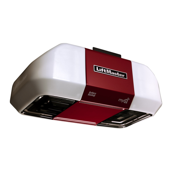
ELITE Series
Garage Door Opener
Models
• 8550 - DC Belt Drive
with Battery Backup
• 8557 - 3/4 hp
Belt Drive
FOR RESIDENTIAL USE ONLY
■ Please read this manual and the enclosed safety materials carefully!
■ Fasten the manual near the garage door after installation.
■ The door WILL NOT CLOSE unless the Protector System
aligned.
■ Periodic checks of the garage door opener are required to ensure safe operation.
■ The model number label is located on the left side panel of your garage door opener.
■ This garage door opener is ONLY compatible with MyQ
accessories.
■ DO NOT enable the Timer-to-Close feature if you are installing the garage door
opener on a one-piece door. The Timer-to-Close is to be used ONLY with
sectional doors.
NOTE: If you are installing the garage door opener on a one-piece door, visit
www.liftmaster.com for installation instructions.
.
®
is connected and properly
®
and Security✚ 2.0™
Write down the following information for
future reference:
Serial Number:
Date of Purchase:
CONTENTS
Preparation . . . . . . . . . . . . . . . .2-3
Assembly . . . . . . . . . . . . . . . . .4-5
Installation . . . . . . . . . . . . . . . 6-13
Install the Door Control . . . . . . 14-16
®
. . 17-20
Power. . . . . . . . . . . . . . . . . . 21-22
Adjustments . . . . . . . . . . . . . 23-25
Battery Backup*. . . . . . . . . . . 26-27
Operation . . . . . . . . . . . . . . . . . 28
Features . . . . . . . . . . . . . . . . . . 29
Door Control . . . . . . . . . . . . . 30-31
Remote Control . . . . . . . . . . . 32-33
To Erase the Memory . . . . . . . . . 33
To Open the Door Manually . . . . . 34
Maintenance . . . . . . . . . . . . . . . 34
Troubleshooting. . . . . . . . . . . 35-36
Accessories. . . . . . . . . . . . . . . . 37
Warranty. . . . . . . . . . . . . . . . . . 38
Repair Parts . . . . . . . . . . . . . 39-41
* If applicable
www.liftmaster.com
The Chamberlain Group, Inc.
845 Larch Avenue
Elmhurst, Illinois 60126-1196
Advertisement
Table of Contents

Related Manuals for Chamberlain 8550


Summary of Contents for Chamberlain 8550
-
Page 1: Table Of Contents
Power....21-22 Models Adjustments ... . . 23-25 • 8550 - DC Belt Drive Battery Backup*... 26-27 with Battery Backup Operation . -
Page 2: Preparation
Preparation Safety Symbol and Signal Tools Needed Check the Door Word Review 1. Disable locks and remove any ropes This garage door opener has been designed and To prevent possible SERIOUS INJURY or connected to the garage door. tested to offer safe service provided it is installed, DEATH: 2. -
Page 3: Carton Inventory
Carton Inventory SECURITY✚ 2.0 ACCESSORIES NOTE: Accessories will vary depending on the garage door opener model purchased. Depending on your specific model, other accessories may be included with your garage door opener. The instructions for these accessories will be attached to the accessory and are not included 880LM in this manual. -
Page 4: Assembly
Attach the sprocket cover over the #8x3/8" garage door opener sprocket and Washered Bolt attach with hex screws. 5/16"-18x1/2" (Mounted in the garage door opener) Model 8550 (2) Model 8557 (1) Lock Nut (Mounted in the garage door opener) Model 8557 (1) Hex Screw #8x3/8"... - Page 5 Tighten the Belt By hand, thread the spring trolley nut on the threaded shaft until it is finger tight against Insert a flathead screwdriver tip into one of the nut ring slots and brace it firmly against the trolley. the trolley. Do not use any tools. (To motor unit) Nut ring Spring Trolley Nut...
-
Page 6: Important Installation Instructions
Installation IMPORTANT INSTALLATION INSTRUCTIONS WARNING To reduce the risk of SEVERE INJURY or DEATH: 9. Install wall-mounted garage door control: 1. READ AND FOLLOW ALL INSTALLATION WARNINGS AND INSTRUCTIONS. 2. Install garage door opener ONLY on properly balanced and lubricated garage door. An •... -
Page 7: Determine The Header Bracket Location
Determine the header bracket location NOTE: If you are installing the garage door opener on a one-piece door, visit www.liftmaster.com for OPTIONAL Unfinished installation instructions. CEILING Ceiling MOUNT FOR Close the door and mark the inside vertical centerline of the garage door. HEADER Header Wall To prevent possible SERIOUS INJURY or... -
Page 8: Install The Header Bracket
Installation 2 Install the Header Bracket You can attach the header bracket either to the OPTION A WALL INSTALLATION (Header Wall) wall above the garage door, or to the ceiling. Vertical 2.1A Centerline of Center the bracket on the vertical Follow the instructions which will work best for Wall Mount Garage Door... -
Page 9: Attach The Rail To The Header Bracket
Attach the rail to the header bracket HARDWARE Align the rail with the header bracket. Ring Insert the clevis pin through the holes in Fastener the header bracket and rail. Secure with the ring fastener. Clevis Pin NOTE: Use the packing material as a 5/16"... -
Page 10: Hardware
Installation Hang the garage door opener FIGURE 2 FIGURE 1 Hanging your garage door opener will vary depending on your Unfinished Ceiling Finished Ceiling garage. Two representative installations are shown. Yours may be different. Hanging brackets should be angled (Figure 1) to Not Provided provide rigid support. -
Page 11: Attach The Emergency Release Rope And Handle
Install the light bulbs Pull on the top center of the light lens and rotate the light lens down. Insert an A19 incandescent (100W maximum) or To prevent possible OVERHEATING of the end panel or light socket: compact fluorescent (26W, 100W equivalent) light •... -
Page 12: Installation
Installation FIGURE 1 A horizontal and vertical reinforcement is needed for lightweight garage doors Install the door bracket (fi berglass, aluminum, steel, doors with glass panel, etc.) (not provided). A horizontal reinforcement brace should be long enough to be secured to two or three vertical supports. -
Page 13: Clevis Pin 5/16" X 2-3/4
9 Connect the door arm to the trolley IMPORTANT: The groove on the straight door arm MUST face away from the curved door arm. Attach the straight door arm to the outer Close the door. Disconnect the trolley by Attach the curved door arm to the door CORRECT trolley using the clevis pin. -
Page 14: Install The Door Control
Install the Door Control Install the door control INTRODUCTION HARDWARE ® Compatible with MyQ and Security+ 2.0™ accessories, see page 37. Your garage door Screw To prevent possible SERIOUS INJURY or DEATH from electrocution: opener is compatible with up to 2 Smart Control 6ABx1"... - Page 15 Install the Door Control Position the bottom hole of the door Lift the push bar up and mark the top hole. Remove the door control from the wall Position the bottom hole of the control over the screw and slide and drill a 5/32 inch (4 mm) hole for door control over the screw and down into place.
-
Page 16: Attach The Warning Labels
Install the Door Control Attach the warning labels Attach the entrapment warning label on the wall near the door control with tacks or staples. Attach the manual release/safety reverse test label in a visible location on the inside of the garage door. -
Page 17: Install The Protector System
® Install the Protector System Introduction IMPORTANT INFORMATION ABOUT THE SAFETY REVERSING SENSORS The safety reversing sensors must be connected and aligned correctly before the garage door opener will move in the down direction. The sending sensor (with an amber LED) transmits an invisible light beam to the receiving sensor (with a green LED). If an obstruction breaks the light beam while the door is closing, the door will stop and reverse to the full open position, and the garage door opener lights will flash 10 times. -
Page 18: Carriage Bolt 1/4"-20X1/2
® Install the Protector System Install the Safety Reversing Sensors The safety reversing sensors can be attached to the door track, the wall, or the floor. If the door track will not support the sensor bracket a wall installation is recommended. Choose one of the following installations. OPTION A DOOR TRACK INSTALLATION HARDWARE... - Page 19 ® Install the Protector System 1 Install the Safety Reversing Sensors OPTION C FLOOR INSTALLATION Use an extension bracket (not provided) or wood block to raise the sensor bracket if needed. 1.1C Carefully measure the position of both 1.3C 1.4C Slide the carriage bolt into the slot on Insert the bolt through the hole in the sensor 1.2C...
- Page 20 ® Install the Protector System OPTION B PRE-WIRED INSTALLATION 2.1B 2.2B 2.3B Cut the end of the safety Separate the safety reversing sensor wires and strip 7/16 inch (11 mm) of Connect the pre-installed wires to the sensor wires with wire nuts reversing sensor wire, making insulation from each end.
-
Page 21: Power
Properly secure wire under plastic ties so that wire does not come in contact with moving parts. Ground Tab 1.10B Reinstall the cover. DO NOT run garage door opener at this time. Green Wiring through a terminal block (8550 models manufactured after April 12, 2013 and all 8557 models): Black Ground 1.1B Wire Remove the motor unit cover screws and set the cover aside. - Page 22 Power Ensure the Safety Reversing Sensors are aligned The door will not close if the sensors Check to make sure the LEDs in both sensors are glowing steadily. The LEDs in both sensors will glow steadily if they have not been installed and aligned are aligned and wired correctly.
-
Page 23: Adjustments
Adjustments INTRODUCTION Your garage door opener is designed with electronic controls to make setup and adjustments easy. The adjustments allow you Without a properly installed safety reversal to program where the door will stop in the system, persons (particularly small children) open (UP) and close (DOWN) position. - Page 24 Adjustments Program the Travel Without a properly installed safety reversal system, persons (particularly small children) could be SERIOUSLY INJURED or KILLED by a closing garage door. • Incorrect adjustment of garage door travel limits will interfere with proper operation of safety reversal system. •...
-
Page 25: Test The Safety Reversal System
Adjustments Test the Safety Reversal System With the door fully open, place a 1-1/2 Press the remote control push button to If the door stops and does not reverse on inch (3.8 cm) board (or a 2x4 laid flat) on close the door. -
Page 26: Battery Backup
Battery Backup* Install the battery Unplug the garage door opener. To reduce the risk of FIRE or INJURY to persons: Open the light lens on the right side panel of the garage door opener. Use a Phillips • Disconnect ALL electric and battery power head screwdriver to remove the battery cover on the garage door opener. - Page 27 Battery Backup* Charge the Battery Battery Status LED NOTE: The Battery Status LED is most visible with the garage door opener light off. Battery does not GREEN LED: have to be fully charged to operate the garage The battery charges when the garage door opener All systems are normal.
-
Page 28: Operation
Operation IMPORTANT SAFETY INSTRUCTIONS WARNING To reduce the risk of SEVERE INJURY or DEATH: 1. READ AND FOLLOW ALL WARNINGS AND INSTRUCTIONS. 10. Safety reversal system MUST be tested every month. Garage door MUST reverse on 2. ALWAYS keep remote controls out of reach of children. NEVER permit children to operate or contact with 1-1/2"... -
Page 29: Features
Features Your garage door opener is equipped with features to provide you with greater control over your ENERGY CONSERVATION garage door operation. For energy efficiency the garage door opener will enter sleep mode when the door is fully closed. The Alert2Close sleep mode shuts the garage door opener down until activated. -
Page 30: Door Control
Door Control USING THE DOOR CONTROL The following features are accessible through the screen using the navigation buttons: LEARN A DEVICE SYNCHRONIZE THE DOOR CONTROL ® Any compatible remote controls, wireless keyless entry, or MyQ accessories can be programmed to To synchronize the door control to the garage door opener, press the push bar until the garage door the garage door opener by accessing the menu and using the navigation buttons. -
Page 31: Door Control Hardware
Door Control Smart Control Panel Setup The features on the door control can be programmed through a series of menus on the screen and the navigation buttons. Refer to the descriptions below. SCREEN FEATURES SETTINGS SERVICE Press the navigation button below "MENU" to view The main screen displays the time, Press the navigation button below the down arrow Press and hold the second navigation button, then... -
Page 32: Remote Control
Remote Control Your remote control has been programmed at the factory to operate with your garage door opener. Older LiftMaster remote controls are NOT compatible, see page 37 for compatible accessories. Programming can be done through the door control or the learn button the garage door opener. To program ®... -
Page 33: To Erase The Memory
Remote Control Using a safety pin or paper clip, press the Press and release the Learn button on the Press and release the remote control button you want to use... program button until the LEDs on the front of garage door opener. The Learn LED will light. Check to see if the garage door opener light bulb blinks. -
Page 34: To Open The Door Manually
To Open the Door Manually DISCONNECT THE TROLLEY The door should be fully closed if possible. Pull down on the emergency release handle. To prevent possible SERIOUS INJURY or DEATH from a falling garage door: RECONNECT THE TROLLEY • If possible, use emergency release handle to disengage trolley ONLY when garage door is The lockout feature prevents the trolley from reconnecting automatically. -
Page 35: Troubleshooting
Troubleshooting Diagnostic Chart Your garage door opener is programmed with self-diagnostic capabilities. The UP and DOWN arrows on the garage door opener flash the diagnostic codes. DIAGNOSTIC CODE SYMPTOM SOLUTION Up Arrow Down Arrow Flash(es) Flash(es) The garage door opener will not close and the light Safety sensors are not installed, connected or wires may be cut. - Page 36 Troubleshooting DIAGNOSTIC CODE SYMPTOM SOLUTION Up Arrow Down Arrow Flash(es) Flash(es) Door is moving stops and or reverses. Manually open and close the door. Check for binding or obstructions, such as a broken spring or door lock, correct as needed. If the door is binding or sticking contact a trained door systems technician. If door is not binding or sticking attempt to reprogram travel (refer to page 24 ).
-
Page 37: Accessories
Accessories ® ® 828LM LiftMaster Internet Gateway: 829LM Garage and Gate Monitor: 895MAX 3-Button Premium 880LM Smart Control Panel MAX Remote Control: Internet enabled accessory Monitor open/closed status for up to Displays temperature, time and system ® ® which connects to the computer 4 MyQ compatible garage door Compatible with LiftMaster... -
Page 38: Warranty
Warranty ® LIFTMASTER FIVE YEAR LIMITED WARRANTY LIFETIME MOTOR AND BELT LIMITED WARRANTY ONE YEAR LIMITED WARRANTY FOR THE BATTERY BACKUP SYSTEM The Chamberlain Group, Inc. (“Seller”) warrants to the first retail purchaser of this product, for the residence in which this product is originally installed, that it is free from defects in materials and/or workmanship for a period of five years from the date of purchase, except that the motor and belt are warranted to be free from defects in materials and/or workmanship for the lifetime of the product while you own your residence, and the Battery Backup System is warranted to be free from defects in materials and/or workmanship for a period of one year from the date of purchase. -
Page 39: Repair Parts
Repair Parts Rail Assembly Parts Installation Parts Description Part Number Description Part Number Belt - for 7 foot door 41A5434-11 Curved Door Arm 178B35 Belt - for 8 foot door 41A5434-13 Door Bracket with Clevis 41A5047-1 Pin and Fastener Belt - for 10 foot door 41A5434-14 Emergency Release Rope 41A2828... - Page 40 Repair Parts Description Part Number Sprocket and Sprocket Cover with 41C589-2 Garage Door Opener Parts - MODEL 8550 Screws End Panel with battery cover and light 41D217 socket Light Lens 41A7562 Light Socket 41C279 Transformer 41A7635 Cover 41A7619-2 Motor and Travel Module...
- Page 41 Repair Parts DESCRIPTION Part Number Cover with screws 41A4371 Garage Door Opener Parts - MODEL 8557 Gear and sprocket 41A4885-5 Drive and Worm Gear 41A2817 Line Cord 41B4245-1 End panel 041A7756 Light Socket 41C279 Light Lens 41A7562 Capacitor 30B652 Gear Case 41A5532 Terminal Block 41A3150...
Need help?
Do you have a question about the 8550 and is the answer not in the manual?
Questions and answers