Table of Contents
Advertisement
Parts & Maintenance
Manual
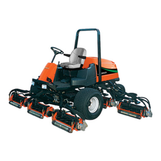
Lightweight Fairway Mower
67868 – LF 3400
67869 – LF 3400
67866 – LF 3800
67867 – LF 3800
67889 – LF 3400
67915 – LF 4675
67916 – LF 4677
67936 – LF 3800
GB
, Kubota V1305-E, 5 Gang, 2WD
™
, Kubota V1305-E, 5 Gang, 4WD
™
, Kubota V1505-E, 5 Gang, 2WD
™
, Kubota V1505-E, 5 Gang, 4WD
™
Turbo, Kubota V1505-TE, 5 Gang, 4WD
™
Turbo, Kubota V1505-TE, 7 Gang, 4WD
™
Turbo, Kubota V1505-TE, 7 Gang, 4WD
™
Turbo, Kubota V1505-TE, 5 Gang, 4WD
™
4100741-Rev B
6
5
9
1 1
1 6
1 3
1 5
7
8
1 8
1 7
1 - I N C L U D E S I T E M S 3 - 1 6
1 9
3
1 0
4
Advertisement
Chapters
Table of Contents

Subscribe to Our Youtube Channel
Related Manuals for Jacobsen 67868


Summary of Contents for Jacobsen 67868
- Page 1 1 - I N C L U D E S I T E M S 3 - 1 6 Parts & Maintenance Manual Lightweight Fairway Mower 67868 – LF 3400 , Kubota V1305-E, 5 Gang, 2WD ™ 67869 – LF 3400 , Kubota V1305-E, 5 Gang, 4WD ™...
-
Page 2: Table Of Contents
To Order Parts 1. Write your full name and complete address on the 5. Send or bring the order to an authorized Textron Turf order. Care And Specialty Products Dealer. 2. Explain where and how to make shipment. 6. Inspect all shipments on receipt. If any parts are dam- aged or missing, file a claim with the carrier before 3. -
Page 3: Service Parts
Suggested Stocking Guide To Keep your Equipment fully operational and productive, maintain a stock of the more commonly used maintenance items. We have included part numbers for additional support materials and training aids. A more complete listing of accessories and attachments can be found in the Specifications Section Service Parts Qty. -
Page 4: Safety
SAFETY SAFETY OPERATING SAFETY ______________________________________________________ WARNING EQUIPMENT OPERATED IMPROPERLY OR BY UNTRAINED PERSONNEL CAN BE DANGEROUS. Familiarize yourself with the location and proper use of all controls. Inexperienced operator’s should receive instruction from someone familiar with the equipment before being allowed to operate the machine. Safety is dependent upon the awareness, concern and Never disconnect or bypass any switch. -
Page 5: Important Safety Notes
SAFETY IMPORTANT SAFETY NOTES ________________________________________________ This safety alert symbol is used to alert you to potential hazards. DANGER WILL result in death or serious injury. - Indicates an imminently hazardous situation which, if not avoided, WARNING COULD result in death or serious injury. - Indicates a potentially hazardous situation which, if not avoided, CAUTION MAY result in minor or moderate injury and... -
Page 6: Specifications
67867......LF 3800, 5 Gang 4WD, uses 7” TEXTRON TURF CARE AND SPECIALTY PRODUCTS (178 mm) diameter reel RACINE, WI MADE IN U.S.A. 67868......LF 3400, 5 Gang 2WD, uses 5” 67866 1601 (127 mm) diameter reel 67869......LF 3400, 5 Gang 4WD, uses 5”... -
Page 7: V1505-Te Engine
SPECIFICATIONS V1505-TE ENGINE _________________________________________________________ Make........Kubota Governor Setting: Model.......V-1505TE Diesel, 4 cycle, Liquid High Idle....3150 rpm Cooled Low Idle..... 1200 rpm Horsepower .....44.2 Hp (33.0 Kw) @ 3000 rpm Lubrication: Capacity ....5.5 U.S. qts. (5.2 liter) Displacement....91.4 in. (1498 cm Type ...... -
Page 8: Cutting Units
SPECIFICATIONS CUTTING UNITS___________________________________________________________ LF 3400, LF3400 Turbo, LF 4675 LF 3800, LF 4677, LF 3800 Turbo Overall cutting Width: Overall cutting Width: 5 Gang ...... 100 in. (2.54 m) 5 Gang...... 100 in. (2.54 m) 7 Gang ...... 139 in. (3.53 m) 7 Gang...... -
Page 9: Adjustments
ADJUSTMENTS ADJUSTMENTS GENERAL ________________________________________________________________ cannot be made, contact an authorized Textron Turf WARNING Care And Specialty Products Dealer. Replace, do not adjust, worn or damaged components. To prevent injury, lower implements to the ground, disengage all drives, engage parking brake, stop engine Do not wear jewelry or loose fitting clothing when and remove key from ignition switch before making any making adjustments or repairs. -
Page 10: Bedknife Adjustment
ADJUSTMENTS BEDKNIFE ADJUSTMENT ___________________________________________________ Read Section 3.2 before making the adjustment. Note: Avoid excessive tightening or damage may occur to bedknife and reel blades. Reels must turn freely. CAUTION To prevent personal injury and damage to the cutting edges, handle the reel with extreme care Start adjustment at leading end of reel, followed by the trailing end. -
Page 11: Flash Attach
ADJUSTMENTS FLASH ATTACH ___________________________________________________________ Installing Cutting units Carefully raise arm until cutting unit can be removed. Place each cutting unit in front of its respective lift arm. Raise lift arm and position cutting unit so that yoke (T) is in line with swivel housing (S). Carefully lower arm onto yoke. -
Page 12: Mow Speed
ADJUSTMENTS MOW SPEED _____________________________________________________________ Cutting quality is better at speeds well below the transport speed of the tractor. An initial mow speed of five to six mph is set at the factory and should be satisfactory for most cutting conditions. Local turf conditions however may respond better to a different speed. -
Page 13: Neutral Adjustment
ADJUSTMENTS 3.10 NEUTRAL ADJUSTMENT ___________________________________________________ Neutral adjustment can only be made at the drive pump. Connect traction linkage. When connecting linkage at traction pedal make sure pointer on traction pedal The neutral adjustment is preset at the factory on all new bracket is centered over neutral switch (M -Figure 3K). -
Page 14: Front Reel Limit Switch
ADJUSTMENTS 3.12 FRONT REEL LIMIT SWITCH ________________________________________________ The front left and right lift arms are equipped with reed Start engine and check that reels turn off when raised. switches which signal the controller to turn off the reels.The Note: The reed switches set the point where the reels switches are mounted to the tractor frame directly behind the turn off, not how high they will raise. -
Page 15: Steering Toe-In
ADJUSTMENTS 3.14 STEERING TOE-IN _________________________________________________________ Turn wheels to straight ahead position. Loosen jam nuts (J) on both sides of tie rod (M). Turn tie rod (M) to provide proper toe-in. Toe-in must not exceed +1/16” (1.5 mm) (K). Retighten jam nuts. After adjusting tie rod, adjust steering cylinder by threading the rod (N in or out of ball joint so spindle arm (L) clears the stop on the axle by 1/32 to 3/32in. -
Page 16: Torque Specification
ADJUSTMENTS 3.15 TORQUE SPECIFICATION __________________________________________________ CAUTION All torque values included in these charts are approximate and are for reference only. Use of these torque values is at your sole risk. Textron Turf Care And Specialty Products is not responsible for any loss, claim, or damage arising from the use of these charts. -
Page 17: Maintenance
MAINTENANCE MAINTENANCE GENERAL ________________________________________________________________ Keep all moving parts properly adjusted and lubri- WARNING cated. Replace worn or damaged parts before operating Before you clean, adjust, or repair this equipment, the machine. disengage all drives, lower implements to the ground, engage parking brake, stop engine and remove key from Keep all fluids at their proper levels. -
Page 18: Air Filter
MAINTENANCE AIR FILTER_______________________________________________________________ Check the service indicator daily. If red band appears in the Reassemble cap making sure it seals completely window (B) replace the element. around the filter housing. Dust evacuator must be facing down. Do not remove the element for inspection or cleaning. Check all hoses and air ducts. -
Page 19: Battery
MAINTENANCE BATTERY ________________________________________________________________ Make absolutely certain the ignition switch is “Off” and the When installing the battery, always assemble the RED, positive (+) battery cable first and the ground, BLACK, key has been removed before servicing the battery. negative (-) cable last. When removing the battery, always remove the ground, CAUTION BLACK, negative (-) cable first and the RED, positive... -
Page 20: Muffler And Exhaust
MAINTENANCE 4.10 MUFFLER AND EXHAUST___________________________________________________ To protect from carbon monoxide poisoning, inspect the WARNING complete exhaust system regularly and always replace a defective muffler. Exhaust fumes contain carbon monoxide that is toxic and can be fatal when inhaled. If you notice a change in the color or sound of the exhaust, stop the engine immediately. -
Page 21: Hydraulic Filters
MAINTENANCE 4.13 HYDRAULIC FILTERS ______________________________________________________ The hydraulic system is protected by two 10 micron filters; a Check hydraulic oil level in reservoir and fill to full mark charge filter (B) and return line filter (A). Flow though the on dipstick. filters is monitored during operation. -
Page 22: Radiator
MAINTENANCE 4.15 RADIATOR _______________________________________________________________ Use a blow gun to clean the radiator and oil cooler fins. WARNING Note: A sliding panel located under the frame can be loosened and pulled back to allow dirt and debris to fall To prevent serious bodily injury from hot coolant or though frame. -
Page 23: Wheel Mounting Procedure
MAINTENANCE 4.18 WHEEL MOUNTING PROCEDURE ____________________________________________ Remove dirt, grease and oil from stud thread. Do not lubricate threads. WARNING Position wheel on hub and inspect to insure full contact Make sure the tractor is parked on a solid and level between mounting surface of wheel and hub or brake surface. -
Page 24: Reel Backlapping
MAINTENANCE 4.20 REEL BACKLAPPING ______________________________________________________ WARNING To prevent severe injury, keep hands, feet and clothing away from rotating reels. Carbon monoxide in the exhaust fumes can be fatal when inhaled, never operate the engine without proper ventilation Check the reel and bedknife to determine if backlapping or grinding will restore the cutting edge. -
Page 25: Storage
MAINTENANCE 4.21 STORAGE ________________________________________________________________ General After Storage Wash the tractor thoroughly and lubricate. Repair and Check and reinstall battery paint damaged or exposed metal. Check or service fuel filter and air cleaner. Inspect the tractor, tighten all hardware, replace worn Check the radiator coolant level. -
Page 26: Troubleshooting
TROUBLESHOOTING TROUBLESHOOTING GENERAL________________________________________________________________ The troubleshootijng chart below lists basic problems that may occur during start-up and operation. For more detailed information regarding the hydraulic and electrical systems contact your area Textron Turf Care And Specialty Products Dealer. Symptoms Possible Causes Action Engine will not start. -
Page 27: Controller Lamps
TROUBLESHOOTING CONTROLLER LAMPS _____________________________________________________ The controller is a solid state device that monitors and indicates an active circuit and will turn an input lamp on, an controls electrical functions. The controller receives input open switch an inactive circuit and will turn a lamp off. signals from various switches and sensors throughout the Outputs are active when their lights are on. -
Page 28: Electrical Circuits
TROUBLESHOOTING ELECTRICAL CIRCUITS ____________________________________________________ When troubleshooting the machine using the controller always check that Program Active lamps (1, 2 and 3 - 5 Gang)(2 and 3 - 7 Gang) are on. These indicate that the controller has power and the program is active. Note: The controller requires a minimum of six volts to operate. -
Page 29: Maintenance & Lubrication Charts
MAINTENANCE & LUBRICATION CHARTS MAINTENANCE & LUBRICATION CHARTS GENERAL ________________________________________________________________ Lubricate with grease that meets or exceeds NLGI WARNING Grade 2 LB specifications. Apply grease with a manual grease gun and fill slowly until grease begins to seep Before you clean, adjust, or repair this equipment, out. -
Page 30: Lubrication Chart
MAINTENANCE & LUBRICATION CHARTS LUBRICATION CHART _____________________________________________________ Grease points same for all reels Grease Fittings F1 - 50 Hours (Every Week) Swivel Housing Lift Arm Lift Cylinders Lift Arm Pivot Brake Pedal Pivot Traction Pedal Pivot Ball Joint Steering Pivot Steering Cylinder 10 Axle Pivot F2 - 100 Hours... -
Page 31: Parts Catalog 7.1 Table Of Contents
PARTS CATALOG PARTS CATALOG TABLE OF CONTENTS _____________________________________________________ 1.1 ..Decals ..............32 33.1..Front Reel Hydraulics ........... 79 2.1 ..Hood ............... 34 34.1..Rear Reel Hydraulics ..........80 3.1 ..Seat Pan ..............36 35.1..Rear Reel Hydraulics ..........81 4.1 ..Instrument Panel ........... 38 36.1..Lift Arms.............. -
Page 32: Decals
LF 3400 / LF 3800 Serial No. All 1.1 Decals LF-4675 / 4677 LF-3400 / 3800 WARNING WARNING 1. Read operators manual. 1. Read operators manual. Do not allow untrained Do not allow untrained operators to use machine. operators to use machine. 2. - Page 33 Decal, Instrument Panel LF 3400 / 3800 3008327 Decal, 4WD 4WD Only 3002363 Decal, Backlap Switch Located on Controller Housing 3007505 Decal, Jacobsen 3007514 Decal, Textron 3007750 Decal, Left Side Blue Stripe 3007751 Decal, Right Side Blue Stripe > 2812268...
-
Page 34: Hood
LF 3400 / LF 3800 Serial No. All 2.1 Hood LF34-1... - Page 35 LF 4675 / LF 4677 Item Part No. Qty. Description Serial Numbers/Notes 1003527 Hood Assembly, LF 3400/3800 Includes Items 16 ~ 20 on Illustration 1.1 1004981 Hood Assembly, LF 4675/4677 Includes Items 16 ~ 20 on Illustration 1.1 3007549 • Foam, Front 3007550 •...
-
Page 36: Seat Pan
LF 3400 / LF 3800 Serial No. All 3.1 Seat Pan 26 / 27... - Page 37 LF 4675 / LF 4677 Item Part No. Qty. Description Serial Numbers/Notes 1004279 Floorpan 3009292 Seat Pan 3006909 Support, Right Seat 3006910 Support, Left Seat 3009995 Adjuster, Latching 3006988 Adjuster, Slave 400258 Screw, 3/8-16 x 3/4” Hex Head 441602 Carriage Bolt, 5/16-18 x 3/4” 445795 Nut, 5/16-18 Spiralock Flange 446142...
-
Page 38: Instrument Panel
LF 3400 / LF 3800 Serial No. All 4.1 Instrument Panel 5 Gang Units (LF 3400, LF 3800 and LF 3400 Turbo) LF34-3... - Page 39 LF 3400 / LF 3800 Item Part No. Qty. Description Serial Numbers/Notes 2811487 Instrument Panel 162723 Hour Meter 447006 • Lockwasher, #10 444310 • Nut, #10 365943 Fuel Gauge 3005121 Water Temperature Gauge 447002 • Lockwasher, #6 External Tooth 444302 •...
-
Page 40: Instrument Panel
LF 3400 / LF 3800 Serial No. All 5.1 Instrument Panel LF 4675 and 4677 Models LF34-3... - Page 41 LF 4675 / LF 4677 Item Part No. Qty. Description Serial Numbers/Notes 2811991 Instrument Panel 162723 Hour Meter 447006 • Lockwasher, #10 444310 • Nut, #10 365943 Fuel Gauge 3005121 Water Temperature Gauge 447002 • Lockwasher, #6 External Tooth 444302 •...
-
Page 42: Traction Pedal Linkage
LF 3400 / LF 3800 Serial No. All 6.1 Traction Pedal Linkage LF34-4... - Page 43 LF 4675 / LF 4677 Item Part No. Qty. Description Serial Numbers/Notes 1003288 Treadle Pivot 352726 • Bushing 3007230 Stop, Mow Speed 3003474 Grip, Pedal 3003475 Grip, Pedal 366974 Rod End 3007392 Switch, Proximity 3006327 Shaft, Turn Assist 333542 Tie Stud 3006998 Rod, Hydro 3006999...
-
Page 44: Brake Pedal Linkage
LF 3400 / LF 3800 Serial No. All 7.1 Brake Pedal Linkage LF34-5... - Page 45 LF 4675 / LF 4677 Item Part No. Qty. Description Serial Numbers/Notes 4118095 Bracket, Brake 3007392 Switch, Proximity 3006327 Shaft, Turn Assist 3007606 Lever, Parking Brake 3006997 Mount, Brake 1003616 Brake Arm 352726 • Bushing 471214 Grease Fitting 446136 Lockwasher, 5/16 Heavy 446110 Lockwasher, #8 403860...
-
Page 46: Frame And Front Axle
LF 3400 / LF 3800 Serial No. All 8.1 Frame and Front Axle 25/26 11/12... - Page 47 LF 4675 / LF 4677 Item Part No. Qty. Description Serial Numbers/Notes 1 5002573 Tire 5002574 360111 Valve, Inflation 1001757 Wheel Motor See 49.1 557623 • Key 557624 • Nut, Hex 2812246 Frame Includes Four (4) of Item 10 366871 •...
-
Page 48: 2Wd Steering
LF 3400 / LF 3800 Serial No. 67866,67868 9.1 2WD Steering 2WD Units Only... - Page 49 LF 4675 / LF 4677 Item Part No. Qty. Description Serial Numbers/Notes 3006981 Tire 1003638 360111 Inflation Valve 361648 Washer, Thrust 361647 Bearing, Thrust 471214 Fitting, Grease 461393 Pin, Spring 1/4 x 2” 117139 Steering Axle 363562 • Bushing 340491 Cylinder, Steering 557621 •...
-
Page 50: 4Wd Steering
LF 3400 / LF 3800 Serial No. 67915, 67916-1601 and Up 10.1 4WD Steering Serial No. 67867 -1601 and Up Serial No. 67869-1601 and Up 4WD Units Only Serial No. 67889-1601 and Up LF34-8... - Page 51 LF 4675 / LF 4677 Item Part No. Qty. Description Serial Numbers/Notes 3006981 Tire 1003638 360111 Inflation Valve 361648 Washer, Thrust 361647 Bearing, Thrust 471214 Fitting, Grease 461393 Pin, Spring 1/4 x 2” 117139 Steering Axle 363562 • Bushing 340491 Cylinder, Steering 557621 •...
-
Page 52: Tilt Steering
LF 3400 / LF 3800 Serial No. All 11.1 Tilt Steering... - Page 53 LF 46756 / LF 4677 Item Part No. Qty. Description Serial Numbers/Notes 5002918 Actuator, Gas Spring 5002919 Cable, Actuator 2811346 Tower, Steering 1003458 Valve, Steering See 55.1 339979 • Adapter, Straight 339974 • Adapter, Straight 443828 • Nut, 5/8-18 Hex Jam 3010651 Cover, Steering Tower 3005934...
-
Page 54: Radiator And Air Cleaner
LF 4675 / LF 4677 Serial No. All 12.1 Radiator and Air Cleaner 30 31 LF 3400 Turbo, LF 3800 Turbo, LF 4675, 4677 Units Only LF34-10... - Page 55 LF 4675 / LF 4677 Item Part No. Qty. Description Serial Numbers/Notes 3001965 Air Filter 5000919 • Air Cleaner Element 5000920 • Cover 5000921 • Valve 3001388 Bracket, Air Filter 3006094 Shroud, Rear Frame 3006583 Bracket, Air Cleaner Mounting 3006585 Shroud, Radiator Fan 3005607 Oil Cooler...
-
Page 56: Engine Assembly And Mounting
LF 3400/ LF 3800 Serial No. All 13.1 Engine Assembly and Mounting Ref. Negative Battery Cable... - Page 57 LF 4675 / LF 4677 Item Part No. Qty. Description Serial Numbers/Notes 1002855 Engine, Kubota V1305-E LF 3400 1002856 Engine, Kubota V1505-E LF 3800 LF 3400 Turbo, LF 3800 Turbo 1002857 Engine, Kubota V1505-TE LF 4675 & LF 4677 366879 Isolator, Engine 1003239 Front Engine Mount...
-
Page 58: Engine Exhaust
LF 3400 / LF 3800 Serial No. All 14.1 Engine Exhaust Item Part No. Qty. Description Serial Numbers/Notes 1004653 Muffler LF 3400 & 3800 Only 1002931 Muffler LF 3400 Turbo, LF 4675, LF 4677 1004598 Tailpipe 363586 Screw, M8-1.25 x 20mm Hex Head 452006 Flat Washer, 5/16 363485... -
Page 59: Pump Mounting
LF 4675 / LF 4677 Serial No. All 15.1 Pump Mounting Item Part No. Qty. Description Serial Numbers/Notes 2810006 Pump, Traction 5003034 • Seal Kit 5003432 • Control Kit 5003433 • Shaft Seal Kit 5003434 • System Relief Kit 2810440 •... -
Page 60: Fuel And Hydraulic Tanks
LF 3400 / LF 3800 Serial No. All 16.1 Fuel and Hydraulic Tanks Connect to engine fuel injector overflow. Connect to engine fuel pump... - Page 61 LF 4675 / LF 4677 Item Part No. Qty. Description Serial Numbers/Notes 132647 Valve, Shut Off 3001279 Switch, Float 3002397 Plug, Magnetic 339899 • O-Ring 3009204 Fuel Tank 3005871 Hydraulic Tank 3005872 Shell, Tank Cover 3006243 Plate, Tank Mounting 3009347 Strainer, Fuel Filler 3006332 Breather Filter...
-
Page 62: 2Wd Traction Hydraulics
LF 3400 / LF 3800 Serial No. 67915-1601 and Up 17.1 2WD Traction Hydraulics Serial No. 67868-1601 and Up Item Part No. Qty. Description Serial Numbers/Notes 1003462 Hose, Pump to Upper Traction Tee 339994 Adaptor, Straight 339999 Adaptor, Straight 1003463... -
Page 63: 4Wd Traction Hydraulics
LF 4675 / LF 4677 Serial No. 67916-1601 and Up 18.1 4WD Traction Hydraulics Serial No. 67869-1601 and Up LF34-16 Item Part No. Qty. Description Serial Numbers/Notes 1003440 Hose, Pump To Reverse 4WD Tee 339994 Adapter, Straight 339999 Adapter, Straight 1003457 Tube, Reverse 4WD Tee 1003439... -
Page 64: Charge Pressure And Steering Hydraulics
LF 3400 / LF 3800 Serial No. All 19.1 Charge Pressure and Steering Hydraulics 5 Gang Units (LF 3400, LF 3800 and LF 3400 Turbo) To Lift Valve P Port Charge To Lift Valve From Gear (Inner) T Port Pump Rear Reel Filter Valve... -
Page 65: Charge Pressure And Steering Hydraulics
LF 4675 / LF 4677 Serial No. All 20.1 Charge Pressure and Steering Hydraulics 7 Gang Units (LF 4675 and LF 4677) To Lift Valve P Port To Lift Valve From Gear Charge T Port Pump Rear Reel (Inner) Valve Filter To Steering Cylinder... -
Page 66: Gear Pump Hydraulics
21.1 Gear Pump Hydraulics 5 Gang Units (LF 3400, LF 3800 and LF 3400 Turbo) Item Part No. Qty. Description Serial Numbers/Notes 365959 Strainer, Tank Mounted 362743 • O-Ring 340090 Adapter, 90° 1003992 Tube, Gear Pump Inlet 445796 Nut, 3/8-16 Spiralock Flange 3001296 Fitting, Beaded Insert 3008745... -
Page 67: Gear Pump Hydraulics
22.1 Gear Pump Hydraulics 7 Gang Units (LF 4675 and LF 4677) Item Part No. Qty. Description Serial Numbers/Notes 365959 Strainer, Tank Mounted 362743 • O-Ring 340090 Adapter, 90° 1003992 Tube, Gear Pump Inlet 445796 Nut, 3/8-16 Spiralock Flange 3001296 Fitting, Beaded Insert 3008745 Hose, Gear Pump Inlet... -
Page 68: Return Hydraulics
LF 3400 / LF 3800 Serial No. All 23.1 Return Hydraulics 5 Gang Units (LF 3400, LF 3800 and LF 3400 Turbo) Item Part No. Qty. Description Serial Numbers/Notes 1003453 Hose, Oil Cooler 2812271 Tube, Drain 1004312 Tube, Right Front Motor Drain 339999 Adaptor, Straight 1003454... -
Page 69: Return Hydraulics
LF 4675 / LF 4677 Serial No. All 24.1 Return Hydraulics 7 Gang Units (LF 4675 and LF 4677) Item Part No. Qty. Description Serial Numbers/Notes 1003453 Hose, Oil Cooler 2812271 Tube, Drain 1004312 Tube, Right Front Motor Drain 339999 Adaptor, Straight 1003454 Hose, Oil Cooler... -
Page 70: Hydraulic Valve & Filter Mounting
LF 3400 / LF 3800 25.1 Hydraulic Valve & Filter Mounting 5 Gang Units (LF 3400, 3800 and LF 3400 Turbo) Item Part No. Qty. Description Serial Numbers/Notes 123015 Charge Filter 556417 • Head 2811255 • Oil Filter Cartridge 556419 •... -
Page 71: Hydraulic Valve And Filter Mounting
LF 4675 / LF 4677 26.1 Hydraulic Valve and Filter Mounting 7 Gang Units (LF 4675 and LF 4677) Item Part No. Qty. Description Serial Numbers/Notes 123015 Charge Filter 556417 • Head 2811255 • Oil Filter Cartridge 556419 • Charge Pressure Switch 132704 Return Filter 557772... -
Page 72: Hydraulic Clamps
LF 3400 / LF 3800 Serial No. All 27.1 Hydraulic Clamps LF 4675 / 4677 Inner Frame 7 Gang Units Only Support Bracket for Hydraulic Tubing 7 Gang Units Only 5 Gang Units Only Steering Reel Hoses Motor Wing Reel Hoses Tubes Right Outrigger... - Page 73 LF 4675 / LF 4677 Item Part No. Qty. Description Serial Numbers/Notes 445795 Nut, 5/16-18 Spiralock Flange 441614 Carriage Bolt, 5/16-18 x1” 3007558 Clamp, Double Tube 345666 Clamp, 1/2” I.D. 409811 Screw, 5/16-18 x 5/8” Thread Cutting 445794 Locknut, 1/4-20 Spiralock Flange 3003473 Clamp, Double Tube 3008474...
-
Page 74: Front Lift Hydraulics
LF 3400 / LF 3800 Serial No. All 28.1 Front Lift Hydraulics Lift Valve 5 Gang Units Right Front Cylinder Lift Valve 7 Gang Units Center Front Left Cylinder Front Cylinder Item Part No. Qty. Description Serial Numbers/Notes 1003344 Hose, Lift Valve to Right Front Lift Valve Port 10 1003343 Hose, Right Front to Lift Valve... -
Page 75: Wing Lift Hydraulics
LF 4675 / LF 4677 Serial No. All 29.1 Wing Lift Hydraulics 7 Gang Units (LF 4675 and LF 4677) Item Part No. Qty. Description Serial Numbers/Notes 1004227 Hose, Lift Valve to Left Wing Lift Valve Port 6 1004228 Hose, Left Wing to Lift Valve Lift Valve Port 12 1004229 Hose, Lift Valve to Right Wing... -
Page 76: Rear Lift Hydraulics
LF 3400 / LF 3800 Serial No. All 30.1 Rear Lift Hydraulics 5 Gang Units (LF 3400, LF 3800 and LF 3400 Turbo) Item Part No. Qty. Description Serial Numbers/Notes 1003352 Hose, Left Rear to Right Rear Base Ports 1003351 Hose, Left Rear to Right Rear Rod Ports 1003350... -
Page 77: Rear Lift Hydraulics
LF 4675 / LF 4677 Serial No. All 31.1 Rear Lift Hydraulics 7 Gang Units (LF 4675 and LF 4677) Item Part No. Qty. Description Serial Numbers/Notes 1003352 Hose, Left Rear to Right Rear Base Ports 1003351 Hose, Left Rear to Right Rear Rod Ports 1003350 Hose, Lift Valve to Inside Tee... -
Page 78: Wing Reel Hydraulics
LF 3400 / LF 3800 Serial No. All 32.1 Wing Reel Hydraulics 7 Gang Units Only (LF 4675 and LF 4677) Rear Reel Valve Viewed from Behind Rear Reel Valve Viewed From Bottom Item Part No. Qty. Description Serial Numbers/Notes 1004430 Tube, Left Wing Pressure Rear Reel Valve Port LA... -
Page 79: Front Reel Hydraulics
LF 4675 / LF 4677 Serial No. All 33.1 Front Reel Hydraulics Item Part No. Qty. Description Serial Numbers/Notes 1003337 Hose, Valve to Right Front Motor Front Reel Valve Port A 1003444 Hose, Right Front to Bulkhead 1003445 Hose, Bulkhead to Center Motor 1003446 Hose, Center Motor to Bulkhead 1003447... -
Page 80: Rear Reel Hydraulics
LF 3400 / LF 3800 Serial No. All 34.1 Rear Reel Hydraulics 5 Gang Units (LF 3400, LF 3800 and LF 3400 Turbo) Item Part No. Qty. Description Serial Numbers/Notes 1003336 Hose, Valve to Right Rear Motor 1003443 Hose, Right Rear to Left Rear Motor 1003335 Hose, Left Rear Motor to Valve 1003449... -
Page 81: Rear Reel Hydraulics
LF 4675 / LF 4677 Serial No. All 35.1 Rear Reel Hydraulics 7 Gang Units (LF 4675 and LF 4677) Rear Reel Valve Viewed from Behind Item Part No. Qty. Description Serial Numbers/Notes 1004432 Tube, Rear Pressure Rear Valve Port CA 1004284 Hose, Tube to Right Rear Motor 1004285... -
Page 82: Lift Arms
LF 3400 / LF 3800 Serial No. All 36.1 Lift Arms 17 19 Outside Yokes Only. - Page 83 LF 4675 / LF 4677 Item Part No. Qty. Description Serial Numbers/Notes 1002483 Left Front Lift Arm 1002484 Right Front Lift Arm 1002485 Left Rear Lift Arm 1002486 Right Rear Lift Arm 1002487 Center Lift Arm 3006539 • Bushing 2 Per Lift Arm 1002498 Yoke, Pivot 3008432...
-
Page 84: Wing Lift Arms
LF 3400/ LF 3800 Serial No. All 37.1 Wing Lift Arms 7 Gang Units Only (LF 4675 and LF 4677) From Proximity Switch Proximity Switch Hook-Up Outside Yokes Only. - Page 85 LF 4675 / LF 4677 Item Part No. Qty. Description Serial Numbers/Notes 1004391 Wing, L.H. Mounting Assembly 1004392 Wing, R.H. Mounting Assembly 1004393 Arm, L.H. Mounting Assembly 3006539 • Bushing 2 Per Lift Arm 1004394 Arm, R.H. Mounting Assembly 1004492 Pin, Cylinder 3007392 Switch, Proximity...
-
Page 86: Wire Harness And Controller Box
LF 3400 / LF 3800 Serial No. All 38.1 Wire Harness and Controller Box Motor Part of Item 14 3 AMP 20 AMP 25 AMP 3 AMP Fuse Locations A - Headlight B - Lift Arm Limit Switch C - Fuel Level Sender/ Instrument Panel D - Seat Switch E - Oil Float Switch F - Glow Plugs... - Page 87 LF 4675 / LF 4677 Item Part No. Qty. Description Serial Numbers/Notes 1 ------------ Tray, Battery See 8.1 1004776 Headlight 5000527 • Bulb 5003623 • Bracket 2812301 Controller 400104 Screw, 1/4-20 x 1/2” Hex Head 446134 Lockwasher, 5/16 366931 Battery 400190 Screw, 5/16-18 x 1-1/4”...
-
Page 88: Five Inch Reel Assembly
LF-3400 Units with single point Flash Attach Serial Number 67868 1601 ~ 1758 Serial Number 67869 1601 ~ 1704 Your machine was built before the two point Flash Attach (Shown Above) was introduced. To update your tractor and cutting units, Order Flash Attach Re-Work Kit Part No. - Page 89 LF 4675 / LF 4677 Item Part No. Qty. Description Serial Numbers/Notes 5003087 Frame, Reel 361877 • Decal, Danger 1000997 • Decal, Warning 5003053 7 Blade Left Hand Reel 5003054 7 Blade Right Hand Reel 1004786 Bearing Housing 500534 • Bearing, Cup and Cone 336962 •...
-
Page 90: Five Inch Reel Assembly
LF 3400 / LF 3800 Serial No. All 40.1 Five Inch Reel Assembly LF 3400, LF 3400 Turbo and LF 4675 Models 22 / 21 26 / 27... - Page 91 LF 4675 / LF 4677 Item Part No. Qty. Description Serial Numbers/Notes 1000770 Rear Roller See 45.1 1002224 Zerk Bolt 446142 Lockwasher, 3/8 Heavy 400264 Screw, 3/8-16 x 1-1/4” Hex Head 453011 Flat Washer, 3/8 345510 Spacer 2000065 Casting, Counterweight 446130 Lockwasher, 1/4 Heavy 400110...
-
Page 92: Seven Inch Reel Assembly
LF 3400 / LF 3800 Serial No. All 41.1 Seven Inch Reel Assembly LF 3800 and 4677 Models LF34-29... - Page 93 LF 4675 / LF 4677 Item Part No. Qty. Description Serial Numbers/Notes 2810472 Reel, 11 Blade Used on 67848 2810471 Reel, 9 Blade Used on 67858 5002609 Frame, 7” Reel 361877 • Decal, Danger 2811399 Bedknife Backing Assembly 503460 • Bedknife Standard 3009138 •...
-
Page 94: Seven Inch Reel Assembly
LF 3400 / LF 3800 Serial No. All 42.1 Seven Inch Reel Assembly LF 3800 and LF 4677 Models LF34-30... - Page 95 LF 4675 / LF 4677 Item Part No. Qty. Description Serial Numbers/Notes 123268 Front Roller See 44.1 1002446 Rear Roller, 24” Serial No. 67848-1601 ~ 1899,See 46.1 1003728 Rear Roller, 22” Serial No. 67848-1900 and Up,See 46.1 1003728 Rear Roller, 22” Serial No.
-
Page 96: Down Pressure Spring
LF 3400 / LF 3800 Serial No. All 43.1 Down Pressure Spring Item Part No. Qty. Description Serial Numbers/Notes 461397 Roll Pin, 1/4 x 1-1/4” 453017 Flat Washer, 1/2 400268 Screw, 3/8-16 x 1-3/4” Hex Head 3008593 Tube, Down Pressure 460312 Hairpin 443110... -
Page 97: Front Roller
LF 4675 / LF 4677 Serial No. All 44.1 Front Roller Part Number 123268 Item Part No. Qty. Description Serial Numbers/Notes 3003416 Shaft 3000115 Tube ◆ 500534 Bearing, Cup and Cone 471214 Grease Fitting ◆ 338647 Grease Seal ◆ Spacer ◆... -
Page 98: Rear Roller
LF 3400 / LF 3800 Serial No. All 45.1 Rear Roller Part Number 1000770 Item Part No. Qty. Description Serial Numbers/Notes 3001654 Shaft, Roller 3001655 Tube, Roller 3001656 Seal, Grease 5000625 Bearing, Cup and Cone 3000983 Seal, Grease 3001762 Sleeve, Wear 445718 Locknut, 5/16-18 Stover 3000698... -
Page 99: Rear Roller
LF 4675 / LF 4677 46.1 Rear Roller Serial No. All Part Number 1002446 Part Number 1003728 Item Part No. Qty. Description Serial Numbers/Notes 1002445 Tube, 24” Roller 1003727 Tube, 22” Roller 3005318 Shaft, 24” Roller 3008027 Shaft, 22” Roller 3005156 Sleeve, Wear 3004882... -
Page 100: Brake Assemblies
LF 3400 / LF 3800 Serial No. All 47.1 Brake Assemblies Item Part No. Qty. Description Serial Numbers/Notes 340603 Bracket, Brake Mounting 503308 Disk Brake, R.H. 2500722 Disk Brake, L.H. 590259 • Nut, 3/8-24 549441 • V-Plate 502517 • Cam Lever 503296 •... -
Page 101: Reel Valve
LF 4675 / LF 4677 Serial No. All 48.1 Reel Valve Part Number 4135578 1 / 7 *Used to power both front and rear reels for LF 3400 and LF 3800 units and for front reels only on LF 4675 and LF 4677 units. Item Part No. -
Page 102: Front Wheel Motor
LF 3400 / LF 3800 Serial No. All 49.1 Front Wheel Motor Part Number 1001757 ◆ Included In Seal Kit 557651 ❍ Included In Seal Kit 5002111 Item Part No. Qty. Description Serial Numbers/Notes 558066 Screw, Torx 5002110 Front Retainer 558063 Shaft and Bearing Kit 557624... -
Page 103: Rear Wheel Motor
LF 4675 / LF 4677 Serial No. All 50.1 Rear Wheel Motor Part Number 390859 Item Part No. Qty. Description Serial Numbers/Notes Seal Exclusion Seal, 3” I.D. Back Up Ring Shaft Seal 554781 Shaft and Bearing Kit 554780 554779 Hex Nut Shaft Face Seal Inner Face Seal Outer Face Seal... -
Page 104: Lift Valve
LF 3400 / LF 3800 Serial No. All 51.1 Lift Valve Part Number 4135566 Front Rear Used with LF 3400 and 3400 Turbo Models. Item Part No. Qty. Description Serial Numbers/Notes 5003144 Relief Valve 5003579 • Relief Valve Seal Kit 5001355 Pilot Operated Check Valve 5003578... -
Page 105: Lift Valve
LF 4675 / LF 4677 Serial No. All 52.1 Lift Valve Part Number 4135567 Rear Front Used with LF 4675 and 4677 Models. Item Part No. Qty. Description Serial Numbers/Notes 5003144 Relief Valve 5003579 • Seal Kit 5001355 Pilot Operated Check Valve 5003578 •... -
Page 106: Reel Motor
LF 3400 / LF 3800 Serial No. All 53.1 Reel Motor Part Number 2822503 Item Part No. Qty. Description Serial Numbers/Notes 5001068 O-Ring 5003140 Relief Valve 5003688 Face Plate 5003589 Seal Kit > Change from previous revision... -
Page 107: Reel Motor
LF 4675 / LF 4677 Serial No. All 54.1 Reel Motor Part Number 1002620 Used on LF 3800 and LF 4677 Models. Item Part No. Qty. Description Serial Numbers/Notes 3006021 O-Ring 5003140 Relief Valve 5003485 Face Plate 5003031 Seal Kit Not Shown 4102440 Shaft, Output... -
Page 108: Steering Valve
LF 3400 / LF 3800 Serial No. All 55.1 Steering Valve Part Number 1003458... - Page 109 LF 4675 / LF 4677 Item Part No. Qty. Description Serial Numbers/Notes 443108 Locknut, 5/16-18 Center Port Cover Seal, O-Ring Seal, O-RIng Seal, O-RIng 443828 Nut, 5/8-18 Hex Jam Special Bolt Port Manifold Spring, Port Side Hex Drive A and E Needle Roller 503398 Valve Ring...
-
Page 110: Rear Reel Valve
LF 3400 / LF 3800 Serial No. All 56.1 Rear Reel Valve Part Number 4135579 (LF 4675 and LF 4677 Only) Front 5 / 7 5 / 7 5 / 7 Item Part No. Qty. Description Serial Numbers/Notes ----------- Body 4136814 Nut, Coil Service Includes O-Rings... -
Page 111: 4Wd Valve
LF 4675 / LF 4677 Serial No. 57.1 4WD Valve Part Number 4135554 Top View Front View Item Part No. Qty. Description Serial Numbers/Notes 4134530 Coil 5003096 Solenoid Valve 5003578 • Solenoid Valve Seal Kit 5003121 Solenoid Valve 5003554 • Solenoid Valve Seal Kit 5003097 Pilot Operated 2-Way 5003580... -
Page 112: Electrical Schematic
LF 3400 / LF 3800 Serial No. All 56.1 Electrical Schematic 5 Gang Units (LF 3400, LF 3800 and LF 3400 Turbo) Components K-20 Bn/Ye A B C D E F G H Bn/Ye Battery Og/Wh Bn/Ye CB-1 Circuit Breaker 3 Amp Fuse 20 Amp Fuse SW-5... - Page 113 LF 4675 / LF 4677 Colors Black Brown Blue Dark Blue Dark Green Green Gray K-10 Light Blue Light Green Orange Pink Purple K-18 Yellow SW-19B Og/Gn Grd-1 Pwr-6 Og/Gn Grd-2 Pwr-5 Og/Gn Pwr-4 Og/Gn Pwr-3 Og/Gn Pwr-2 Og/Gn Pwr-1 SW-15 SW-16 U-10...
-
Page 114: Electrical Schematic
LF 3400/ LF 3800 Serial No. All 57.1 Electrical Schematic 7 Gang Units (LF 4675 and LF 4677) Components K-20 Bn/Ye A B C D E F G H Bn/Ye Battery Og/Wh Bn/Ye CB-1 Circuit Breaker 3 Amp Fuse 20 Amp Fuse SW-5 25 Amp Fuse 3 Amp Fuse... - Page 115 LF 4675 / LF 4677 SW-18 RWing Mow Switch SW-19 Center Mow Switch SW-20 LWing Mow Switch SW-21 RWing Limit Switch SW-22 LWIng Limit Switch Temp Gauge K-16 Fuel Gauge Hour Meter K-21 K-11 K-12 Fuel Sender Light Gauge K-10 K-15 Temp Sender Alternator...
-
Page 116: Hydraulic Schematic
LF 3400 / LF 3800 Serial No. All 58.1 Hydraulic Schematic 5 Gang Units (LF 3400, LF 3800 and LF 3400 Turbo) Reverse Diag. Valve 3625 psi 2.81 ci Gear 3000 .5 ci .5 ci .5 ci Pump 3625 psi Traction Pump Drain... - Page 117 LF 4675 / LF 4677 Front 4WD Valve Wheel Rear Motors 19.0 ci 19.0 ci Wheel Motors 8.0 ci 8.0 ci 450 psi 10 Micron 25 psi 25 psi Charge Filter .040 Right .026 Right One Way Front .040 Rear Left Cylinder Cylinder...
-
Page 118: Hydraulic Schematic
LF 3400 / LF 3800 Serial No. All 59.1 Hydraulic Schematic 7 Gang Units (LF 4675 and LF 4677) Reverse Diag. 1167 Valve 3625 psi 2.81 ci Gear 3000 .5 ci .5 ci .5 ci .5 ci Pump 3625 psi LR Reel Motor Traction 1167... - Page 119 LF 4675 / LF 4677 Front 4WD Valve Wheel Rear Motors 19.0 ci 19.0 ci Wheel Motors 8.0 ci 8.0 ci 450 psi 10 Micron 25 psi Charge Filter 25 psi .040 Right Lift Wing Valve .040 Cylinder .040 Left Wing .040 Cylinder...
-
Page 120: O-Ring Chart
LF 3400/ LF 3800 Serial No. All 60.1 O-Ring Chart O-Ring Face O-Ring Boss O-Ring Face O-Ring Face O-Ring Boss O-Ring Boss Seal Size Dash Size Seal Size Seal Size Dash Size Dash Size W-X-Y W-X-Y W-X-Y O-Ring Face O-Ring Not O-Ring Face O-Ring Boss O-Ring Face... - Page 121 LF 3400 / LF 3800 Adapter Part Dash Adapter Type (W) O-Ring (X) O-Ring (Y) O-Ring (Z) O-Ring Number. Size 339974 Straight Adapter 339908 339897 339979 Straight Adapter 339909 339897 339985 8-10 Straight Adapter 339910 339899 339989 10-10 Straight Adapter 339911 339899 339990...
- Page 122 See your local Jacobsen Dealer * Refer to the Parts & Maintenance manual for the correct hydraulic oil requirements for your machine. Jacobsen offers a High Usage Parts Catalog illustrating commonly used Parts through easy to read line Drawings. See your local Jacobsen...
- Page 123 INDEX 1000480...... 89 1003359 ....83 1004393 ...... 85 2811020 ....39 1000770...... 91 1003360 ....83 1004394 ...... 85 2811254 ....105 1000997...... 89 1003361 ....83 1004416 ...... 85 2811255 ....70 1001757...... 47 1003389 ....68 1004429 ...... 81 2811353 ....105 1002031....
- Page 124 INDEX 3003928.......37 3006981....49 3008521 ...... 33 339963 ......79 3004734.......93 3006988.......37 3008522 ...... 33 339974 ......53 3004738.......95 3006997.......45 3008593 ...... 96 33997953 3004795.......93 3006998.......43 3008601 ...... 93 ....76 3004800.......93 3006999.......43 3008673 ....66 339985 ....64 3004882....97 3007001.......43 3008682 ......
- Page 125 INDEX 361877....89 4134530 ....105 5003191 ...... 37 555406 ......87 362263....57 4134532 ....105 5003219 ....109 555486 ......87 362643......93 4135552 ... 101 5003220 ....109 556417 ....70 362743.... 59 5003276 ...... 87 556419 ....70 362824......83 4135554 ......
- Page 126 Equipment from Jacobsen is built to exacting standards ensured by ISO 9001 and ISO 14001 registration at all of our manufacturing locations. A worldwide dealer network and factory trained technicians backed by Textron Parts Xpress provide reliable, high-quality product support.
Need help?
Do you have a question about the 67868 and is the answer not in the manual?
Questions and answers