Troy-Bilt TB4BP EC Operator's Manual
4-cycle electric start capable backpack blower
Hide thumbs
Also See for TB4BP EC:
- Operator's manual (56 pages) ,
- Operator's manual (19 pages) ,
- Fast assembly manual (2 pages)
Table of Contents
Advertisement
Available languages
Available languages
Operator's Manual
4-Cycle
Electric Start Capable
Backpack Blower
TB4BP EC
769-07797 P00
TABLE OF CONTENTS
Service Information . . . . . . . . . . . . . . . . . . . . . . . . . . . . . . . . . . . .1
Rules for Safe Operation . . . . . . . . . . . . . . . . . . . . . . . . . . . . . . . .2
Know Your Unit . . . . . . . . . . . . . . . . . . . . . . . . . . . . . . . . . . . . . . . .5
Assembly Instructions . . . . . . . . . . . . . . . . . . . . . . . . . . . . . . . . . .6
Oil and Fuel Information . . . . . . . . . . . . . . . . . . . . . . . . . . . . . . . . .8
Starting/Stopping Instructions . . . . . . . . . . . . . . . . . . . . . . . . . . . .9
Operating Instructions . . . . . . . . . . . . . . . . . . . . . . . . . . . . . . . . .11
Maintenance and Repair Instructions . . . . . . . . . . . . . . . . . . . . . .12
Cleaning and Storage . . . . . . . . . . . . . . . . . . . . . . . . . . . . . . . . . .14
Optional Accessory . . . . . . . . . . . . . . . . . . . . . . . . . . . . . . . . . . .15
Troubleshooting . . . . . . . . . . . . . . . . . . . . . . . . . . . . . . . . . . . . . .16
Specifications . . . . . . . . . . . . . . . . . . . . . . . . . . . . . . . . . . . . . . . .17
Warranty Information . . . . . . . . . . . . . . . . . . . . . . . . . . . . . . . . . .18
SAVE THESE INSTRUCTIONS
SERVICE INFORMATION
DO NOT RETURN THIS UNIT TO THE RETAILER. PROOF OF
PURCHASE WILL BE REQUIRED FOR WARRANTY SERVICE.
For assistance regarding the assembly, controls, operation or
maintenance of the unit, please call the Customer Support Department
at 1-800-828-5500 in the United States or 1-800-668-1238 in Canada.
Additional information about the unit can be found on our website at
www.troybilt.com or www.troybilt.ca.
For service, please call the Customer Support Department to obtain a
list of authorized service dealers near you. Service on this unit, both
within and after the warranty period, should only be performed by an
authorized and approved service dealer. When servicing, use only
identical replacement parts.
All information, illustrations, and specifications in this manual are based on
the latest product information available at the time of printing. We reserve
the right to make changes at any time without notice.
Copyright© 2012 MTD SOUTHWEST INC, All Rights Reserved.
04/12
Advertisement
Chapters
Table of Contents

Related Manuals for Troy-Bilt TB4BP EC


Summary of Contents for Troy-Bilt TB4BP EC
-
Page 1: Table Of Contents
Oil and Fuel Information ....... . .8 TB4BP EC Starting/Stopping Instructions ......9 Operating Instructions . -
Page 2: Rules For Safe Operation
RULES FOR SAFE OPERATION SPARK ARRESTOR NOTE The purpose of safety symbols is to attract your attention to possible dangers. The safety symbols, and their explanations, deserve your NOTE: For users on U.S. Forest Land and in the states of careful attention and understanding. - Page 3 • Use only replacement parts recommended for this tool that are sold by a Troy-Bilt outlet. Use of any replacement parts purchased • Never run the unit without the proper equipment attached. elsewhere may be hazardous, and will also void your warranty.
- Page 4 RULES FOR SAFE OPERATION SAFETY AND INTERNATIONAL SYMBOLS This operator's manual describes safety and international symbols and pictographs that may appear on this product. Read the operator's manual for complete safety, assembly, operating, maintenance,` and repair information. SYMBOL MEANING SYMBOL MEANING •...
-
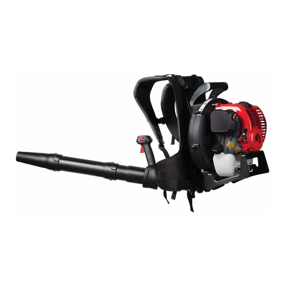
Page 5: Know Your Unit
KNOW YOUR UNIT ASSEMBLY TOOLS REQUIRED: • T-20 Torx® Screwdriver • Flat-head Screwdriver Choke Lever Air Filter Cover Starter Rope Handle Gas Cap Suspension System Shoulder Support Shoulder Stand Support Buckle Waist Support Waist Support On/Off Control Clip Throttle Grip Cruise Control Trigger Muffler... -
Page 6: Assembly Instructions
ASSEMBLY INSTRUCTIONS ASSEMBLING THE BLOWER TUBE Installing the Lower Blower Tube and Nozzle Align the bump slot on the end of the lower blower tube with the WARNING: To avoid serious personal injury and bump on the bottom end of the upper blower tube (Fig. 3, A). damage to the unit, shut the unit off before removing or installing the blower tube. - Page 7 ASSEMBLY INSTRUCTIONS The completed blower tube should look like Figure 6. WARNING: To avoid serious personal injury, make sure that the blower tubes are locked in place or firmly installed. Elbow Tube Hose Clamp Adjusting the Throttle Grip Move the throttle grip to a location on the upper blower tube that is comfortable for you (Fig.
-
Page 8: Oil And Fuel Information
OIL AND FUEL INFORMATION RECOMMENDED FUEL TYPE WARNING: OVERFILLING OIL CRANKCASE MAY Old fuel is the primary reason for improper unit performance. Use CAUSE SERIOUS PERSONAL INJURY. Check and only fresh, clean unleaded gasoline, or use TruFuel® 4-Cycle Fuel maintain the proper oil level in the crank case; it is (PN 6527238). -
Page 9: Starting/Stopping Instructions
STARTING/STOPPING INSTRUCTIONS Choke Lever WARNING: Operate this unit only in a well- ventilated outdoor area. Carbon monoxide exhaust fumes can be lethal in a confined area. WARNING: Avoid accidental starting. Make sure you are in the starting position when pulling the starter rope (Fig. - Page 10 STARTING/STOPPING INSTRUCTIONS IF USING THE OPTIONAL ELECTRIC STARTER OR POWER START BIT™ ACCESSORY STOPPING INSTRUCTIONS WARNING: Operate this unit only in a well- ventilated 1. Release your hand from the trigger. Allow the engine to cool outdoor area. Carbon monoxide exhaust fumes can be down by idling.
-
Page 11: Operating Instructions
OPERATING INSTRUCTIONS ADJUSTING THE SUSPENSION SYSTEM Place the unit’s shoulder supports over the shoulders while the unit is behind you. Close the suspension system’s waist support by sliding the waist support clips together (Fig. 17, A). Fig. 20 Fig. 17 •... -
Page 12: Maintenance And Repair Instructions
Troy-Bilt or other qualified service dealer. Fig. 22 NOTE: Maintenance, replacement, or repair of the emission control devices and system may be performed by a Troy-Bilt or other qualified service dealer. AIR FILTER MAINTENANCE NOTE: Please read the California/EPA statement that came with the... - Page 13 MAINTENANCE AND REPAIR INSTRUCTIONS Disconnect the spark plug wire. Air Filter Cover Clean dirt from around the spark Rocker plug. Remove the spark plug from the cylinder head by turning a 5/8 in. Cover socket counterclockwise. Remove the engine cover (Fig. 27). Clean dirt from around the rocker Air Filter arm cover.
-
Page 14: Cleaning And Storage
MAINTENANCE AND REPAIR INSTRUCTIONS CLEANING AND STORAGE If the clearance is not within specification: CLEANING a. Turn the adjusting nut (Fig. 30) using a 5/16 inch (8 mm) wrench WARNING: To avoid serious personal injury, always or nut driver. stop the engine and allow it to cool before cleaning or •... -
Page 15: Optional Accessory
OPTIONAL ACCESSORY ELECTRIC STARTER AND POWER START BIT™ FEATURES This unit is designed to be started with an optional electric starter or Power Start Bit™ that are sold separately. If choosing to start the unit using one of these features or have questions, please contact your local retailer or call 1-800-828-5500 in the U.S (1-800-668-1238 in Canada) for more information and purchasing. -
Page 16: Troubleshooting
TROUBLESHOOTING C A U S E A C T I O N ENGINE WILL NOT START Empty fuel tank Fill fuel tank with fuel The primer bulb was not pressed enough Press the primer bulb 10 times or until fuel is visible Old fuel (over 30 days) Drain fuel tank and add fresh fuel Fouled spark plug... -
Page 17: Specifications
SPECIFICATIONS* Engine Type ..................Air-Cooled, 4-Cycle Displacement . -
Page 18: Warranty Information
Instrucciones de mantenimiento y reparación ....30 TB4BP EC LImpieza y almacenamiento ......32 Accesorio opcional . -
Page 19: Normas Para Una Operación Segura
NORMAS PARA UNA OPERACIÓN SEGURA PARACHISPAS Los símbolos de seguridad se utilizan para llamar su atención sobre posibles peligros. Los símbolos de seguridad y sus NOTA: Para los usuarios en tierras forestales de los EE.UU. y en los explicaciones merecen toda su atención y comprensión. Los estados de California, Maine, Oregon y Washington. - Page 20 NORMAS PARA UNA OPERACIÓN SEGURA • Evite crear una fuente de ignición para el combustible • Apague siempre el motor cuando demore la operación o derramado. Limpie de la unidad inmediatamente cualquier mientras camina de un lugar hacia otro. combustible derramado antes de arrancar el motor. Mueva •...
- Page 21 NORMAS PARA UNA OPERACIÓN SEGURA • SIMBOLOS DE SEGURIDAD E INTERNACIONALES • Este manual del operador describe los símbolos y figuras de seguridad e internacionales que pueden aparecer en este producto. Lea el manual del operador para obtener información completa acerca de la seguridad, ensamble, operación y mantenimiento y reparación. SIMBOLO SIGNIFICADO SIMBOLO...
-
Page 22: Conozca Su Unidad
CONOZCA SU UNIDAD HERRAMIENTAS NECESARIAS PARA EL ENSAMBLAJE: • Destornillador Torx® T-20 • Destornillador plano Palanca del Cubierta de Manija de la obturador filtro de aire cuerda de arranque Tapa del combustible Sistema de soporte Soporte para los hombros Hebilla del soporte Soporte para los hombros Soportes de... -
Page 23: Instrucciones De Ensamble
INSTRUCCIONES DE ENSAMBLE ENSAMBLAJE DEL TUBO DE LA SOPLADORA Instalación del sopladora inferior del tubo y la boquilla Alinee la ranura de tope en el extremo del tubo inferior de la ADVERTENCIA: Para evitar lesiones personales sopladora con el tope en el extremo inferior del tubo superior graves y daños a la unidad, apague la unidad antes de de la sopladora (Fig. - Page 24 INSTRUCCIONES DE ENSAMBLE El tubo terminado de la sopladora debe parecer como en la Figura 6. ADVERTENCIA: Para evitar lesiones personales graves, asegúrese de que los tubos de la sopladora estén fijadas en su lugar o firmemente instaladas. Tubo del codo Abrazadera de la Ajuste del mango de control del regulador...
-
Page 25: Información Del Aceite Y Del Combustible
INFORMACION DEL ACEITE Y DEL COMBUSTIBLE TIPO DE COMBUSTIBLE RECOMENDADO ADVERTENCIA: EL LLENAR DEMA- SIADO EL El combustible viejo es la causa principal del mal funcionamiento de CÁRTER PUEDE CAUSAR LESIONES PERSONALES la unidad. Usa solo gasoline fresca y limpia o usa TruFuel® 4-Cycle GRAVES No podemos exagerar la importancia del Fuel (PN 6527238). -
Page 26: Instrucciones De Arranque Y Apagado
INSTRUCCIONES DE ARRANQUE Y APAGADO Palanca del obturador ADVERTENCIA: Use esta unidad sólo en un área exterior bien ventilada. Los gases de escape de monóxido de carbono pueden ser letales en un área cerrada. ADVERTENCIA: Evite los arranques accidentales. Colóquese en posición de inicio cuando tire de la cuerda de arranque (Fig. - Page 27 INSTRUCCIONES DE ARRANQUE Y APAGADO SI UTILIZA EL ARRANCADOR ELÉCTRICO O EL ACCESORIO OPCIONAL POWER BIT START™ INSTRUCCIONES DE PARADA ADVERTENCIA: Use esta unidad sólo en un área exterior bien ventilada. Los gases de escape de 1. Libere el gatillo. Deje que el motor se enfríe dejándolo funcionar monóxido de carbono pueden ser letales en un área en mínima.
-
Page 28: Instrucciones De Operación
INSTRUCCIONES DE OPERACIÓN AJUSTE DEL SISTEMA DE SOPORTE Coloque los soportes de la unidad sobre los hombros mientras la unidad esté detrás de usted. Cierre los soportes de la cintura del sistema de soporte uniendo las presillas de los soportes de la cintura (Fig. 17, A). Fig. -
Page 29: Instrucciones De Mantenimiento Y Reparación
Fig. 22 realizados por un Troy-Bilt u otro proveedor de servicio calificado. NOTA: Para ver la lista completa de términos y la cobertura de los MANTENIMIENTO DEL FILTRO DE AIRE... - Page 30 INSTRUCCIONES DE MANTENIMIENTO Y REPARACIÓN 7. Vuelva a instalar la cubierta del filtro de aire. Coloque los ganchos del lado derecha de la cubierta del filtro de aire en las ranuras del Saque los lado derecha de la placa posterior (Figs. 23 y 24). tornillos 8.
-
Page 31: Limpieza Y Almacenamiento
INSTRUCCIONES DE MANTENIMIENTO Y REPARACIÓN LIMPIEZA Y ALMACENAMIENTO LIMPIEZA Tuerca de ajuste ADVERTENCIA: Para evitar lesiones personales Balancín graves, apague siempre el motor y deje que se enfríe antes de limpiar o dar mantenimiento a la unidad. Use un cepillo pequeño para limpiar la unidad por fuera. No utilice .076–.152 mm detergentes fuertes. -
Page 32: Accesorio Opcional
ACCESORIO OPCIONAL ARRANCADOR ELÉCTRICO Y ACCESORIO DE ARRANQUE ELÉCTRICO OPCIONAL POWER START BIT™ Esta unidad está diseñada para utilizarse, de forma opcional, con un arrancador eléctrico o con un accesorio de arranque Power Start Bit™, los cuales se venden por separado. Si decide arrancar la unidad utilizando uno de estos sistemas de arranque o tiene alguna pregunta, comuníquese con su distribuidor local o llame al 1-800-828-5500, en EE.UU., (1-800-668-1238 en Canadá), para más información, así... -
Page 33: Resolución De Problemas
RESOLUCIÓN DE PROBLEMAS C A U S A A C C I Ó N EL MOTOR NO ARRANCA El tanque de combustible está vacío Llene el tanque de combustible con el combustible La pera del cebador no se oprimió lo suficiente Oprima la pera del cebador 10 veces o hasta que se vea el combustible Combustible viejo (más de 30 días) Vacíe el tanque de gasolina y añada combustible fresco... -
Page 34: Especificaciones
ESPECIFICACIONES* Tipo de motor ................Enfriado por aire, 4 ciclos Desplazamiento . - Page 35 NOTES...
- Page 36 NOTES...
- Page 37 NOTES...
- Page 38 NOTES...
Need help?
Do you have a question about the TB4BP EC and is the answer not in the manual?
Questions and answers