Troy-Bilt TB4BP EC Operator's Manual
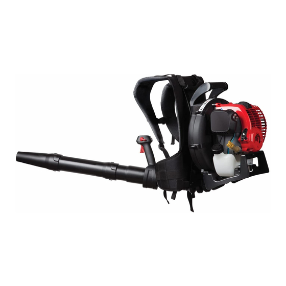
4-cycle backpack blower
Hide thumbs
Also See for TB4BP EC:
- Operator's manual (38 pages) ,
- Operator's manual (19 pages) ,
- Fast assembly manual (2 pages)
Table of Contents
Advertisement
Available languages
Available languages
Operator's Manual
4-Cycle Backpack Blower
TB4BP EC
769-06928 P02
TABLE OF CONTENTS
Service Information . . . . . . . . . . . . . . . . . . . . . . . . . . . . . . . . . . . .1
Rules for Safe Operation . . . . . . . . . . . . . . . . . . . . . . . . . . . . . . . .2
Know Your Unit . . . . . . . . . . . . . . . . . . . . . . . . . . . . . . . . . . . . . . . .5
Assembly Instructions . . . . . . . . . . . . . . . . . . . . . . . . . . . . . . . . . .6
Oil and Fuel Information . . . . . . . . . . . . . . . . . . . . . . . . . . . . . . . . .8
Starting/Stopping Instructions . . . . . . . . . . . . . . . . . . . . . . . . . . . .9
Operating Instructions . . . . . . . . . . . . . . . . . . . . . . . . . . . . . . . . .11
Maintenance and Repair Instructions . . . . . . . . . . . . . . . . . . . . . .12
Cleaning and Storage . . . . . . . . . . . . . . . . . . . . . . . . . . . . . . . . . .14
Optional Accessory . . . . . . . . . . . . . . . . . . . . . . . . . . . . . . . . . . .15
Troubleshooting . . . . . . . . . . . . . . . . . . . . . . . . . . . . . . . . . . . . . .16
Specifications . . . . . . . . . . . . . . . . . . . . . . . . . . . . . . . . . . . . . . . .17
Warranty Information . . . . . . . . . . . . . . . . . . . . . . . . . . . . . . . . . .18
SAVE THESE INSTRUCTIONS
SERVICE INFORMATION
DO NOT RETURN THIS UNIT TO THE RETAILER. PROOF OF
PURCHASE WILL BE REQUIRED FOR WARRANTY SERVICE.
For assistance regarding the assembly, controls, operation or
maintenance of the unit, please call the Customer Support Department
at 1-800-828-5500 in the United States or 1-800-668-1238 in Canada.
Additional information about the unit can be found on our website at
www.troybilt.com or www.troybilt.ca.
For service, please call the Customer Support Department to obtain a
list of authorized service dealers near you. Service on this unit, both
within and after the warranty period, should only be performed by an
authorized and approved service dealer. When servicing, use only
identical replacement parts.
All information, illustrations, and specifications in this manual are based on
the latest product information available at the time of printing. We reserve
the right to make changes at any time without notice.
Copyright© 2011 MTD SOUTHWEST INC, All Rights Reserved.
05/11
Advertisement
Chapters
Table of Contents

Related Manuals for Troy-Bilt TB4BP EC


Summary of Contents for Troy-Bilt TB4BP EC
-
Page 1: Save These Instructions
Rules for Safe Operation ....... .2 TB4BP EC Know Your Unit ........5 Assembly Instructions . -
Page 2: Rules For Safe Operation
RULES FOR SAFE OPERATION SPARK ARRESTOR NOTE The purpose of safety symbols is to attract your attention to possible dangers. The safety symbols, and their explanations, deserve your NOTE: For users on U.S. Forest Land and in the states of careful attention and understanding. - Page 3 • Use only replacement parts recommended for this tool that are • Never run the unit without the proper equipment attached. sold by a Troy-Bilt outlet. Use of any replacement parts purchased • To reduce the risk of hearing loss associated with sound level(s), elsewhere may be hazardous, and will also void your warranty.
- Page 4 RULES FOR SAFE OPERATION SAFETY AND INTERNATIONAL SYMBOLS This operator's manual describes safety and international symbols and pictographs that may appear on this product. Read the operator's manual for complete safety, assembly, operating, maintenance,` and repair information. SYMBOL MEANING SYMBOL MEANING •...
-
Page 5: Know Your Unit
KNOW YOUR UNIT TOOLS REQUIRED: • T-20 Torx® Screwdriver • Flathead Screwdriver Choke Lever Air Filter Cover Starter Rope Handle Gas Cap Suspension System Shoulder Support Shoulder Stand Support Buckle Waist Support Waist Support On/Off Control Clip Throttle Grip Cruise Control Trigger Muffler Primer Bulb... -
Page 6: Assembly Instructions
ASSEMBLY INSTRUCTIONS ASSEMBLING THE BLOWER TUBE Installing the Lower Blower Tube and Nozzle Align the bump slot on the end of the lower blower tube with the WARNING: To avoid serious personal injury and bump on the bottom end of the upper blower tube (Fig. 3, A). damage to the unit, shut the unit off before removing or installing the blower tube. - Page 7 ASSEMBLY INSTRUCTIONS The completed blower tube should look like Figure 6. WARNING: To avoid serious personal injury, make sure that the blower tubes are locked in place or firmly installed. Elbow Tube Hose Clamp Adjusting the Throttle Grip Move the throttle grip to a location on the upper blower tube that is comfortable for you (Fig.
-
Page 8: Oil And Fuel Information
OIL AND FUEL INFORMATION RECOMMENDED FUEL TYPE WARNING: OVERFILLING OIL CRANKCASE MAY Old fuel is the primary reason for improper unit performance. Be CAUSE SERIOUS PERSONAL INJURY. Check and sure to use fresh, clean, unleaded gasoline. maintain the proper oil level in the crank case; it is important and cannot be overemphasized. -
Page 9: Starting/Stopping Instructions
STARTING/STOPPING INSTRUCTIONS Choke Lever WARNING: Operate this unit only in a well- ventilated outdoor area. Carbon monoxide exhaust fumes can be lethal in a confined area. WARNING: Avoid accidental starting. Make sure you are in the starting position when pulling the starter rope (Fig. - Page 10 STARTING/STOPPING INSTRUCTIONS IF USING THE OPTIONAL ELECTRIC STARTER OR POWER START BIT™ ACCESSORY STOPPING INSTRUCTIONS WARNING: Operate this unit only in a well- ventilated 1. Release your hand from the trigger. Allow the engine to cool outdoor area. Carbon monoxide exhaust fumes can be down by idling.
-
Page 11: Operating Instructions
OPERATING INSTRUCTIONS ADJUSTING THE SUSPENSION SYSTEM Place the unit’s shoulder supports over the shoulders while the unit is behind you. Close the suspension system’s waist support by sliding the waist support clips together (Fig. 17, A). Fig. 20 Fig. 17 •... -
Page 12: Maintenance And Repair Instructions
Troy-Bilt or other qualified service dealer. NOTE: Maintenance, replacement, or repair of the emission control Fig. 22 devices and system may be performed by a Troy-Bilt or other qualified service dealer. AIR FILTER MAINTENANCE NOTE: Please read the California/EPA statement that came with the... - Page 13 MAINTENANCE AND REPAIR INSTRUCTIONS Disconnect the spark plug wire. Air Filter Cover Clean dirt from around the spark Rocker plug. Remove the spark plug from the cylinder head by turning a 5/8 in. Cover socket counterclockwise. Remove the engine cover (Fig. 27). Clean dirt from around the rocker Air Filter arm cover.
-
Page 14: Cleaning And Storage
MAINTENANCE AND REPAIR INSTRUCTIONS CLEANING AND STORAGE If the clearance is not within specification: CLEANING a. Turn the adjusting nut (Fig. 30) using a 5/16 inch (8 mm) wrench WARNING: To avoid serious personal injury, always or nut driver. turn your unit off and allow it to cool before you clean or •... -
Page 15: Optional Accessory
OPTIONAL ACCESSORY ELECTRIC STARTER AND POWER START BIT™ FEATURES This unit is designed to be started with an optional electric starter or Power Start Bit™ that are sold separately. If choosing to start the unit using one of these features or have questions, please contact your local retailer or call 1-800-828-5500 in the U.S (1-800-668-1238 in Canada) for more information and purchasing. -
Page 16: Troubleshooting
TROUBLESHOOTING C A U S E A C T I O N ENGINE WILL NOT START Empty fuel tank Fill fuel tank with fuel Primer bulb wasn't pressed enough Press primer bulb fully and slowly 10 times Old fuel (over 30 days) Drain fuel tank and add fresh fuel Fouled spark plug Replace or clean the spark plug... -
Page 17: Specifications
SPECIFICATIONS* Engine Type ..................Air-Cooled, 4-Cycle Displacement . - Page 18 MANUFACTURERʼS LIMITED WARRANTY FOR: The limited warranty set forth below is given by Troy-Bilt LLC (Troy-Bilt) No implied warranty, including any implied warranty of with respect to new merchandise purchased and used in the United merchantability or fitness for a particular purpose, applies after the States, its possessions and territories.
-
Page 19: Table Of Contents
Consignes de sécurité ....... . .20 TB4BP EC Familiarisez-vous avec votre appareil .....23 Instructions de montage . -
Page 20: Consignes De Sécurité
CONSIGNES DE SÉCURITÉ PARE-ÉTINCELLES Les symboles de sécurité attirent votre attention sur des dangers REMARQUE : à l'intention des utilisateurs opérant dans les terres potentiels. Ces symboles et leurs détails explicatifs méritent que forestières des États-Unis et dans les états de Californie, du vous les lisiez et compreniez bien. - Page 21 Elles sont disponibles auprès de votre • Pour réduire les risques de perte de l’ouïe causée par le niveau de concessionnaire Troy-Bilt. L'utilisation de pièces ou accessoires bruit, toujours porter une protection auditive lors de l’utilisation.
- Page 22 CONSIGNES DE SÉCURITÉ • SYMBOLES DE SÉCURITÉ ET INTERNATIONAUX • Ce manuel de l'utilisateur décrit les symboles et pictogrammes de sécurité et internationaux pouvant apparaître sur ce produit. Consultez le manuel de l'utilisateur pour les informations concernant la sécurité, le montage, le fonctionnement, l'entretien et les réparations. SYMBOLE SIGNIFICATION SYMBOLE...
-
Page 23: Familiarisez-Vous Avec Votre Appareil
FAMILIARISEZ-VOUS AVEC VOTRE APPAREIL OUTILS REQUIS : • Tournevis T-20 Torx® • Tournevis à tête plate Levier Couvercle du logement d’étranglement de filtre à air Poignée du cordon du démarreur Couvercle du réservoir d’essence Systeme de support Support d’epaule Boucle de la Pied support d’epaule Support de... -
Page 24: Instructions De Montage
INSTRUCTIONS DE MONTAGE ASSEMBLAGE DU TUBE DU SOUFFLEUR Installer les tube de soufflage inférieurs et la buse Aligner l’encoche sur l’extrémité du tube de soufflage inférieur AVERTISSEMENT : Afin d’éviter de graves avec la bosse sur l’extrémité inférieure du tube de soufflage blessures et éviter d’endommager l’appareil, coupez le supérieur (Fig. - Page 25 INSTRUCTIONS DE MONTAGE Le souffleur assemblé devrait ressembler à la figure 6. AVERTISSEMENT : Afin d’éviter de graves blessures assurez-vous que les tubes du souffleur sont bien verrouillées et serrées en place. Tube en coude Collier de serrage Ajuster la prise de la manette des gaz Bougez la prise de la manette des gaz vers un endroit sur le tube de soufflage supérieur qui vous est confortable (Fig.
-
Page 26: Informations Sur L'huile Et Le Carburant
INFORMATIONS SUR L’HUILE ET LE CARBURANT TYPE CARBURANT RECOMMANDÉ AVERTISSEMENT : LE REMPLISSAGE EXCESSIF En général, si l'appareil ne fonctionne pas correctement, c'est que l’essence DU CARTER-MOTEUR PEUT ANTRAÎNER DES est vieux. Prenez soin d'utiliser d’essence sans plomb frais et propre. BLESSURES GRAVES. -
Page 27: Instructions De Démarrage Et Arrêt
INSTRUCTIONS DE DÉMARRAGE ET ARRÊT Levier d’étrangleur AVERTISSEMENT : n’utiliser l’outil qu’à l’extérieur, dans un endroit bien aéré. Les émanations d’oxyde de carbone dans un endroit confiné peuvent être mortelles. AVERTISSEMENT : éviter le démarrage accidentel. Se tenir en position de démarrage pour lancer le moteur (Fig. - Page 28 INSTRUCTIONS DE DÉMARRAGE ET ARRÊT SI VOUS UTILISEZ LE DÉMARREUR ÉLECTRIQUE ELECTRIC STARTER OU POWER START BIT™ DISPONIBLE EN OPTION CONSIGNES POUR ARRETER L’APPAREIL AVERTISSEMENT : n’utiliser l’outil qu’à l’extérieur, Relâcher la gâchette et laisser le moteur refroidir en le faisant dans un endroit bien aéré.
-
Page 29: Mode D'emploi
MODE D’EMPLOI AJUSTER LE SYSTEME DE SUPPORT Placer les supports d’épaules de l’appareil sur les épaules et l'appareil sur le dos. Fermer le support de taille du système de support en cliquant les deux attaches (Fig. 17, A). Fig. 20 Fig. -
Page 30: Entretien Et Réparations
Si vous n’êtes pas certain d’être capable d’effectuer ces procédures, emmenez l’appareil dans un magasin Troy-Bilt ou chez un concessionnaire agréé. REMARQUE : L’entretien, le remplacement, ou la réparation des dispositifs et systèmes de commande peuvent être effectués dans un magasin Troy-Bilt ou chez un concessionnaire agréé. - Page 31 ENTRETIEN ET RÉPARATIONS 8. Pivotez le couvercle vers la droite jusqu’à ce que la languette du couvercle du filtre s’enfonce d’un déclic dans la fente sur le Retirez côté droite du boîtier du filtre (Fig. 25). les vis Couvre du filtre à...
-
Page 32: Nottoyage Et Entreposage
ENTRETIEN ET RÉPARATIONS NOTTOYAGE ET ENTREPOSAGE NETTOYAGE DE L’APPAREIL Écrou de réglage AVERTISSEMENT : pour éviter des blessures graves, éteignez toujours le coupe-bordures et laissez- Culbuteur la refroidir avant tout nettoyage ou entretien. Nettoyez les évents ou l’extérieur de l’appareil avec une petite brosse. N'employez pas de détergents concentrés ou de nettoyants à... -
Page 33: Accessoire En Option
ACCESSOIRE EN OPTION FONCTIONNALITÉS DÉMARREUR ÉLECTRIQUE ET POWER START BIT™ Cet appareil est conçu pour être démarré avec un démarreur électrique ou Power Start Bit™ qui sont vendus séparément. Si vous choisissez de démarrer l'appareil à l’aide de l'une de ces fonctionnalités ou si vous avez des questions, contactez votre distributeur local ou appelez le 1-800-828-5500 si vous résidez aux États-Unis, (1-800-668-1238 au Canada) pour plus d’informations ou... -
Page 34: Tableau De Dépannage
DÉPANNAGE C A U S E S O L U T I O N LE MOTEUR REFUSE DE DÉMARRER Réservoir de carburant vide Remplissez-le de carburant frais La poire d'amorçage n'a pas été pressée assez fort Pressez-la complètement et lentement de 10 fois Carburant trop ancien (de plus de 30 jours) Vidangez le réservoir de carburant et remplissez-le de carburant frais Bougie encrassée... -
Page 35: Caractéristiques
CARACTÉRISTIQUES* Type de moteur ................Refroidi par air, 4-temps Cylindrée . -
Page 36: Garantie
écrite ci-dessus concernant les pièces qui sont identifiées. Aucune autre garantie ou Troy-Bilt LLC garantit ce produit contre tout vice de matière ou de caution expresse, écrite ou orale, à l'exception de celle mentionnée façon pendant une période de deux (2) ans à... -
Page 37: Llamadas A Apoyo Al Cliente
Normas para una operación segura ..... . .38 TB4BP EC Conozca su unidad ........41 Instrucciones de ensamble . -
Page 38: Normas Para Una Operación Segura
NORMAS PARA UNA OPERACIÓN SEGURA PARACHISPAS Los símbolos de seguridad se utilizan para llamar su atención sobre posibles peligros. Los símbolos de seguridad y sus NOTA: Para los usuarios en tierras forestales de los EE.UU. y en los explicaciones merecen toda su atención y comprensión. Los estados de California, Maine, Oregon y Washington. - Page 39 NORMAS PARA UNA OPERACIÓN SEGURA • Evite crear una fuente de ignición para el combustible • Apague siempre el motor cuando demore la operación o derramado. Limpie de la unidad inmediatamente cualquier mientras camina de un lugar hacia otro. combustible derramado antes de arrancar el motor. Mueva •...
- Page 40 NORMAS PARA UNA OPERACIÓN SEGURA • SIMBOLOS DE SEGURIDAD E INTERNACIONALES • Este manual del operador describe los símbolos y figuras de seguridad e internacionales que pueden aparecer en este producto. Lea el manual del operador para obtener información completa acerca de la seguridad, ensamble, operación y mantenimiento y reparación. SIMBOLO SIGNIFICADO SIMBOLO...
-
Page 41: Conozca Su Unidad
CONOZCA SU UNIDAD SE NECESITAN HERRAMIENTAS: • Destornillador Torx® T-20 • Destornillador plano Palanca del Cubierta de Manija de la obturador filtro de aire cuerda de arranque Tapa del combustible Sistema de soporte Soporte para los hombros Hebilla del soporte Soporte para los hombros Soportes de... -
Page 42: Instrucciones De Ensamble
INSTRUCCIONES DE ENSAMBLE ENSAMBLAJE DEL TUBO DE LA SOPLADORA Instalación del sopladora inferior del tubo y la boquilla Alinee la ranura de tope en el extremo del tubo inferior de la ADVERTENCIA: Para evitar lesiones personales sopladora con el tope en el extremo inferior del tubo superior graves y daños a la unidad, apague la unidad antes de de la sopladora (Fig. - Page 43 INSTRUCCIONES DE ENSAMBLE El tubo terminado de la sopladora debe parecer como en la Figura 6. ADVERTENCIA: Para evitar lesiones personales graves, asegúrese de que los tubos de la sopladora estén fijadas en su lugar o firmemente instaladas. Tubo del codo Abrazadera de la Ajuste del mango de control del regulador...
-
Page 44: Información Del Aceite Y Del Combustible
INFORMACION DEL ACEITE Y DEL COMBUSTIBLE TIPO DE COMBUSTIBLE RECOMENDADO ADVERTENCIA: EL LLENAR DEMA- SIADO EL El combustible viejo es la causa principal del mal funcionamiento de CÁRTER PUEDE CAUSAR LESIONES PERSONALES la unidad. Asegúrese de usar combustible nuevo, limpio y sin plomo. GRAVES No podemos exagerar la importancia del control y mantenimiento del nivel correcto de aceite en NOTA: Este es un motor de cuatro ciclos. -
Page 45: Instrucciones De Arranque Y Apagado
INSTRUCCIONES DE ARRANQUE Y APAGADO Palanca del obturador ADVERTENCIA: Use esta unidad sólo en un área exterior bien ventilada. Los gases de escape de monóxido de carbono pueden ser letales en un área cerrada. ADVERTENCIA: Evite los arranques accidentales. Colóquese en posición de inicio cuando tire de la cuerda de arranque (Fig. - Page 46 INSTRUCCIONES DE ARRANQUE Y APAGADO SI UTILIZA EL ARRANCADOR ELÉCTRICO O EL ACCESORIO OPCIONAL POWER BIT START™ INSTRUCCIONES DE PARADA ADVERTENCIA: Use esta unidad sólo en un área exterior bien ventilada. Los gases de escape de 1. Libere el gatillo. Deje que el motor se enfríe dejándolo funcionar monóxido de carbono pueden ser letales en un área en mínima.
-
Page 47: Instrucciones De Operación
INSTRUCCIONES DE OPERACIÓN AJUSTE DEL SISTEMA DE SOPORTE Coloque los soportes de la unidad sobre los hombros mientras la unidad esté detrás de usted. Cierre los soportes de la cintura del sistema de soporte uniendo las presillas de los soportes de la cintura (Fig. 17, A). Fig. -
Page 48: Instrucciones De Mantenimiento Y Reparación
Fig. 22 realizados por un Troy-Bilt u otro proveedor de servicio calificado. NOTA: Para ver la lista completa de términos y la cobertura de los MANTENIMIENTO DEL FILTRO DE AIRE... - Page 49 INSTRUCCIONES DE MANTENIMIENTO Y REPARACIÓN 7. Vuelva a instalar la cubierta del filtro de aire. Coloque los ganchos del lado derecha de la cubierta del filtro de aire en las ranuras del Saque los lado derecha de la placa posterior (Figs. 23 y 24). tornillos 8.
-
Page 50: Limpieza Y Almacenamiento
INSTRUCCIONES DE MANTENIMIENTO Y REPARACIÓN LIMPIEZA Y ALMACENAMIENTO LIMPIEZA Tuerca de ajuste ADVERTENCIA: Para evitar graves lesiones Balancín personales, apague siempre su unidad y espere que se enfríe antes de limpiarlo o realizar cualquier tipo de mantenimiento. Use un cepillo pequeño para limpiar la parte exterior de la unidad. .076–.152 mm No use detergentes fuertes. -
Page 51: Accesorio Opcional
ACCESORIO OPCIONAL ARRANCADOR ELÉCTRICO Y ACCESORIO DE ARRANQUE ELÉCTRICO OPCIONAL POWER START BIT™ Esta unidad está diseñada para utilizarse, de forma opcional, con un arrancador eléctrico o con un accesorio de arranque Power Start Bit™, los cuales se venden por separado. Si decide arrancar la unidad utilizando uno de estos sistemas de arranque o tiene alguna pregunta, comuníquese con su distribuidor local o llame al 1-800-828-5500, en EE.UU., (1-800-668-1238 en Canadá), para más información, así... -
Page 52: Resolución De Problemas
RESOLUCIÓN DE PROBLEMAS C A U S A A C C I Ó N EL MOTOR NO ARRANCA El tanque de combustible está vacío Llene el tanque de combustible con el combustible La bombilla de cebado no fue oprimida lo suficiente Oprima la bombilla de cebado total y lentamente de 10 veces Combustible viejo (más de 30 días) Vacíe el tanque de gasolina y añada combustible fresco... -
Page 53: Especificaciones
ESPECIFICACIONES* Tipo de motor ................Enfriado por aire, 4 ciclos Desplazamiento . - Page 54 NOTES...
- Page 55 NOTES...
-
Page 56: Garantía
Troy-Bilt LLC garantiza este producto contra defectos en el material y la identificadas. Exceptuando lo mencionado anteriormente, mano de obra durante un período de dos (2) años, a partir de la fecha ninguna otra garantía expresa bien sea escrita o verbal con...
Need help?
Do you have a question about the TB4BP EC and is the answer not in the manual?
Questions and answers