Table of Contents
Advertisement
Quick Links
Advertisement
Table of Contents

Related Manuals for F5 BIG-IP 11050


Summary of Contents for F5 BIG-IP 11050
- Page 1 Platform Guide: 11050 MAN-0322-03...
-
Page 3: Table Of Contents
Table of Contents Table of Contents Legal Notices.....................5 Chapter 1: The 11050 Platform....................7 About the 11050 Platform....................8 Components provided with the platform................9 Peripheral hardware requirements..................9 LCD panel........................10 About LCD menus....................10 Using LCD menus....................12 Indicator LEDs.........................13 Indicator LED behavior..................13 Status LED......................13 Power supply LEDs....................14 LED alert conditions....................14 Defining custom alerts...................14... - Page 4 Table of Contents Installing to a 19-inch rack using a center-mounting kit........34 Installing to a 23-inch rack using a center-mounting kit........35 About the quick-install rail kit....................36 Connecting the cables and other hardware..............37 Configuring a management IP address................38 Chapter 3: Platform Maintenance...................39 About platform maintenance....................40 About AC power supplies..................40 About DC power supplies..................42...
-
Page 5: Legal Notices
2013, F5 Networks, Inc. All rights reserved. F5 Networks, Inc. (F5) believes the information it furnishes to be accurate and reliable. However, F5 assumes no responsibility for the use of this information, nor any infringement of patents or other rights of third parties which may result from its use. - Page 6 Legal Notices interference when the equipment is operated in a commercial environment. This unit generates, uses, and can radiate radio frequency energy and, if not installed and used in accordance with the instruction manual, may cause harmful interference to radio communications. Operation of this equipment in a residential area is likely to cause harmful interference, in which case the user, at his own expense, will be required to take whatever measures may be required to correct the interference.
-
Page 7: Chapter 1: The 11050 Platform
Chapter The 11050 Platform • About the 11050 Platform • Components provided with the platform • Peripheral hardware requirements • LCD panel • Indicator LEDs • Platform interfaces • Always-On Management... -
Page 8: About The 11050 Platform
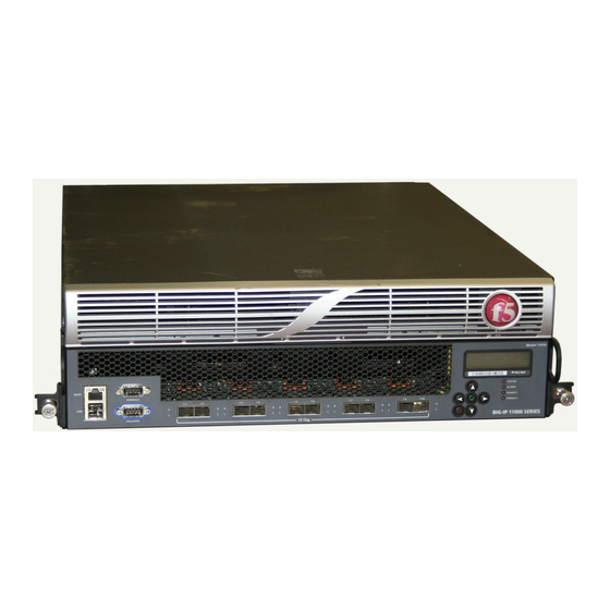
The 11050 Platform About the 11050 Platform ® The BIG-IP 11050 platform is a powerful system that is capable of managing traffic for any size of enterprise. The 11050 platform is available in a Network Equipment-Building System (NEBS) compliant version. Before you install the 11050 platform, review helpful information about the controls and ports located on both the front and the back of the platform. -
Page 9: Components Provided With The Platform
Platform Guide: 11050 Components provided with the platform When you unpack the platform, verify that the following components are included. Quantity Hardware Power cables (black), AC power only DC terminal blocks, DC power option only Serial failover cable (blue) Console cable (beige) Front-mounting kit (11000 Series non-NEBS platform only) Four-point rack mounting kit (11050 NEBS platform only) Center-mounting kits, 19- and 23-inch (11050 NEBS platform... -
Page 10: Lcd Panel
The 11050 Platform LCD panel The LCD panel provides the ability to manage the unit without attaching a console or network cable. Figure 3: The LCD panel and control buttons About LCD menus There are three menus on the LCD panel. You can configure the display options to meet your needs. LCD config menu You can use the LCD config menu to adjust the display properties of the LCD panel. - Page 11 Platform Guide: 11050 Screens menu You can use the Screens menu to specify the information that is displayed on the default screens. Option Description DateScreen Displays the date and time. InfoScreen Displays the information screen menu. MACscreen Displays the MAC addresses on the unit. SysinfoScreen Displays system information.
-
Page 12: Using Lcd Menus
Hold the X button for four seconds to put the unit in standby mode and power off the host subsystem. F5 Networks recommends that you halt the system before you power off the system in this manner. Rebooting the unit Hold the Check button for four seconds to reset the unit. -
Page 13: Indicator Leds
Platform Guide: 11050 Clearing alerts Press the Check button to clear any alerts on the LCD screen. You must clear any alerts on the screen before you can use the LCD panel. Indicator LEDs The behavior of each LED indicates the status of the system. Indicator LED behavior The indicator LEDs behave in a specific manner to indicate system or component status. -
Page 14: Power Supply Leds
The 11050 Platform Power supply LEDs The power supply LEDs indicate the operating state of the power supplies. Power 1 state Power 2 state Description green solid green solid Power supply is present and operating properly. yellow solid yellow solid Power supply is present, but not operating properly. -
Page 15: Additional Indicator Led Status Conditions
Platform Guide: 11050 down." { snmptrap OID=".1.3.6.1.4.1.3375.2.4.0.12"; lcdwarn description="Node address down" priority="1" alert BIGIP_MCPD_MCPDERR_POOL_MEMBER_MON_UP "Pool member (.*?):(.*?) monitor status up." snmptrap OID=".1.3.6.1.4.1.3375.2.4.0.11" alert BIGIP_MCPD_MCPDERR_NODE_ADDRESS_MON_UP "Node (.*?) monitor status up." snmptrap OID=".1.3.6.1.4.1.3375.2.4.0.13" 5. Save the file and exit the text editor. The front panel LEDs now indicate when a node is down. - Page 16 The 11050 Platform Viewing the status of a specific interface using tmsh You can use to view the status of a specific interface on a platform. tmsh 1. Open the Traffic Management Shell (tmsh). tmsh 2. Change to the network module. The system prompt updates with the module name: user@bigip01(Active)(/Common)(tmos.net)# 3.
-
Page 17: About Interface Media Type And Duplex Mode
Platform Guide: 11050 Viewing the status of all interfaces using the Configuration utility You can use the Configuration utility to view the status of all interfaces on the platform. 1. On the Main tab, expand Network, and click Interfaces. This displays the list of available interfaces. 2. -
Page 18: Network Interface Led Behavior
The 11050 Platform 10GBaseER full 1000BaseCX full 10GBaseLR full 1000BaseT half 10GBaseSR full 1000BaseT full 10GBaseT full 1000BaseSX full 10SFP+Cu full auto 40GBaseSR4 full none 40GBaseLR4 full no-phy 100BaseTX half Viewing valid media types for an interface using tmsh You can use to view the valid media types for an interface. -
Page 19: Optical Transceiver Specifications
Important: 1000Base-T network segments have a maximum length of 328 feet (100 meters) and must use Category 5 cable minimum. F5 recommends Category 5e or Category 6. Note: F5 Gigabit Ethernet 1000Base-T Copper SFP modules comply with IEEE standards 802.3ab (1000BASE-T). - Page 20 Important: You must ensure suitability of both the optical fiber and the laser transceiver on the other end. Important: Fiber cables must be a minimum of two meters, according to IEEE Std 802.3ae. Note: F5 Gigabit Ethernet modules comply with IEEE standards 802.3ab (1000BASE-T) and 802.3z (1000BASE-SX, 1000BASE-LX).
- Page 21 Important: You must ensure suitability of both the optical fiber and the laser transceiver on the other end. Important: Fiber cables must be a minimum of two meters, according to IEEE Std 802.3ae. Note: F5 10 Gigabit Ethernet modules comply with IEEE standards 802.3ae 10GBASE-LR/LW, 10GBASE-SR 10G Ethernet.
- Page 22 Important: You must ensure suitability of both the optical fiber and the laser transceiver on the other end. Important: Fiber cables must be a minimum of two meters, according to IEEE Std 802.3ae. Note: F5 10GE optical modules comply with IEEE Std 802.3ae. Module...
-
Page 23: Cable Pinout Specifications
Platform Guide: 11050 Module Laser emitter Connector type Operating Supported distance/cable platforms specifications 10GBASE-LR 1310 nm 10 kilometers 8400, 8800, (Long Range) (single-mode) maximum for VIPRION 4400 Ethernet ITU-T G.652 SMF Series, B4100 Transceiver Important: Specifications are subject to change without notification. Cable pinout specifications The following pinouts describe how specified connectors are wired. -
Page 24: Always-On Management
The 11050 Platform Always-On Management ® The Always-On Management (AOM) subsystem enables you to manage the BIG-IP system remotely using SSH or serial console, even if the host is powered down. The AOM Command Menu operates independently ® of the BIG-IP Traffic Management Operating System (TMOS). -
Page 25: Accessing The Aom Command Menu From The Serial Console
Platform Guide: 11050 Number/Letter Option Description AOM platform information Displays information about the platform, including serial number and MAC address. Accessing the AOM Command Menu from the serial console You can access the AOM Command Menu through the host console shell (hostconsh) using the front panel serial console. -
Page 27: Chapter 2: Platform Installation
Chapter Platform Installation • About platform installation • Determining which rack mounting kit to use • About general recommendations for rack mounting • About the front-mounting kit • About the four-point rack mounting kit • About the center-mounting kits • About the quick-install rail kit •... -
Page 28: About Platform Installation
Leaving at least 100 mm spacing from the front panel of the unit to the rack front or rack door provides enough room for you to route the cables without excessive bending or insulation damage. Caution: To prevent personal injury or damage to the unit, F5 Networks strongly recommends that at least two people perform the installation. -
Page 29: About The Front-Mounting Kit
Platform Guide: 11050 About the front-mounting kit You can use the front-mounting kit if you are installing into a two-post rack. Note: You should use the front-mounting kit to install 11000 series platforms only if you are installing the platform into a two-post rack. For installing the platform into all other types of racks or cabinets, you should use the quick-install rail kit. -
Page 30: About The Four-Point Rack Mounting Kit
Platform Installation 3. Repeat steps 1 and 2 for the other bracket. 4. Lift the unit into place in the rack. Caution: Due to the weight of the chassis, this step requires two people. 5. Secure the front-mounting brackets to the rack using four rack manufacturer-provided screws. The unit must be securely fastened to the rack to provide adequate stability and to prevent the unit from falling out of the rack. -
Page 31: Installing Using A Four-Point Rack Mounting Kit
Platform Guide: 11050 Installing using a four-point rack mounting kit Before you install this platform, review the environmental guidelines to make sure that you are installing and using the platform in the appropriate environment. Caution: Due to the weight of this platform, two people are required to unpack and install it. Failing to use two people can result in severe personal injury or equipment damage and might violate safety regulations. - Page 32 Platform Installation 4. Secure the rear bracket to the unit using six of the SEMS screws provided with the kit. Use 18 to 20 inch-pounds (2.0 to 2.3 Newton-meters) of torque on these screws. 5. Repeat steps 1 through 4 for to attach the front- and rear-mounting brackets to the other side of the unit. 6.
-
Page 33: About The Center-Mounting Kits
Platform Guide: 11050 7. Lift the unit into place in the rack. Caution: Due to the weight of the chassis, this step requires two people. 8. Use the guide pins on the rear brackets to guide the brackets into the rear-mount support. 9. -
Page 34: Center-Mounting Kit Hardware
Platform Installation If you are installing the 11050 NEBS platform into a 23-inch telco-style rack, you use the larger set of center-mounting brackets. Figure 5: Center-mounting brackets for 23-inch rack Center-mounting kit hardware The center-mounting kit includes these parts. Quantity Hardware center-mounting brackets for 19-inch rack center-mounting brackets for 23-inch rack... -
Page 35: Installing To A 23-Inch Rack Using A Center-Mounting Kit
Platform Guide: 11050 3. Repeat steps 1 and 2 for the other bracket. 4. Lift the unit into place in the rack. Caution: Due to the weight of the chassis, this step requires two people. 5. Secure the unit to the rack using four rack manufacturer-provided screws on each side. The unit must be securely fastened to the rack to provide adequate stability and to prevent the unit from falling out of the rack. -
Page 36: About The Quick-Install Rail Kit
Platform Installation Caution: The center-mounting kits are only intended for installing the 11050 NEBS platform into a 19-inch or 23-inch telco-style (two-post rack). For installing the NEBS platform into all other types of racks or cabinets, you should use the four-point rack mounting kit. This platform includes center-mounting brackets that you can use to attach the unit directly to a 23-inch telco-style rack. -
Page 37: Connecting The Cables And Other Hardware
Important: In the event that network access is impaired or not yet configured, the serial console might be the only way to access the unit. F5 Networks recommends that you perform all installations and upgrades using the serial console, as these procedures require reboots, in which network connectivity is lost temporarily. -
Page 38: Configuring A Management Ip Address
Optionally, you should run the latest version of the qkview utility. This utility collects configuration and diagnostic information about your system into a single file that you can provide to F5 Technical Support to aid in troubleshooting. For more information, see http://support.f5.com/kb/en-us/solutions/public/1000/800/sol1858.html... -
Page 39: Chapter 3: Platform Maintenance
Chapter Platform Maintenance • About platform maintenance... -
Page 40: About Platform Maintenance
Caution: As a safety precaution, the socket outlet must be installed near the equipment and be easily accessible. Important: This product is sensitive to electrostatic discharge (ESD). F5 Networks recommends that you use proper ESD grounding procedures and equipment when you install or maintain the unit. - Page 41 Platform Guide: 11050 Important: F5 Networks strongly recommends that you use only one power supply type (AC or DC) in a platform. Note: Depending on the model and revision of the power supply, you might need either a Phillips or a slotted screwdriver to replace the power supply.
-
Page 42: About Dc Power Supplies
Platform Maintenance 5. Ensure that the latch on the new power supply is in the down position and slide the power supply into the power supply slot until the latch engages. 6. Rotate the latch upward to fully seat the power supply. 7. - Page 43 DC-powered platforms will be installed. Important: This product is sensitive to electrostatic discharge (ESD). F5 Networks recommends that you use proper ESD grounding procedures and equipment when you install or maintain the unit.
- Page 44 You can control the power from the rack switch or the DC power source. Important: When you connect the DC power source, F5 Networks recommends that you follow the safety requirements defined for the facilities where the DC-powered platforms will be installed.
-
Page 45: About The Fan Tray
The fans in the fan tray run constantly while the unit is on. Over time, the fans can wear out, requiring you to replace the fan tray. Important: This product is sensitive to electrostatic discharge (ESD). F5 Networks recommends that you use proper ESD grounding procedures and equipment when you install or maintain the unit. -
Page 46: About 11000 Series Platform Drive Options
You do not need special tools to replace the fan tray. You do not need to power down the unit when replacing the fan tray; however, F5 Networks highly recommends that you do not leave the unit operating without a fan tray for longer than 30 seconds. - Page 47 When replacing SSDs, you must replace both of the dual-disk drive sleds installed in the platform. Installing a hard disk drive or solid-state drive After you receive a hard disk drive sled or solid-state drive sled from F5 Networks, you can install it into your platform.
- Page 48 The BIG-IP 11050 platforms support hard disk drive mirroring using RAID. You can add the replacement hard disk drive sled that you received from F5 Networks to the system. Identifying a faulty hard disk drive Before you remove the hard disk drive from the system, you should first identify the faulty hard disk drive.
- Page 49 Next, you can physically remove the hard disk drive and replace it with the new one that you received from F5 Networks. You do not have to power down the system before you remove the hard disk drive. Replacing a hard disk drive After you have identified and removed the faulty hard disk drive from the platform, you can install the replacement drive that you received from F5 Networks.
- Page 50 Platform Maintenance Note: If after a few seconds, you do not see the recently-added hard disk drive in the disk summary, the drive might not be seated properly. If this occurs, remove and reinsert the hard disk drive. 7. Add the replacement drive (HD2 in the example) to the array by typing the following command: tmsh modify sys raid array MD1 add HD2 The status of the replacement drive should change to replicating, and the STAT LED should change to solid green.
-
Page 51: Appendix A: Environmental Guidelines
Appendix Environmental Guidelines • General environmental and installation guidelines • Guidelines for AC-powered equipment • Guidelines for DC-powered equipment • NEBS platform guidelines • Platform airflow diagram... -
Page 52: General Environmental And Installation Guidelines
Do not plug the unit into a branch circuit shared by more electronic equipment than the circuit is designed to manage safely at one time. Important: This product is sensitive to electrostatic discharge (ESD). F5 Networks recommends that you use proper ESD grounding procedures and equipment when you install or maintain the unit. -
Page 53: Guidelines For Ac-Powered Equipment
Platform Guide: 11050 Guidelines for AC-powered equipment An AC-powered installation must meet the following requirements: • Use a 20 amp external branch circuit protection device to install the unit. • Use one power feed for each individual power supply. Important: The platform must be installed in a RESTRICTED ACCESS LOCATION, such as a central office or customer premises environment. -
Page 54: Nebs Platform Guidelines
Environmental Guidelines NEBS platform guidelines The following information applies to the Network Equipment-Building System (NEBS) version of the 11050 platform. This equipment meets NEBS requirements per GR-63-CORE. This equipment is suitable for installation in the following: • Network Telecommunication Facilities •... - Page 55 Platform Guide: 11050 Figure 13: Airflow in the 11050 platform...
-
Page 57: Appendix B: Platform Specifications
Appendix Platform Specifications • General specifications for system features • Platform hardware specifications • Platform operating specifications • Safety requirements • EMC requirements • Acoustic, airflow, and altitude specifications... -
Page 58: General Specifications For System Features
Platform Specifications General specifications for system features ® This table lists general specifications for BIG-IP system features for the 11050 platform. Item Specification Server/Node operating system compatibility Load balancing of any TCP/IP operating system: 32- ® ® and 64-bit Windows operating systems;... -
Page 59: Platform Operating Specifications
Minimum start up voltage: 44 VDC Note: Power supply will not start below 44 VDC. Important: Specifications are subject to change without notification. Important: F5 Networks only provides support for F5-branded optical modules. Platform operating specifications This table lists operating specifications for the 11050 platform. -
Page 60: Safety Requirements
Platform Specifications Item Specification Maximum power draw (DC power) 48VDC input: 488 W Typical heat generated (AC power) 110VAC input: 1501 BTU/hour 220VAC input: 1590 BTU/hour Typical heat generated (DC power) 48VDC input: 1450 BTU/hour Maximum heat generated (AC power) 1829 BTU/hour Maximum heat generated (DC power) 1665 BTU/hour... - Page 61 Platform Guide: 11050 European Union This equipment complies with the following requirements of the EMC Directive 2004/108/EC: As Telecommunication Network Equipment (TNE) in Both Telecom Centers and Other than Telecom Centers per (as applicable): Directive Required Limits ESTI EN 300 386 V1.3.3 (2005-04) 55022:2006 + C1:2006 Class A 61000-3-2:2006...
-
Page 62: Acoustic, Airflow, And Altitude Specifications
Platform Specifications Acoustic, airflow, and altitude specifications This table lists acoustic levels, airflow movement, and operational altitude specifications for the 11050 platform. Specification type Detail Units Value Acoustic Front Left Right Rear Altitude Operational Feet 6,000 Non-operational Feet 40,000 Airflow Open air 285 (maximum) Important: Specifications are subject to change without notification. -
Page 63: Appendix C: China Rohs Requirements
Appendix China RoHS Requirements • Hazardous substance levels for China... -
Page 64: Hazardous Substance Levels For China
China RoHS Requirements Hazardous substance levels for China ® This table shows how the F5 Networks 11050 platform components conform to the Restriction of Hazardous Substances Directive (RoHS) standards for China. -
Page 65: Appendix D: Repackaging Guidelines
Appendix Repackaging Guidelines • About repackaging the platform... -
Page 66: About Repackaging The Platform
Repackaging Guidelines About repackaging the platform ® If it becomes necessary to transport the platform to another location or return it to F5 Networks, the following guidelines will help ensure that you repackage the platform properly. Important: Before returning any equipment, contact F5 Networks to obtain a Return Material Authorization (RMA) case number. - Page 67 Platform Guide: 11050 5. Place the accessory box on the foam insert. 6. Close and seal the shipping box.
- Page 69 Index Index acoustic specifications data communications equipment (DCE) AC-powered equipment data terminal equipment (DTE) guidelines Date and Time screen AC power supply DC-powered equipment about guidelines hot swapping NEBS guidelines administrative environment support DC power supply airflow specifications connecting the DC power source Alarm LED hot swapping behavior...
- Page 70 Index guidelines (continued) environmental NEBS LCD config menu LCD menus repackaging using LCD panel halting backlight option halt operation brightness option hard disk drive contrast option control buttons identifying a faulty hard disk drive menus installing pausing on a screen hard disk drive replacement hardware for AC-powered equipment...
- Page 71 Index redundancy system pinouts redundant system configuration 15, for cables See also device service clustering. for console port remote administration for failover port repackaging specifications about platform platform about replaceable components airflow components provided AC power supply cooling system DC power supply 42, FIPS drive options installing...
- Page 72 Index system resetting resolving when locked up USB port supported CD/DVD-ROM drives System information screen System menu ventilation telco-style rack TMOS, See Traffic Management Operating System. tmsh, See Traffic Management Shell. Traffic Management Operating System warnings environmental relation to AOM Web server application compatibility Traffic Management Shell transporting the platform...
Need help?
Do you have a question about the BIG-IP 11050 and is the answer not in the manual?
Questions and answers