Table of Contents
Advertisement
Quick Links
Advertisement
Table of Contents

Related Manuals for F5 BIG-IP 8900


Summary of Contents for F5 BIG-IP 8900
- Page 1 Platform Guide: 8900 MAN-0330-03...
-
Page 3: Table Of Contents
Table of Contents Table of Contents Legal Notices..........................7 The 8900 Platform........................9 About the 8900 Platform....................9 Components provided with the platform................10 Peripheral hardware requirements...................10 LCD panel........................10 About LCD menus....................11 Using LCD menus....................12 Indicator LEDs.........................13 Indicator LED behavior..................13 Status LED......................14 Power supply LEDs....................14 LED alert conditions....................14 Defining custom alerts...................15 Additional indicator LED status conditions............15... - Page 4 Acoustic, airflow, and altitude specifications..............53 China RoHS Requirements......................55 Hazardous substance levels for China................55 Returned Material Data Security Statement................57 About returned material data security................57 About memory technologies used in F5 equipment............57 Volatile memory.....................57 Battery-backed volatile memory................57 Non-volatile memory.....................57 About removing data from F5 components..............58...
- Page 5 Table of Contents Removing sensitive data from storage drives............58 Removing IP address data from Always-On Management........59 Removing sensitive data from an internal hardware security module (HSM)..59...
- Page 6 Table of Contents...
-
Page 7: Legal Notices
2013, F5 Networks, Inc. All rights reserved. F5 Networks, Inc. (F5) believes the information it furnishes to be accurate and reliable. However, F5 assumes no responsibility for the use of this information, nor any infringement of patents or other rights of third parties which may result from its use. - Page 8 Legal Notices interference when the equipment is operated in a commercial environment. This unit generates, uses, and can radiate radio frequency energy and, if not installed and used in accordance with the instruction manual, may cause harmful interference to radio communications. Operation of this equipment in a residential area is likely to cause harmful interference, in which case the user, at his own expense, will be required to take whatever measures may be required to correct the interference.
-
Page 9: The 8900 Platform
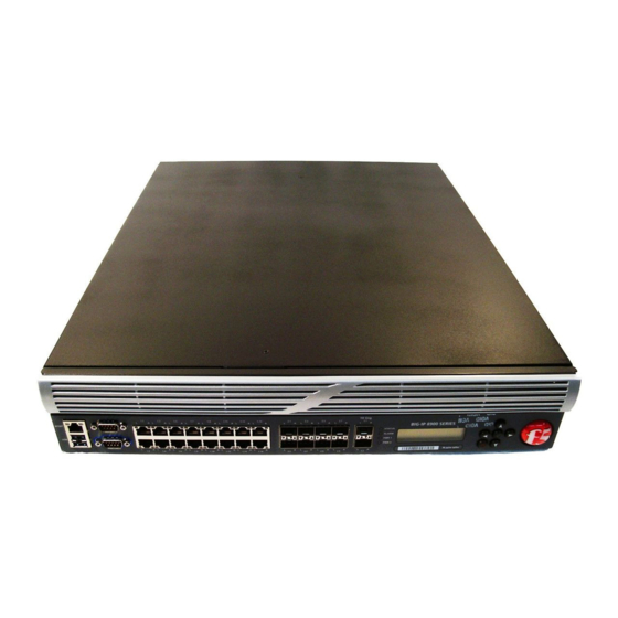
The 8900 Platform About the 8900 Platform ® The BIG-IP 8900 platform is a powerful system that is capable of managing traffic for any size of enterprise. Before you install the 8900 platform, review helpful information about the controls and ports located on both the front and the back of the platform. -
Page 10: Components Provided With The Platform
The 8900 Platform Components provided with the platform When you unpack the platform, verify that the following components are included. Quantity Hardware Power cables (black), AC power only DC terminal blocks, DC power option only Serial failover cable (blue) Console cable (beige) Front-mounting kit Rail-mounting kit Front bezel... -
Page 11: About Lcd Menus
Platform Guide: 8900 Figure 3: The LCD panel and control buttons About LCD menus There are three menus on the LCD panel. You can configure the display options to meet your needs. LCD config menu You can use the LCD config menu to adjust the display properties of the LCD panel. Option Description Backlight... -
Page 12: Using Lcd Menus
The 8900 Platform Option Description VersionScreen Displays product version information. System menu You can use the System menu to view options for rebooting, halting, and netbooting the hardware. This menu also provides options for configuring the management interface. Option Description Management Changes the management interface information. -
Page 13: Indicator Leds
Hold the X button for four seconds to put the unit in standby mode and power off the host subsystem. F5 Networks recommends that you halt the system before you power off the system in this manner. Rebooting the unit Hold the Check button for four seconds to reset the unit. -
Page 14: Status Led
The 8900 Platform Behavior Description Solid LED is lit and does not blink. Blinking LED turns on and off at a regular frequency. Intermittent LED turns on and off with an irregular frequency and might sometimes appear solid. Status LED When the unit is in a standard operating state, the Status LED behaves in a defined manner. -
Page 15: Defining Custom Alerts
Platform Guide: 8900 Action Description Alert or Critical Red solid Error Yellow blinking Defining custom alerts and the files on the BIG-IP system define /etc/alertd/alert.conf /config/user_alert.conf alerts that cause the indicators to change. The file defines standard system /etc/alertd/alert.conf alerts, and the file defines custom settings. -
Page 16: Platform Interfaces
The 8900 Platform Yellow intermittent Status LED indicator A yellow intermittent Status LED indicates that the unit is not under host computer control. This might be due to the host being halted or due to a software or hardware problem that interferes with the host’s control of the LED. -
Page 17: About Interface Media Type And Duplex Mode
Platform Guide: 8900 Viewing the status of all interfaces using tmsh You can use to view the status of all interfaces on the platform. tmsh 1. Open the Traffic Management Shell (tmsh). tmsh 2. Change to the network module. The system prompt updates with the module name: user@bigip01(Active)(/Common)(tmos.net)# 3. - Page 18 The 8900 Platform By default, the media type on interfaces is set to automatically detect speed and duplexsettings, but you can specify a media type as well. Use the following syntax to set the media type: tmsh modify net interface <interface_key> media <media_type> | auto If the media type does not accept the duplex mode setting, a message appears.
-
Page 19: Network Interface Led Behavior
Platform Guide: 8900 Valid media types The following table lists the valid media types for the command. tmsh interface Note: This platform might not support all of the media type options that are available in tmsh 10BaseT half 100BaseTX full 10BaseT full 1000BaseLX full 10GBaseER full... -
Page 20: Transceiver Module Specifications
Green blinking Transceiver module specifications ® For current specification information for optical transceivers that are supported by this platform, see F5 Platforms: Accessories. Cable pinout specifications The following pinouts describe how specified connectors are wired. Pinouts are helpful when building and testing connectors, cables, and adapters. -
Page 21: Always-On Management
Platform Guide: 8900 Pin number Name Always-On Management ® The Always-On Management (AOM) subsystem enables you to manage the BIG-IP system remotely using SSH or serial console, even if the host is powered down. The AOM Command Menu operates independently ®... -
Page 22: Accessing The Aom Command Menu From The Serial Console
The 8900 Platform Number/Letter Option Description Power off/on Host subsystem Powers off the Host subsystem. In this case, TMOS is (issues hardware powered off. If the Host subsystem is already powered shutdown--USE WITH CARE!) off, this option powers on the Host subsystem. AOM baud rate configurator Configures the baud speed for connecting to AOM using the serial console. - Page 23 Platform Guide: 8900 3. Open the hostconsh shell. hostconsh 4. Open the AOM Command Menu. Esc (...
-
Page 25: Platform Installation
A shelf or similar device is required to support the unit if only one person is installing the unit. Caution: To prevent personal injury or damage to the unit, F5 Networks strongly recommends that at least two people perform the installation. -
Page 26: Installing Using A Front-Mounting Kit
Platform Installation Quantity Hardware front-mounting brackets M4 x 10mm flat head screws Installing using a front-mounting kit Before you install this platform, review the environmental guidelines to make sure that you are installing and using the platform in the appropriate environment. This platform includes front-mounting brackets, which you can use to attach the unit directly to the rack. -
Page 27: Installing The Rail Lock Brackets
Platform Guide: 8900 The kit includes the following hardware: • two rails (left and right) • eight #8-32 thumb screws The rails snap into place in the rack, and no tools are required to install a platform using this kit. The rails are optimized for installation into square hole cabinets, but they can be installed in other cabinet styles, such as round hole cabinets, using the screws provided. -
Page 28: About Grounding The Platform
Platform Installation 2. Secure the rail lock brackets to the rack on each side of the unit using either a rack manufacturer-provided screw or one #10-32 and one #8-32 screw provided with the kit per side. The #8-32 screw goes through the bottom hole on the bracket, and the #10-32 screw goes through the top hole. -
Page 29: Connecting The Ground Lug To The Ground Terminal
Important: In the event that network access is impaired or not yet configured, the serial console might be the only way to access the unit. F5 Networks recommends that you perform all installations and upgrades using the serial console, as these procedures require reboots, in which network connectivity is lost temporarily. -
Page 30: Configuring A Management Ip Address
Optionally, you should run the latest version of the qkview utility. This utility collects configuration and diagnostic information about your system into a single file that you can provide to F5 Technical Support to aid in troubleshooting. For more information, see http://support.f5.com/kb/en-us/solutions/public/1000/800/sol1858.html... - Page 31 Platform Guide: 8900 3. Follow the instructions in the Configuration utility to license the platform. For more information about licensing the system, click the Help tab.
-
Page 33: Platform Maintenance
Platform Maintenance About platform maintenance The 8900 platform contains several components that can be replaced individually without exchanging the entire system. This platform contains the following replaceable components: • AC power supply • DC power supply • Fan tray • Hard drive About AC power supplies ®... -
Page 34: Installing An Ac Power Supply
Important: This product is sensitive to electrostatic discharge (ESD). F5 Networks recommends that you use proper ESD grounding procedures and equipment when you install or maintain the unit. Important: F5 Networks strongly recommends that you use only one power supply type (AC or DC) in a platform. -
Page 35: About Dc Power Supplies
Platform Guide: 8900 9. Ensure that the power switch, located on the power supply next to the screw, is in the ON position. About DC power supplies ® The BIG-IP platforms support DC power supplies. You can hot swap power supplies if there are two installed in your system. -
Page 36: Wiring The Dc Power Supply Terminal Block
DC-powered platforms will be installed. Important: This product is sensitive to electrostatic discharge (ESD). F5 Networks recommends that you use proper ESD grounding procedures and equipment when you install or maintain the unit. -
Page 37: Installing A Dc Power Supply
You can control the power from the rack switch or the DC power source. Important: When you connect the DC power source, F5 Networks recommends that you follow the safety requirements defined for the facilities where the DC-powered platforms will be installed. -
Page 38: About The Fan Tray
The fans in the fan tray run constantly while the unit is on. Over time, the fans can wear out, requiring you to replace the fan tray. Important: This product is sensitive to electrostatic discharge (ESD). F5 Networks recommends that you use proper ESD grounding procedures and equipment when you install or maintain the unit. -
Page 39: Replacing The Fan Tray
You do not need special tools to replace the fan tray. You do not need to power down the unit when replacing the fan tray; however, F5 Networks highly recommends that you do not leave the unit operating without a fan tray for longer than 30 seconds. -
Page 40: About Hard Disk Drive Replacement On A 10.1 And Later System
RAID. You can install the replacement drive that you received from F5 Networks into the system. Figure 11: The front of a platform with front bezel removed and the orientation of the drive bays 1. - Page 41 Note: If the drive is no longer responsive, the LED might not blink. Next, you can physically remove the hard disk drive and replace it with the new one that you received from F5 Networks. You do not have to power down the system before you remove the hard disk drive.
- Page 42 After you have identified and removed the faulty hard disk drive (HDD) from the platform, you can install ® the replacement drive that you received from F5 1. Remove the front bezel from the unit. 2. Verify the location of the faulty hard disk drive by comparing the serial number and drive bay that you noted earlier.
-
Page 43: About Hard Disk Drive Replacement On A 10.0 Or 9.X System
Replacing a hard disk drive on a BIG-IP 10.0 or 9.x system ® You can get the system up and running while you wait for a replacement hard drive from F5 1. Physically swap the hard disk drives. a) Loosen the hard disk drive screw for the primary drive (located in the right-hand bay) by turning it counterclockwise with an appropriate screwdriver, if necessary. -
Page 45: Environmental Guidelines
Do not plug the unit into a branch circuit shared by more electronic equipment than the circuit is designed to manage safely at one time. Important: This product is sensitive to electrostatic discharge (ESD). F5 Networks recommends that you use proper ESD grounding procedures and equipment when you install or maintain the unit. -
Page 46: Guidelines For Ac-Powered Equipment
Environmental Guidelines Guidelines for AC-powered equipment An AC-powered installation must meet the following requirements: • Use a 20 amp external branch circuit protection device to install the unit. • Use one power feed for each individual power supply. Important: The platform must be installed in a RESTRICTED ACCESS LOCATION, such as a central office or customer premises environment. -
Page 47: Platform Airflow Diagram
Platform Guide: 8900 Platform airflow diagram The platform employs a negative pressure fan system, which draws cold air in from the front of the chassis and exhausts hot air out the back of the chassis. Figure 14: Airflow in the 8900 platform... -
Page 49: Platform Specifications
Platform Specifications General specifications for system features ® This table lists general specifications for BIG-IP system features for the 8900 platform. Item Specification Server/Node operating system compatibility Load balancing of any TCP/IP operating system: 32- ® ® and 64-bit Windows operating systems;... -
Page 50: Platform Environmental Operating Specifications
Minimum start up voltage: 44 VDC Note: Power supply will not start below 44 VDC. Important: Specifications are subject to change without notification. Important: F5 Networks only provides support for F5-branded optical modules. Platform environmental operating specifications This table lists platform environmental operating specifications. -
Page 51: Platform Power Specifications
Platform Guide: 8900 Important: Specifications are subject to change without notification. Platform power specifications This table lists power specifications for the 8900 platform. Item Specification Typical power draw (dual AC power supplies; 110VAC input: 397 W 50% load; temp 25°C) 220VAC input: 409 W Typical power draw (dual DC power supplies;... -
Page 52: Emc Requirements
Platform Specifications EMC requirements USA--FCC Class A, Canada--Industry Canada Class A This equipment complies with Part 15 of the FCC Rules. Operation is subject to the following two conditions: 1. This equipment may not cause harmful interference. 2. This device must accept any interference received, including interference that may cause undesired operation. -
Page 53: Acoustic, Airflow, And Altitude Specifications
Platform Guide: 8900 IEC61000-4-4 1 kV AC Power Lines, 0.5 kV Signal, and DC Power Lines IEC61000-4-5 1 kV AC Line-Line and Outdoor Signal Lines, 2 kV AC Line-Gnd, 0.5 kV DC Power Lines IEC61000-4-6 IEC61000-4-11 Important: Specifications are subject to change without notification. Acoustic, airflow, and altitude specifications This table lists acoustic levels, airflow movement, and operational altitude specifications for the 8900 platform. -
Page 55: China Rohs Requirements
China RoHS Requirements Hazardous substance levels for China ® This table shows how the F5 Networks 8900 platform components conform to the Restriction of Hazardous Substances Directive (RoHS) standards for China. -
Page 57: Returned Material Data Security Statement
Returned Material Data Security Statement About returned material data security ® Follow these data security guidelines when returning equipment to F5 Networks for reprocessing or repair. The guidelines include reprocessing procedures and optional customer-end procedures. About memory technologies used in F5 equipment ®... -
Page 58: About Removing Data From F5 Components
CompactFlash (CF), and coin battery, and these components will be replaced during F5 reprocessing. Otherwise, HDD, SSD, and CF components are processed by F5 through standard processing. You can perform a disk erase operation on your system to remove sensitive customer data. - Page 59 Removing IP address data from Always-On Management If you have configured an IP address for the Always-On Management (AOM) subsystem, you can remove ® the customized IP address from the system before returning it to F5 Networks. 1. Connect to the system using the serial console.
- Page 61 Index Index data terminal equipment (DTE) Date and Time screen acoustic specifications DC-powered equipment AC-powered equipment guidelines guidelines DC power supply AC power supply connecting the DC power source about hot swapping hot swapping terminal block administrative environment support wiring the DC power supply terminal airflow specifications wiring the DC terminal block Alarm LED...
- Page 62 Index halt operation LCD menus hard disk drive (HDD) using failure LCD panel identifying a faulty hard disk drive replacing on a BIG-IP 10.1 and later system backlight option replacing on a BIG-IP version 10.0 system brightness option replacing on a BIG-IP version 10.1 or later contrast option replacing on a BIG-IP version 9.x system control buttons...
- Page 63 Index rail mount (continued) quick-install rail kit pinouts rebooting for cables redundancy for console port system for failover port redundant system configuration 16, specifications See also device service clustering. platform remote administration about replaceable components airflow components provided AC power supply cooling system DC power supply 35, FIPS...
- Page 64 Index system resetting resolving when locked up USB port supported CD/DVD-ROM drives System information screen System menu ventilation TMOS, See Traffic Management Operating System (TMOS). tmsh, See Traffic Management Shell. Traffic Management Operating System (TMOS) relation to AOM warnings Traffic Management Shell environmental two-post rack Web server application compatibility...
Need help?
Do you have a question about the BIG-IP 8900 and is the answer not in the manual?
Questions and answers