Table of Contents
Advertisement
Quick Links
Advertisement
Table of Contents

Related Manuals for F5 i15000 Series


Summary of Contents for F5 i15000 Series
- Page 1 Setting Up the i15000 Series Platform MAN-0661-02...
-
Page 3: Table Of Contents
About i15000 Series models....................5 About the platform......................5 Hardware included with the platform..................6 Peripheral hardware required.....................7 Platform Installation........................9 About installing the i15000 Series platform................9 About the quick-install rails....................9 Quick-install rail kit hardware..................9 Install the rail lock brackets...................10 About installing the i15000-N (NEBS) platform..............11 Secure the i15000-N (NEBS) platform to the rack..........11... - Page 4 Table of Contents...
-
Page 5: Platform Overview
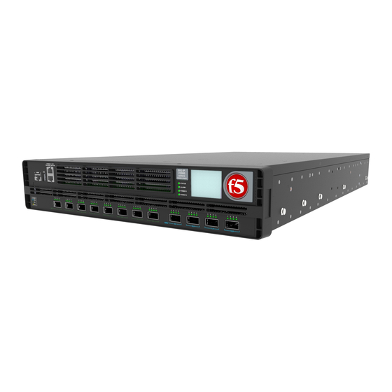
Platform Overview About i15000 Series models The i15000 Series platform is a powerful system that is designed specifically for application delivery performance and scalability. The i15000 Series platform is available in a Network Equipment-Building System (NEBS) compliant version (i15000-N). The i15000-N with stock DC power supply units (PSUs) is NEBS compliant. The i15000-N with AC PSU upgrades (UPGs) is not NEBS compliant. -
Page 6: Hardware Included With The Platform
7. Indicator LEDs 8. 2.2 inch LCD touchscreen The back of the i15000 Series platform includes the fan tray, two power supply units (PSUs), the chassis ground terminals, and the storage drives (located behind the fan tray). Figure 3: Back view of the i15000 Series AC-powered platform 1. -
Page 7: Peripheral Hardware Required
Setting Up the i15000 Series Platform Quantity Hardware RJ45 to RJ45 failover cable, CAT 5 crossover (blue) RJ45 to DB9 console port cable (beige) RJ45F to RJ45M rolled adapter (beige) Quick-install rail kit Rail lock brackets M3 x 8mm flathead screws, black with patch... -
Page 9: Platform Installation
Important: Before you install this platform, review the environmental guidelines to make sure that you are installing the platform into a compatible rack and in the appropriate environment. Note: F5 recommends that you keep all original packaging, in case you need to repackage and ship the platform later. -
Page 10: Install The Rail Lock Brackets
Platform Installation Quantity Hardware Quick-install rails #8-32 pan head screws, steel zinc #8-32 thumb screws (from rail kit) Rail lock brackets M3 x 8mm flathead screws, black with patch (threadlock) (for rail lock brackets) Install the rail lock brackets Be sure that the rails are installed onto the chassis before you install the rail lock brackets. The rail lock brackets secure the platform to the rack when you are using the quick-install rail kit. -
Page 11: About Installing The I15000-N (Nebs) Platform
Important: Before you install this platform, review the environmental guidelines to make sure that you are installing the platform into a compatible rack and in the appropriate environment. Note: F5 recommends that you keep all original packaging, in case you need to repackage and ship the platform later. -
Page 12: About Grounding The Platform
For this platform, F5 recommends using dual ring grounding lugs by Panduit (part number LCDX6-10AF-L). Important: All grounding cable terminal lugs must meet appropriate safety standards. -
Page 13: Connect The Ground Lug To The Ground Terminal
Setting Up the i15000 Series Platform Figure 6: Chassis ground lugs (with and without protective cap) Connect the ground lug to the ground terminal You must provide these components to properly ground the chassis: • Crimping tool • Dual ring ground terminal lug (for example, Panduit dual ring grounding lug, part number LCDX6-10AF-L) •... - Page 14 2. Connect the console port to a serial console server. Depending on which F5 system you have and the console network to which you are attaching, you can use either the supplied RJ45 to DB9 console port cable or the RJ45F to RJ45M rolled serial adapter to connect the system to a serial console.
-
Page 15: Configure A Management Ip Address Using The Lcd
This utility collects configuration and diagnostic information QKView about your system into a single file that you can provide to F5 Technical Support to aid in troubleshooting. For more information, see K12878: Generating diagnostic data using the qkview utility Configure a management IP address using the LCD You can use the touchscreen LCD to configure the management IP address. - Page 16 Platform Installation 4. Tap Management. The Management screen displays. 5. For the Type setting, tap to select either IPv4 or IPv6. 6. If you are using IPv4, you can configure the management IP address using DHCP: a) Tap DHCP. The DHCP option displays. b) Tap to set the DHCP option to ON.
- Page 17 Setting Up the i15000 Series Platform If you selected IPv6, this screen displays: d) Tap IP Address. The IP Address screen displays. e) Use the left, right, up, and down arrows to configure the management IP address and the length of the routing prefix for the IPv4 or IPv6 management IP address.
-
Page 18: License The Platform
If this is the first time you have accessed the Configuration utility, the first screen you see is the Introduction screen. 3. Click Next to view the License screen. 4. Follow the instructions in the Configuration utility to license the platform. For more information about licensing your platform, see BIG-IP System: Essentials at support.f5.com. -
Page 19: Environmental Guidelines
Environmental Guidelines General environmental and installation guidelines The i15000 Series platform is an industrial network appliance that is designed to be mounted in a standard 19-inch EIA rack. Follow these guidelines to adhere to safety precautions: • Install the rack according to the manufacturer's instructions and check the rack for stability before placing equipment in it. -
Page 20: Chassis Rack-Mount Spatial Requirements
Environmental Guidelines Chassis rack-mount spatial requirements The i15000 Series platforms ship with a rack mount kit to help install the system more easily. This kit requires that the rack or cabinet has certain clearances and spacing, as shown here. Figure 8: Rack mounting spatial requirements for the i15000 Series platform... -
Page 21: Guidelines For Power Supply Units (Psus)
Setting Up the i15000 Series Platform Figure 9: Detailed view of rack mounting spatial requirements Guidelines for power supply units (PSUs) All iSeries platforms support either single or dual power supply units (PSUs). When your system includes dual PSUs, both supplies must be of the same type. To verify this, make sure that the supplies have matching base part numbers (PWR-XXXX). -
Page 22: Guidelines For Ac-Powered Equipment
Environmental Guidelines When you add or replace a PSU in your system, be sure to verify the supply's features and that the PWR-XXXX part numbers match to ensure that you have the correct supply. Guidelines for AC-powered equipment An AC-powered installation must meet these requirements: •... -
Page 23: Guidelines For Nebs Platforms
Setting Up the i15000 Series Platform Guidelines for NEBS platforms This information applies to the Network Equipment-Building System (NEBS) version of the this platform: • This equipment meets NEBS requirements per GR-63-CORE. • This equipment is suitable for installation in these locations: •... - Page 24 Environmental Guidelines Figure 11: Airflow in iSeries platforms...
-
Page 25: Legal Notices
2021, F5, Inc. All rights reserved. F5, Inc. (F5) believes the information it furnishes to be accurate and reliable. However, F5 assumes no responsibility for the use of this information, nor any infringement of patents or other rights of third parties which may result from its use. - Page 27 Index Index AC-powered equipment hardware guidelines AC-powered equipment DC-powered equipment hardware requirements for peripherals hard-wired failover cables hubs connecting for failover for power CD/DVD-ROM drives support for i15000-N (NEBS) platform chassis securing ventilation indicator LEDs chassis ground lug location locating installation chassis ventilation guidelines...
- Page 28 Index platform (continued) redundancy ventilation for system platform airflow redundant system configuration diagram See also device service clustering (DSC). platform cooling remote administration diagram RJ45F to RJ45M rolled serial adapter platform photos platform ventilation diagram ports serial console location for hardware installation power cables hardware installation of connecting...
Need help?
Do you have a question about the i15000 Series and is the answer not in the manual?
Questions and answers