Table of Contents
Advertisement
Advertisement
Table of Contents

Related Manuals for F5 i5000 Series


Summary of Contents for F5 i5000 Series
- Page 1 Platform Guide: i5000/i7000/i10000/i11000 Series MAN-0633-05...
-
Page 3: Table Of Contents
Table of Contents Table of Contents Platform Overview........................5 About i5000/i7000/i10000/i11000 Series models...............5 About the platform......................5 Hardware included with the platform..................7 Peripheral hardware required.....................7 About LCD menus......................8 System menu......................8 Alerts menu......................8 Options menu......................8 Setup menu......................9 About using the LCD......................9 Rebooting the unit.................... - Page 4 Hardware specifications - i7000 Series................54 Hardware specifications - i10000 Series................55 Hardware specifications - i11000 Series................55 Environmental operating specifications................56 Power specifications - i5000 Series................. 56 Power specifications - i7000 Series................. 57 Power specifications - i10000 Series................57 Power specifications - i11000 Series................58 Safety requirements......................
-
Page 5: Platform Overview
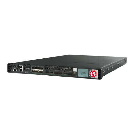
The i5000/i7000/i10000/i11000 Series platform is a powerful system that is designed specifically for application delivery performance and scalability. For more information, please see the data sheet at www.f5.com/pdf/products/big-ip-platforms- datasheet.pdf About the platform Before you install this platform, review information about the controls and ports located on both the front and back of the platform. - Page 6 6. 40GbE QSFP+ ports (46) 7. Indicator LEDs 8. 2.2 inch LCD touchscreen The back of the i5000 Series platform includes one power supply, one power blank, and a chassis ground terminal. Figure 5: Back view of the i5000 Series AC-powered platform 1.
-
Page 7: Hardware Included With The Platform
2 or 4 DC ring terminals, DC power only. By default, these platforms include one power supply and two ring terminals: i5000 Series. By default, these platforms include two power supplies and four ring terminals: i7000/i10000/i11000 Series. RJ45 to RJ45 failover cable, CAT 5 crossover (blue) -
Page 8: About Lcd Menus
Platform Overview Type of hardware Description unit. You should perform all installations and upgrades using the serial console, as these procedures require reboots, in which network connectivity is lost temporarily. Management workstation on You can use the default platform configuration if you have a the same IP network as the management workstation set up. -
Page 9: Setup Menu
Platform Guide: i5000/i7000/i10000/i11000 Series Option Description Display Adjusts LCD backlight brightness. Locator LED Controls the use of the chassis locator feature, which causes the F5 ® logo ball on the chassis front panel to flash on and off. Select from these options: •... -
Page 10: Rebooting The Unit
Platform Overview Rebooting the unit You can use the touchscreen LCD to perform a soft reboot of the unit. 1. Touch the screen to activate the LCD menus. 2. Tap System. The System screen displays. 3. On the System screen, tap Soft Reboot. 4. -
Page 11: Halt The Unit
Platform Guide: i5000/i7000/i10000/i11000 Series 3. On the System screen, tap Hard Reset. 4. Tap Confirm to reset the unit. Halt the unit You can use the touchscreen LCD to halt the unit. 1. Touch the screen to activate the LCD menus. 2. -
Page 12: Clear Alerts
Platform Overview 2. Tap System. The System screen displays. 3. On the System screen, swipe to scroll down and tap Power Off or Power On. 4. Tap Confirm to power off/on the unit. Clear alerts You can use the touchscreen LCD to clear alerts from the LCD. 1. -
Page 13: Configure Lcd Brightness
Platform Guide: i5000/i7000/i10000/i11000 Series 3. On the Alerts screen, clear either all alerts or alerts of a specific priority: • To clear all alerts, tap Clear All. • To clear only alerts of only a specific priority, tap the priority name to view alerts with that priority, and then tap Clear. -
Page 14: Enable/Disable The Chassis Locator Led
Platform Overview 4. Use the left and right arrows to adjust the brightness of the LCD in real-time. 5. Click Back to return to the previous screen. Enable/Disable the chassis locator LED You can use the touchscreen LCD to enable and disable the chassis locater LED. 1. -
Page 15: Alarm Led
Platform Guide: i5000/i7000/i10000/i11000 Series State Description off/none System is powered down. green solid System is running in normal mode. Also indicates that the system is in an Active state of a device group. amber solid System is running in an impaired mode or is operating in one of these conditions: •... -
Page 16: Ac Power Supply Leds
Platform Overview AC power supply LEDs The LEDs located on the AC power supplies indicate the operating state of the power supplies Input LED Output LED Condition green solid green solid Normal operation Fault: Input UV, Input OV, VSB SC amber solid Not valid green solid... -
Page 17: Define Custom Alerts
Each interface on the platform has a set of properties that you can configure, such as enabling or disabling the interface, setting the requested media type and duplex mode, and configuring flow control. ® For information about optical transceivers and cable pinouts for this platform, see F5 Platforms: Accessories. -
Page 18: About 40Gbe Qsfp+ Interfaces
Note: If you are using a breakout cable for 10GbE connectivity, you should use the supported distance as ® detailed in the Specifications for fiber QSFP+ modules section of the F5 Platforms: Accessories guide and not the Specifications for fiber SFP+ modules section. - Page 19 Platform Guide: i5000/i7000/i10000/i11000 Series 1. Open the Traffic Management Shell ( tmsh tmsh 2. Change to the network module. The system prompt updates with the module name: user@bigip01(Active)(/Common) (tmos.net)# user@bigiq01(Active)(/Common)(tmos.net)# 3. Display the current status of a specific interface. show interface <interface_key> This is an example of the output that you might see when you run this command on a specific interface: ----------------------------------------------------------------...
-
Page 20: About Interface Media Type And Duplex Mode
Platform Overview uninit none uninit none uninit none miss none uninit none uninit none uninit none uninit none miss none uninit none uninit none uninit none uninit none miss none uninit none uninit none uninit none uninit none mgmt 17.1G 19.0M 26.7M 31.0K... -
Page 21: About Network Interface Led Behavior
Platform Guide: i5000/i7000/i10000/i11000 Series 1. Open the Traffic Management Shell ( tmsh tmsh 2. Change to the network module. The system prompt updates with the module name: user@bigip01(Active)(/Common) (tmos.net)# user@bigiq01(Active)(/Common)(tmos.net)# 3. Display the valid media types for a specific interface. list interface <interface_key>... -
Page 22: About Always-On Management
Platform Overview State Description off (not lit) No link. amber solid Linked at 1/10GbE. amber blinking Link is actively transmitting or receiving data at 1/10GbE. SFP+ port 40GbE bundled LED behavior The appearance and behavior of the SFP+ port 40GbE bundled LEDs indicate network traffic activity, interface speed, and interface duplexity. -
Page 23: Accessing The Aom Command Menu From The Serial Console
Reset host Resets the host subsystem with a hardware reset. subsystem ® Important: F5 does not recommend using this option under normal circumstances. It does not allow for graceful shutdown of the system. Configure AOM Runs the AOM network configuration utility. This utility enables you to network reconfigure the IP address, netmask, and default gateway used by AOM. -
Page 24: Accessing The Aom Command Menu Using Ssh
Platform Overview 2. Open the AOM Command Menu. Esc ( 3. Type to open the AOM management network configurator. 4. Assign a management IP address, netmask, and gateway: • To use DHCP to assign the addresses, type when prompted about using DHCP. •... -
Page 25: Platform Installation
Platform Installation About installing the i5000/i7000/i10000/i11000 Series platform After you have reviewed the hardware requirements and become familiar with the i5000/i7000/i10000/ i11000 Series platform, you can install the unit into a 19-inch rack. Warning: Due to the weight of the platform, at least two people are required to install this chassis into a rack. -
Page 26: Install The Rail Lock Brackets
Platform Installation Quantity Hardware M3 x 8mm flathead screws, black with patch (for rail lock brackets) Install the rail lock brackets Be sure that the rails are installed onto the chassis before you install the rail lock brackets. The rail lock brackets secure the platform to the rack when you are using the quick-install rail kit. 1. -
Page 27: About Grounding The Platform
Platform Guide: i5000/i7000/i10000/i11000 Series About grounding the platform You must ground the platform after you install it in a rack. The chassis ground lug is located on the back of the platform. Do not secure multiple bonding or grounding connectors with the same bolt. The grounding connectors do not need to be removed to perform service or installation procedures. -
Page 28: Connect The Cables And Other Hardware
® 2. Connect the console port to a serial console server. Depending on which F5 system you have, you can use either the supplied RJ45 to DB9 console port cable or the RJ45F to RJ45M rolled serial adapter to connect the system to a serial console. -
Page 29: Configure A Management Ip Address Using The Lcd
Optionally, you should run the latest version of the qkview utility. This utility collects configuration and diagnostic information about your system into a single file that you can provide to F5 Technical Support to aid in troubleshooting. For more information, see: support.f5.com/kb/en-us/solutions/public/12000/800/sol12878.html... - Page 30 Platform Installation 3. Tap Setup. The Setup screen displays. 4. Tap Management. The Management screen displays. 5. For the Type setting, tap to select either IPv4 or IPv6. 6. If you are using IPv4, you can configure the management IP address using DHCP: a) Tap DHCP.
- Page 31 Platform Guide: i5000/i7000/i10000/i11000 Series The DHCP screen displays. b) Make sure that the DHCP option is set to OFF. If the DHCP option was set to ON, tap OFF, and then tap Commit to save the change. c) Tap Back to return to the Management screen. If you selected IPv4, this screen displays: If you selected IPv6, this screen displays: d) Tap IP Address.
-
Page 32: License The Platform
Once the management IP address is configured for the platform, you can use the Configuration utility to ® license the appropriate F5 software. 1. Using a Web browser, navigate to the management IP address that you assigned to the platform. -
Page 33: Platform Maintenance
Important: You should use only one power supply unit type (AC or DC) in a platform. AC and DC interoperability is not supported. ® Important: This product is sensitive to electrostatic discharge (ESD). F5 recommends that you use proper ESD grounding procedures and equipment when you install or maintain the unit. - Page 34 Platform Maintenance Figure 12: The 650W AC power supply Caution: As a safety precaution, the socket outlet must be installed near the equipment and be easily accessible. Replace an AC power supply in a single-supply system In the event of a power supply failure, you can replace an AC power supply in a single supply system. Caution: Be sure that you are using the correct wattage power supply when performing a power supply replacement.
- Page 35 Platform Guide: i5000/i7000/i10000/i11000 Series 3. Remove the failed AC PSU by squeezing the ejector latch and pulling straight toward you. Note: After you remove a power supply unit (PSU) from the system, ensure that the replacement PSU has been unpowered for 30 seconds to ensure that the PSU circuitry is fully discharged before inserting the replacement PSU into the system.
- Page 36 Platform Maintenance 5. Inspect the new PSU, especially the connector area, for any damage that might have occurred during shipment. 6. Slide the new PSU into the empty slot, and push it in until the ejector latch engages and clicks. Note: While installing the supply, use care to ensure that the supply's connector does not come into contact with the rear of the chassis.
- Page 37 Platform Guide: i5000/i7000/i10000/i11000 Series 1. Make sure that you have a live power supply unit (PSU) already installed in your system if you want to hot swap a PSU while the system is running. 2. Before removing the PSU from your system, disconnect the AC power cord from the power supply by pulling one or both of the power cord locking tabs away from the power supply.
-
Page 38: About Dc Power Supplies
Platform Maintenance 5. Inspect the new PSU, especially the connector area, for any damage that might have occurred during shipment. 6. Slide the new PSU into the empty slot, and push it in until the ejector latch engages and clicks. Note: While installing the supply, use care to ensure that the supply's connector does not come into contact with the rear of the chassis. - Page 39 Note: The battery return terminals on the platform are in an isolated DC return (DC-I) configuration. ® Note: When you are running a redundant DC power supply configuration, F5 strongly recommends that each DC power supply unit in the system receives power from independent DC main power sources with independent circuit breakers.
- Page 40 Platform Maintenance Replace a DC power supply in a single-supply system Before you perform a DC power supply unit (PSU) replacement, you need to provide these tools and components: • 12 AWG copper cable long enough to reach from the platform to the DC power source •...
- Page 41 Platform Guide: i5000/i7000/i10000/i11000 Series 10. If the chassis is not connected to Earth ground, connect the power supply Earth ground terminal to Earth ground. 11. After you have attached the ring terminals to the terminals, secure them using a screwdriver. Use 13.5 inch-pounds (1.53 Newton-meters) of torque on these screws.
- Page 42 Platform Maintenance 1. Make sure that you have a live power supply unit (PSU) already installed in your system if you want to hot swap a PSU while the system is running. 2. Be sure that the circuit breaker for the DC mains power source is switched off. 3.
-
Page 43: About The Fan Tray
Platform Guide: i5000/i7000/i10000/i11000 Series 14. Slide the new PSU into the empty slot, and push it in until the ejector latch engages and clicks. Note: While installing the supply, use care to ensure that the supply's connector does not come into contact with the rear of the chassis. -
Page 44: Replacing The Fan Tray
Platform Maintenance Figure 14: The i7000/i10000/i11000 Series fan tray ® Important: This product is sensitive to electrostatic discharge (ESD). F5 recommends that you use proper ESD grounding procedures and equipment when you install or maintain the unit. Replacing the fan tray To ensure that you can easily access the fan tray, route the power cords away from the fan tray so that the cords do not drape over or cross in front of it. -
Page 45: About Replacing A Drive In Single-Drive System
An F5 software ISO image • An F5 system or a Linux system that is used to create a bootable USB flash drive Replace a storage drive tray in a single-drive system You can remove the faulty drive from the chassis and install the blank replacement drive that you ®... - Page 46 Platform Maintenance 6. Slide the new drive tray into the empty drive bay until the latch engages the chassis. 7. Rotate the latch to the locking position by pushing it inward toward the chassis until the latch clicks. 8. Slide the fan tray back into the fan tray slot. 9.
-
Page 47: Environmental Guidelines
Failing to use two people can result in severe personal injury or equipment damage. ® Important: This product is sensitive to electrostatic discharge (ESD). F5 recommends that you use proper ESD grounding procedures and equipment when you install or maintain the unit. - Page 48 Environmental Guidelines Figure 15: Rack mounting spatial requirements for the i5000/i7000/i10000/i11000 Series platform...
-
Page 49: Guidelines For Ac-Powered Equipment
Platform Guide: i5000/i7000/i10000/i11000 Series Figure 16: Detailed view of rack mounting spatial requirements Guidelines for AC-powered equipment An AC-powered installation must meet these requirements: • Use a 15 amp external branch circuit protection device to install the unit. • Use one power feed for each individual power supply. Important: The platform must be installed in a RESTRICTED ACCESS LOCATION, such as a central office or customer premises environment. -
Page 50: Guidelines For Dc-Powered Equipment
Environmental Guidelines Note: High leakage current. Earth connection essential before connecting supply. Guidelines for DC-powered equipment A DC-powered installation must meet these requirements: • Use a 15 amp external branch circuit protection device to install the unit. • For permanently connected equipment, incorporate a readily accessible disconnect in the fixed wiring. •... - Page 51 Platform Guide: i5000/i7000/i10000/i11000 Series Figure 17: Airflow in iSeries platforms...
- Page 52 Environmental Guidelines...
-
Page 53: Platform Specifications
Security profile is available. TurboFlex Profiles are supported only in platforms running a high performance license (x800). Also, TurboFlex Profile availability varies depending on the platform series tier. Hardware specifications - i5000 Series This table lists hardware specifications for i5000 Series platforms. Item Specification Dimensions H: 1.72 inches (4.37 cm) x W: 17.4 inches (44.20 cm) x D: 30.6 inches (77.72... -
Page 54: Hardware Specifications - I7000 Series
Platform Specifications Item Specification 1 x RJ45 console port 1 x RJ45 failover port 1 x USB 2.0 interface Storage drive capacity 1 x 480 GB solid-state drive (SSD) 48 GB AC power supply 1 x 650 W 100-240 VAC(+/- 10%) AUTO Switching Platinum 1 x NEMA 5-15P power cords DC power supply 2 x 650W DC... -
Page 55: Hardware Specifications - I10000 Series
Platform Guide: i5000/i7000/i10000/i11000 Series Important: Specifications are subject to change without notification. Hardware specifications - i10000 Series This table lists hardware specifications for i10000 Series platforms. Item Specification Dimensions H: 1.72 inches (4.37 cm) x W: 17.4 inches (44.20 cm) x D: 30.6 inches (77.72 cm) (per unit) 1U industry standard rack-mount chassis Weight 36.0 pounds (16.33 kg) with two power supplies (per unit) -
Page 56: Environmental Operating Specifications
-40 to 158°F (-40 to 70°C) temperature Non-operational relative 5% to 93% (40°C) non-condensing humidity Power specifications - i5000 Series This table lists power specifications for i5000 Series platforms. Item Single power supply Dual power supply Idle power draw (AC power) 110VAC input: 195W... -
Page 57: Power Specifications - I7000 Series
Platform Guide: i5000/i7000/i10000/i11000 Series Item Single power supply Dual power supply Typical heat generated (AC power) 110VAC input: 905 BTU/ 110VAC input: 905 BTU/ hour hour 220VAC input: 890 BTU/ 220VAC input: 905 BTU/ hour hour Typical heat generated (DC power) 48VDC input: 890 BTU/ 48VDC input: 905 BTU/ hour... -
Page 58: Power Specifications - I11000 Series
Platform Specifications Item Single power supply Dual power supply Typical power draw (AC power; 50% load; 110VAC input: 405W 110VAC input: 415W temp 25°C) 220VAC input: 400W 220VAC input: 410W Typical power draw (DC power; 50% load; 48VDC input: 400W 48VDC input: 405W temp 25°C) Maximum power draw (AC power) -
Page 59: Emc Requirements
Platform Guide: i5000/i7000/i10000/i11000 Series EN 60950-1:2006+A11:2009+A1:2010+A12:2011+A2:2013 IEC 60950-1:2005, A1:2009+A2:2013 CSA 60950-1-07, Including A1:2011+A2:2014 ANSI/UL 60950-1-2014 EMC requirements USA--FCC Class A, Canada--Industry Canada Class A This equipment complies with Part 15 of FCC Rules. Operation is subject to these two conditions: 1. -
Page 60: Airflow Specifications
Platform Specifications Airflow specifications This table lists airflow movement specifications for BIG-IP ® iSeries platforms. Note: Fan tray airflow measurements are taken at 100% duty cycle and in open air. Platform Value (max) i5000 97 CFM i7000/i10000/i11000 146 CFM Restriction of Hazardous Substances Directive (RoHS) for China Products listed on this declaration comply with the Restriction of Hazardous Substances (RoHS) directive 2011/65/EU, and produce required technical documentation in compliance with EN50581:2012. - Page 61 Platform Guide: i5000/i7000/i10000/i11000 Series...
- Page 62 Platform Specifications...
-
Page 63: Repackaging Guidelines
You can perform a disk erase operation to erase all sensitive data from storage drives (for example, solid- ® state drives and hard disk drives) before you return a platform to F5. For more information, see F5 Platforms: Essentials. Important: Before returning any equipment, contact F5 to obtain a Service Order (SO) or Return Material Authorization (RMA) case number. - Page 64 Repackaging Guidelines...
-
Page 65: Returned Material Data Security Statement
Returned Material Data Security Statement About returned material data security ® Follow these data security guidelines when returning equipment to F5 for reprocessing or repair. The guidelines include reprocessing procedures and optional customer-end procedures. About memory technologies used in F5 equipment ®... -
Page 66: About Removing Data From F5 Components
For components that contain sensitive customer data and cannot be removed from your F5 system, you can take optional steps to remove the data from these components before you return the system to F5 for processing. Removing sensitive data from storage drives ®... -
Page 67: Legal Notices
2017, F5 Networks, Inc. All rights reserved. F5 Networks, Inc. (F5) believes the information it furnishes to be accurate and reliable. However, F5 assumes no responsibility for the use of this information, nor any infringement of patents or other rights of third parties which may result from its use. - Page 68 Legal Notices Any modifications to this device, unless expressly approved by the manufacturer, can void the user's authority to operate this equipment under part 15 of the FCC rules. Canadian Regulatory Compliance This Class A digital apparatus complies with Canadian ICES-003. Standards Compliance This product conforms to the IEC, European Union, ANSI/UL and Canadian CSA standards applicable to Information Technology products at the time of manufacture.
- Page 69 Index Index chassis power LEDs 40G interfaces, See QSFP+ interfaces. chassis ventilation 40GbE interfaces, See QSFP+ interfaces. diagram China material content listing, See China RoHS Directive standards. China RoHS Directive standards AC power supplies Configuration utility and hot swapping licensing the platform AC-powered equipment managing interfaces guidelines...
- Page 70 LEDs for i10000 Series platforms about for i11000 Series platforms alarm for i5000 Series platforms chassis power for i7000 Series platforms defining custom alerts hazardous substance restrictions, See China RoHS Directive power supply, AC standards. power supply, DC...
- Page 71 53–55 reboot operation for solid-state drive 53–55 rebooting the unit power for i10000 Series platforms using the LCD power for i5000 Series platforms redundancy platform ventilation for system diagram redundant system configuration ports remote administration power cables...
- Page 72 53–55 for solid-state drive 53–55 for system features power for i10000 Series platforms power for i5000 Series platforms status LED storage drives about drive options about replacement in single-drive systems disk erase operation preparing to replace a single drive...
Need help?
Do you have a question about the i5000 Series and is the answer not in the manual?
Questions and answers