Table of Contents
Advertisement
Quick Links
TForce 550 SE Setup Manual
FCC Information and Copyright
This equipment has been tested and found to comply with the limits of a Class
B digital device, pursuant to Part 15 of the FCC Rules. These limits are designed
to provide reasonable protection against harmful interference in a residential
installation. This equipment generates, uses and can radiate radio frequency
energy and, if not installed and used in accordance with the instructions, may
cause harmful interference to radio communications. There is no guarantee
that interference will not occur in a particular installation.
The vendor makes no representations or warranties with respect to the
contents here and specially disclaims any implied warranties of merchantability
or fitness for any purpose. Further the vendor reserves the right to revise this
publication and to make changes to the contents here without obligation to
notify any party beforehand.
Duplication of this publication, in part or in whole, is not allowed without first
obtaining the vendor's approval in writing.
The content of this user's manual is subject to be changed without notice and
we will not be responsible for any mistakes found in this user's manual. All the
brand and product names are trademarks of their respective companies.
Advertisement
Chapters
Table of Contents

Related Manuals for Biostar TForce 550 SE


Summary of Contents for Biostar TForce 550 SE
- Page 1 TForce 550 SE Setup Manual FCC Information and Copyright This equipment has been tested and found to comply with the limits of a Class B digital device, pursuant to Part 15 of the FCC Rules. These limits are designed to provide reasonable protection against harmful interference in a residential installation.
-
Page 2: Table Of Contents
Table of Contents Chapter 1: Introduction ........1 Before You Start ................1 Package Checklist ................1 Motherboard Features..............2 Rear Panel Connectors (Ver 5.x)............. 4 Rear Panel Connectors (Ver 6.x)............. 4 Motherboard Layout (Ver 5.x)............5 Motherboard Layout (Ver 6.x)............6 Chapter 2: Hardware Installation ...... -
Page 3: Chapter 1: Introduction
TForce 550 SE CHAPTER 1: INTRODUCTION EFORE TART Thank you for choosing our product. Before you start installing the motherboard, please make sure you follow the instructions below: Prepare a dry and stable working environment with sufficient lighting. Always disconnect the computer from power outlet before operation. -
Page 4: Motherboard Features
Motherboard Manual OTHERBOARD EATURES Ver 5.x Ver 6.x Socket AM2 Socket AM2 AMD Athlon 64 / Athlon 64 FX / Athlon 64 x2 / AMD Athlon 64 / Athlon 64 FX / Athlon 64 x2 / Sempron processors Sempron processors AMD 64 Architecture enables 32 and 64 bit AMD 64 Architecture enables 32 and 64 bit computing... - Page 5 Windows 2K / XP / VISTA Windows 2K / XP / VISTA OS Support Biostar Reserves the right to add or remove Biostar Reserves the right to add or remove support for any OS With or without notice. support for any OS With or without notice.
-
Page 6: Rear Panel Connectors (Ver 5.X)
Motherboard Manual ANEL ONNECTORS PS/2 Mouse PS/2 COM1 USBX2 USBX2 USBX2 Keyboard Center Line In Rear Line Out Side Mic In ANEL ONNECTORS PS/2 Mouse Line In/ Surround Line Out Mic In 1/ Bass/ Center PS/2 COM1 USBX2 USBX2 USBX2 Keyboard... -
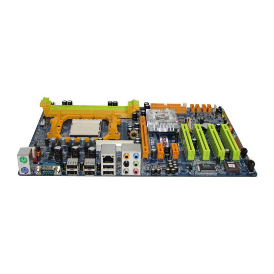
Page 7: Motherboard Layout (Ver 5.X)
TForce 550 SE OTHERBOARD AYOUT JCFAN1 JKBMSV1 JKBMS1 JA TXPWR2 JUSB3 JUSBV2 JUSB4 JATXPWR1 JUSBLAN1 JAUDIO1 PEX16_1 PEX1_1 Codec nForce 550 PEX1_2 PCI1 JNFAN1 Super I/O JSFAN2 PCI2 JSATA4 JCI1 JCMOS1 JSATA3 BAT1 PCI3 JSATA2 BIOS JSATA1 PCI4 JSFAN1 JUSBV1... -
Page 8: Motherboard Layout (Ver 6.X)
Motherboard Manual OTHERBOARD AYOUT JCFAN1 JKBMSV1 JKBMS1 JA TXPWR2 JUSB3 JUSBV2 JUSB4 JATXPWR1 JUSBLAN1 JAUDIO1 PEX16_1 PEX1_1 Codec nForce 550 PEX1_2 PCI1 JNFAN1 Super I/O JSFAN2 PCI2 JSATA4 JCI1 JCMOS1 JSATA3 BAT1 PCI3 JSATA2 BIOS JSATA1 PCI4 JSFAN1 JUSBV1 JAUDIOF1 JSPDIF_OUT JPRNT1 RSTSW1... -
Page 9: Chapter 2: Hardware Installation
TForce 550 SE CHAPTER 2: HARDWARE INSTALLATION (CPU) NSTALLING ENTRAL ROCESSING Step 1: Remove the socket protection cap. Step 2: Pull the lever toward direction A from the socket and then raise the lever up to a 90-degree angle. Step 3: Look for the white triangle on socket, and the gold triangle on CPU should point forwards this white triangle. - Page 10 Motherboard Manual Step 4: Hold the CPU down firmly, and then close the lever toward direct B to complete the installation. Step 5: Put the CPU Fan on the CPU and buckle it. Connect the CPU FAN power cable to the JCFAN1. This completes the installation.
-
Page 11: Fan Headers
TForce 550 SE FAN H EADERS These fan headers support cooling-fans built in the computer. The fan cable and connector may be different according to the fan manufacturer. Connect the fan cable to the connector while matching the black wire to pin#1. -
Page 12: Installing System Memory
Motherboard Manual NSTALLING YSTEM EMORY Unlock a DIMM slot by pressing the retaining clips outward. Align a DIMM on the slot such that the notch on the DIMM matches the break on the Slot. Insert the DIMM vertically and firmly into the slot until the retaining chip snap back in place and the DIMM is properly seated. - Page 13 TForce 550 SE C. Dual Channel Memory installation To trigger the Dual Channel function of the motherboard, the memory module must meet the following requirements: Install memory module of the same density in pairs, shown in the following table. Duual Channel Status DDR2A1...
-
Page 14: Connectors And Slots
Motherboard Manual ONNECTORS AND LOTS FDD1: Floppy Disk Connector The motherboard provides a standard floppy disk connector that supports 360K, 720K, 1.2M, 1.44M and 2.88M floppy disk types. This connector supports the provided floppy drive ribbon cables. IDE1: Hard Disk Connectors The motherboard has a 32-bit Enhanced PCI IDE Controller that provides PIO Mode 0~4, Bus Master, and Ultra DMA 33/66/100/133 functionality. - Page 15 TForce 550 SE PEx16-1: PCI-Express x16 Slot PCI-Express 1.0a compliant. Maximum theoretical realized bandwidth of 4GB/s simultaneously per direction, for an aggregate of 8GB/s totally. PEx1_1/PEx1_2: PCI-Express x1 slots PCI-Express 1.0a compliant. Data transfer bandwidth up to 250MB/s per direction; 500MB/s in total.
-
Page 16: Chapter 3: Headers & Jumpers Setup
Motherboard Manual CHAPTER 3: HEADERS & JUMPERS SETUP OW TO ETUP UMPERS The illustration shows how to set up jumpers. When the jumper cap is placed on pins, the jumper is “close”, if not, that means the jumper is “open”. Pin opened Pin closed Pin1-2 closed... - Page 17 TForce 550 SE JATXPWR1: ATX Power Source Connector This connector allows user to connect 24-pin power connector on the ATX power supply. Assignment +3.3V +3.3V Ground Ground Ground PW_OK Standby Voltage +5V +12V +12V +3.3V +3.3V -12V Ground PS-ON Ground...
- Page 18 Motherboard Manual JUSB1/JUSB2: Headers for USB 2.0 Ports at Front Panel This header allows user to connect additional USB cable on the PC front panel, and also can be connected with internal USB devices, like USB card reader. Assignment +5V (fused) +5V (fused) USB- USB-...
- Page 19 TForce 550 SE JAUDIOF1: Front Panel Audio Header This header allows user to connect the front audio output cable with the PC front panel. It will disable the output on back panel audio connectors. Assignment Mic Left in Ground Mic Right in...
-
Page 20: Clear Cmos Procedures
Motherboard Manual JCMOS1: Clear CMOS Header By placing the jumper on pin2-3, it allows user to restore the BIOS safe setting and the CMOS data, please carefully follow the procedures to avoid damaging the motherboard. Pin 1-2 Close: Normal Operation (default). - Page 21 TForce 550 SE JSATA1~JSATA4: Serial ATA Connectors The motherboard has a PCI to SATA Controller with 4 channels SATA interface, it satisfies the SATA 2.0 spec and with transfer rate of 3.0Gb/s. Assignment Ground Ground SATA4 SATA3 Ground SATA2 SATA1 JSPDIF_OUT: Digital Audio out Connectors This connector allows user to connect the PCI bracket SPDIF output header.
- Page 22 Motherboard Manual JPRNT1: Printer Port Connector This header allows you to connector printer on the PC. Assignment Assignment -Strobe Ground -ALF Data 6 Data 0 Ground -Error Data 7 Data 1 Ground -Init -ACK Data 2 Ground -Scltin Busy Data 3 Ground Ground Data 4...
- Page 23 TForce 550 SE JDDRII_2.4V : Header for Memory Voltage Overclocking When processing Memory Voltage Overclocking, please place the jumper to pin1-2 Closed. The Default setting is Pin 2-3 Closed. Pin 1-2 Close: Normal status (default). Pin 2-3 Close: Memory voltage Overclocking.
- Page 24 Motherboard Manual On-Board LED Indicators There are 2 LED indicators on the motherboard to show system status. LED1 LED2 LED1 and LED2: These 2 LED indicate system power on diagnostics. Please refer to the table below for different messages: LED1 LED2 Message Normal...
-
Page 25: Chapter 4: Nvidia Raid Functions
TForce 550 SE CHAPTER 4: NVIDIA RAID FUNCTIONS PERATION YSTEM Supports Windows XP Home/Professional Edition, and Windows 2000 Professional. RRAYS NVRAID supports the following types of RAID arrays: RAID 0: RAID 0 defines a disk striping scheme that improves disk read and write times for many applications. - Page 26 Motherboard Manual RAID 1: Every read and write is actually carried out in parallel across 2 disk drives in a RAID 1 array system. The mirrored (backup) copy of the data can reside on the same disk or on a second redundant drive in the array. RAID 1 provides a hot-standby copy of data if the active volume or drive is corrupted or becomes unavailable because of a hardware failure.
- Page 27 TForce 550 SE RAID 0+1: RAID 0 drives can be mirrored using RAID 1 techniques. Resulting in a RAID 0+1 solution for improved performance plus resiliency. Features and Benefits Drives: Minimum 4, and maximum is 6 or 8, depending on the platform.
-
Page 28: Chapter 5: Overclock Quick Guide
CHAPTER 5: OVERCLOCK QUICK GUIDE OWER NTRODUCTION Biostar T-Power is a whole new utility that is designed for overclock users. Based on many precise tests, Biostar Engineering Team (BET) has developed this ultimate overclock engine to raise system performance. No matter whether under BIOS or Windows interface, T-Power is able to present the best system state according to users’... -
Page 29: T-Power Bios Feature
TForce 550 SE BIOS F OWER EATURE A. Overclocking Navigator Engine (O.N.E.): ONE provides two powerful overclocking engines: MOS and AOS for both Elite and Casual overclockers. Manual Overclock System (M.O.S.) MOS is designed for experienced overclock users. It allows users to customize personal overclock settings. - Page 30 Motherboard Manual CPU Overclock Setting: CPU Voltage: This function will increase CPU stability when overclocking. However, the CPU temperature will increase when CPU voltage is increased. Choices: The adjustable range is from 0.800V to 2.310V. CPU Frequency: CPU Frequency is directly in proportion to system performance. To maintain the system stability, CPU voltage needs to be increased also when raising CPU frequency.
- Page 31 TForce 550 SE Automatic Overclock System (A.O.S.) For beginners in overclock field, BET had developed an easy, fast, and powerful feature to increase the system performance, named A.O.S. Based on many tests and experiments, A.O.S. provides 3 ideal overclock configurations that are able to raise the system performance in a single step.
- Page 32 Motherboard Manual V12 Tech Engine: This setting will raise about 25%~30% of whole system performance. Notices: Not all types of AMD CPU perform above overclock setting ideally; the difference will be based on the selected CPU model. From BET experiments, the Atholon64 FX CPU is not suitable for this A.O.S. feature. B.
- Page 33 TForce 550 SE C. Memory Integration Test (M.I.T.): This function is under “Overclocking Navigator Engine” item. MIT allows users to test memory compatibilities, and no extra devices or software are needed. Step 1: The default setting under this item is “Disabled”; the condition parameter should be changed to “Enable”...
- Page 34 E. Integrated Flash Program (I.F.P.): IFP is a safe and quick way to upgrade BIOS. Step 1: Go to Biostar website (http://www.biostar.com.tw) to download the latest BIOS file. Then, save the file into a floppy disk. Step 2: Insert the floppy disk and reboot the system to get into CMOS screen.
- Page 35 TForce 550 SE F. Smart Fan Function: Smart Fan Function is under “PC Health Status”. This is a brilliant feature to control CPU Temperature vs. Fan speed. When enabling Smart Fan function, Fan speed is controlled automatically by CPU temperature.
- Page 36 Motherboard Manual Start PWM Value When CPU temperature arrives to the set value, the CPU fan will work under Smart Fan Function mode. The range is from 0~127, with an interval of 1. Slope PWM Choices: 1 PWM Value/℃ (default), 2 PWM Value/℃, 4 PWM Value/℃, 8 PWM Value/℃, 16 PWM Value/℃, 32 PWM Value/℃, 64PWM Value/℃.
-
Page 37: T-Power Windows Feature
TForce 550 SE OWER INDOWS EATURE A.Hardware Monitor: T-Power Hardware monitor allows users to monitor system voltage, temperature and fan speed accordingly. Additionally, a rescue action will be taken by the program automatically while the system faces an abnormal condition. The program will trigger an alarm or shut down the system when unpredictable errors occur. -
Page 38: Cpu Temperature
Motherboard Manual CPU Temperature This column configures the CPU temperature. There is a waveform to represent the status of CPU temperature. By adjusting , users can easily configure the upper limit of CPU temperature for system operating. In this diagram, the white line represents the upper limit which user-set for CPU temperature and the green line shows present CPU temperature. - Page 39 TForce 550 SE CPU/Battery Voltage VCore This item displays the CPU voltage, represented by a light blue line. Users can set the upper and lower limit by adjusting to monitor the CPU operating voltage. If CPU voltage is higher or lower than the set value, the status line will change into a red warning line, and a warning sound will alert you.
- Page 40 Graphic 1 will appear when activating this utility. Graphic 1 Clicking on “Biostar” will lead you to the Biostar Homepage. This column shows the CPU speed information. C. Click on this button and the utility will pop-up 4 sub-screens (Please refers to Graphic 3).
- Page 41 TForce 550 SE CPU Overclocking Settings: By adjusting can configure three items for CPU overclocking. CPU Frequency Range: 133MHz~450MHz. Interval: 1MHz. CPU Ratio Range: 4~25. Interval: 1. CPU Voltage Range: 1.175V~1.725V. Interval: 0.025V. Memory Overclocking Settings: By adjusting can configure two items for Memory overclocking.
- Page 42 Motherboard Manual PCI Overclocking Setting: This diagram shows present PCI working status and helps to monitor PCI peripherals working status. This item cannot be adjusted.
- Page 43 TForce 550 SE C. Smart Fan Function When Smart Fan Function is activated, screens will pop-up to illustrate the fan speed information. CPU Temperature: Show current CPU temperature. CPU Fan speed: Show current CPU Fan speed. iii. System Fan speed: Show current system Fan speed.
- Page 44 Motherboard Manual Auto: If the green indicator is lit up, the Smart Fan Function is “On” (Default Setting). Click on this button again to close Smart Fan Function, and a screen as below would pop-up. There will be pulling-meter besides the CPU Fan and System Fan, the CPU Fan and the System Fan speed can be adjusted by adjusting the Cursor Up or Down.
- Page 45 When Live Update program is activated, a screen will pop up to illustrate BIOS related information. Link to Internet: Click on this button will link to Biostar website and BIOS file will be downloaded. Update BIOS: Click on this button to run BIOS flashing process, and it’s easy and safe.
-
Page 46: Chapter 6: Useful Help
Motherboard Manual CHAPTER 6: USEFUL HELP RIVER NSTALLATION After you installed your operating system, please insert the Fully Setup Driver CD into your optical drive and install the driver for better system performance. You will see the following window after you insert the CD The setup guide will auto detect your motherboard and operating system. -
Page 47: Award Bios Beep Code
BIOS contents are corrupted. In this Case, please follow the procedure below to restore the BIOS: 1. Make a bootable floppy disk. 2. Download the Flash Utility “AWDFLASH.exe” from the Biostar website: www.biostar.com.tw 3. Confirm motherboard model and download the respectively BIOS from Biostar website. - Page 48 Motherboard Manual B. CPU Overheated If the system shutdown automatically after power on system for seconds, that means the CPU protection function has been activated. When the CPU is over heated, the motherboard will shutdown automatically to avoid a damage of the CPU, and the system may not power on again.
-
Page 49: Troubleshooting
TForce 550 SE 6.4 T ROUBLESHOOTING Probable Solution No power to the system at all Make sure power cable is Power light don’t illuminate, fan securely plugged in. inside power supply does not turn Replace cable. Contact technical support. Indicator light on keyboard does not turn on. -
Page 50: Appendencies: Spec In Other Language
Motherboard Manual APPENDENCIES: SPEC IN OTHER LANGUAGE ERMAN Ver 5.x Ver 6.x Sockel AM2 Sockel AM2 AMD Athlon 64 / Athlon 64 FX / Athlon 64 x2 / AMD Athlon 64 / Athlon 64 FX / Athlon 64 x2 / Sempron Prozessoren Sempron Prozessoren Die AMD 64-Architektur unterstützt eine 32-Bit-... - Page 51 Unterstützt RAID 0 / 1 / 0+1 Windows 2K / XP / VISTA Windows 2K / XP / VISTA Biostar behält sich das Recht vor , ohne Biostar behält sich das Recht vor , ohne OS-Unterstüt Ankündigung die Unterstützung für ein Ankündigung die Unterstützung für ein...
-
Page 52: France
Motherboard Manual RANCE Ver 5.x Ver 6.x Socket AM2 Socket AM2 Processeurs AMD Athlon 64 / Athlon 64 FX / Processeurs AMD Athlon 64 / Athlon 64 FX / Athlon 64 x2 / Sempron Athlon 64 x2 / Sempron L'architecture AMD 64 permet le calcul 32 et 64 L'architecture AMD 64 permet le calcul 32 et 64 bits bits... - Page 53 Windows 2K / XP / VISTA Windows 2K / XP / VISTA Support SE Biostar se réserve le droit d'ajouter ou de Biostar se réserve le droit d'ajouter ou de supprimer le support de SE avec ou sans préavis. supprimer le support de SE avec ou sans préavis.
-
Page 54: Italian
Motherboard Manual TALIAN Ver 5.x Ver 6.x Socket AM2 Socket AM2 Processori AMD Athlon 64 / Athlon 64 FX / Processori AMD Athlon 64 / Athlon 64 FX / Athlon 64 x2 / Sempron Athlon 64 x2 / Sempron L’architettura AMD 64 abilita la L’architettura AMD 64 abilita la computazione 32 e 64 bit computazione 32 e 64 bit... - Page 55 Windows 2K / XP / VISTA Windows 2K / XP / VISTA Sistemi Biostar si riserva il diritto di aggiungere o Biostar si riserva il diritto di aggiungere o operativi rimuovere il supporto di qualsiasi sistema rimuovere il supporto di qualsiasi sistema supportati operativo senza preavviso.
-
Page 56: Spanish
Motherboard Manual PANISH Ver 5.x Ver 6.x Conector AM2 Conector AM2 Procesadores AMD Athlon 64 / Athlon 64 FX / Procesadores AMD Athlon 64 / Athlon 64 FX / Athlon 64 x2 / Sempron Athlon 64 x2 / Sempron La arquitectura AMD 64 permite el procesado de La arquitectura AMD 64 permite el procesado de 32 y 64 bits 32 y 64 bits... - Page 57 Windows 2K / XP / VISTA Windows 2K / XP / VISTA sistema Biostar se reserva el derecho de añadir o retirar Biostar se reserva el derecho de añadir o retirar operativo el soporte de cualquier SO con o sin aviso previo.
-
Page 58: Portuguese
Motherboard Manual ORTUGUESE Ver 5.x Ver 6.x Socket AM2 Socket AM2 Processadores AMD Athlon 64 / Athlon 64 FX / Processadores AMD Athlon 64 / Athlon 64 FX / Athlon 64 x2 / Sempron Athlon 64 x2 / Sempron A arquitectura AMD 64 permite uma computação A arquitectura AMD 64 permite uma computação de 32 e 64 bits de 32 e 64 bits... - Page 59 Windows 2K / XP / VISTA Windows 2K / XP / VISTA Sistemas A Biostar reserva-se o direito de adicionar ou A Biostar reserva-se o direito de adicionar ou operativos remover suporte para qualquer sistema remover suporte para qualquer sistema suportados operativo com ou sem aviso prévio.
-
Page 60: Polish
Motherboard Manual OLISH Ver 5.x Ver 6.x Socket AM2 Socket AM2 AMD Athlon 64 / Athlon 64 FX / Athlon 64 x2 / AMD Athlon 64 / Athlon 64 FX / Athlon 64 x2 / Sempron Procesory Sempron Procesory Procesor Architektura AMD 64 umożliwia przetwarzanie Architektura AMD 64 umożliwia przetwarzanie 32 i 64 bitowe... - Page 61 Obsługa RAID 0 / 1 / 0+1 Obsluga Windows 2K / XP / VISTA Windows 2K / XP / VISTA systemu Biostar zastrzega sobie prawo dodawania lub Biostar zastrzega sobie prawo dodawania lub operacyjne odwoływania obsługi dowolnego systemu odwoływania obsługi dowolnego systemu operacyjnego bez powiadomienia.
-
Page 62: Russian
Motherboard Manual USSIAN Ver 5.x Ver 6.x Гнездо AM2 Гнездо AM2 Процессоры AMD Athlon 64 / Athlon 64 FX / Процессоры AMD Athlon 64 / Athlon 64 FX / (центральн Athlon 64 x2 / Sempron Athlon 64 x2 / Sempron ый... - Page 63 тики Windows 2K / XP / VISTA Windows 2K / XP / VISTA Поддержка Biostar сохраняет за собой право добавлять Biostar сохраняет за собой право добавлять или удалять средства обеспечения для OS с или удалять средства обеспечения для OS с...
-
Page 64: Arabic
Motherboard Manual RABIC Ver 6.x Ver 5.x ﻡﻘﺒﺲAM2 ﻡﻘﺒﺲAM2 ﻡﻌﺎﻟﺠﺎتAMD Athlon 64 / Athlon 64 FX / ﻡﻌﺎﻟﺠﺎتAMD Athlon 64 / Athlon 64 FX / وﺣﺪة اﻟﻤﻌﺎﻟﺠﺔ Athlon 64 x2 / Sempron Athlon 64 x2 / Sempron اﻟﻤﺮآﺰﻳﺔ ﺗﻤﻜﻦ ﺗﻘﻨﻴﺔAMD 64 ﺗﻤﻜﻦ... -
Page 65: Pci Express X16
Windows 2K / XP / VISTA Windows 2K / XP / VISTA ﺗﺤﺘﻔﻆBiostar ﺎم ﺗﺸﻐﻴﻞ ﺏﺈﺥﻄﺎر أو ﺏﺤﻘﻬﺎ ﻓﻲ إﺿﺎﻓﺔ أو إزاﻟﺔ اﻟﺪﻋﻢ ﻷي ﻥﻈ ﺗﺤﺘﻔﻆBiostar ﺏﺤﻘﻬﺎ ﻓﻲ إﺿﺎﻓﺔ أو إزاﻟﺔ اﻟﺪﻋﻢ ﻷي ﻥﻈﺎم ﺗﺸﻐﻴﻞ ﺏﺈﺥﻄﺎر أو دﻋﻢ أﻥﻈﻤﺔ اﻟﺘﺸﻐﻴﻞ ﺏﺪون إﺥﻄﺎر ﺏﺪون إﺥﻄﺎر... -
Page 66: Japanese
Motherboard Manual APANESE Ver 5.x Ver 6.x Socket AM2 Socket AM2 AMD Athlon 64 / Athlon 64 FX / Athlon 64 x2 / AMD Athlon 64 / Athlon 64 FX / Athlon 64 x2 / Sempron プロセッサ Sempron プロセッサ AMD 64アーキテクチャでは、32ビットと64ビット計 AMD 64アーキテクチャでは、32ビットと64ビット計... - Page 67 TForce 550 SE Ver 5.x Ver 6.x ALC 888 ALC 861VD サウンド 7.1チャンネルオーディオアウト 5.1チャンネルオーディオアウト Codec ハイデフィニションオーディオのサポート ハイデフィニションオーディオのサポート PCIスロット PCIスロット PCI Express x16スロット PCI Express x16スロット スロット PCI Express x 1スロット PCI Express x 1スロット フロッピーコネクタ フロッピーコネクタ プリンタポートコネクタ プリンタポートコネクタ IDEコネクタ IDEコネクタ...
- Page 68 TForce 550 SE BIOS Setup ....................1 1 Main Menu ..................... 3 2 Standard CMOS Features..............7 3Advanced BIOS Features ............... 9 4 Advanced Chipset Features..............16 5 Integrated Peripherals................. 18 6 Power Management Setup ..............24 7 PnP/PCI Configurations..............28 8 PC Health Status ..................
-
Page 69: Bios Setup
TForce 550 SE BIOS Setup Introduction The purpose of this manual is to describe the settings in the Award™ BIOS Setup program on this motherboard. The Setup program allows users to modify the basic system configuration and save these settings to CMOS RAM. The power of CMOS RAM is supplied by a battery so that it retains the Setup information when the power is turned off. -
Page 70: Pci Bus Support
TForce 550 SE PCI Bus Support This AWARD BIOS also supports Version 2.1 of the Intel PCI (Peripheral Component Interconnect) local bus specification. DRAM Support DDR SDRAM (Double Data Rate Synchronous DRAM) is supported. Supported CPUs This AWARD BIOS supports the AMD CPU. -
Page 71: Main Menu
TForce 550 SE 1 Main Menu Once you enter Award BIOS™ CMOS Setup Utility, the Main Menu will appear on the screen. The Main Menu allows you to select from several setup functions. Use the arrow keys to select among the items and press <Enter> to accept and enter the sub-menu. -
Page 72: Load Optimized Defaults
TForce 550 SE Advanced Chipset Features This submenu allows you to configure special chipset features. Integrated Peripherals This submenu allows you to configure certain IDE hard drive options and Programmed Input/ Output features. Power Management Setup This submenu allows you to configure the power management features. -
Page 73: Set Supervisor Password
TForce 550 SE Set Supervisor Password Setting the supervisor password will prohibit everyone except the supervisor from making changes using the CMOS Setup Utility. You will be prompted with to enter a password. Set User Password If the Supervisor Password is not set, then the User Password will function in the same way as the Supervisor Password. - Page 74 TForce 550 SE Integrate Flashing Program This is a very safe way to upgrade BIOS. By pressing “Enter” key for three times, and the upgrading process will be completed easily.
-
Page 75: Standard Cmos Features
TForce 550 SE 2 Standard CMOS Features The items in Standard CMOS Setup Menu are divided into several categories. Each category includes no, one or more than one setup items. Use the arrow keys to highlight the item and then use the<PgUp> or <PgDn> keys to select the value you want in each item. - Page 76 TForce 550 SE Item Options Description 720K, 3.5 in 1.44M, 3.5 in 2.88M, 3.5 in None All Errors Select the situation in which No Errors you want the BIOS to stop Halt On All, but Keyboard the POST process and All, but Diskette notify you.
-
Page 77: 3Advanced Bios Features
TForce 550 SE 3Advanced BIOS Features Figure 3: Advanced BIOS Setup Cache Setup... - Page 78 TForce 550 SE CPU Internal Cache Depending on the CPU/chipset in use, you may be able to increase memory access time with this option. Enabled (default) Enable cache. Disabled Disable cache. External Cache This option enables or disables “Level 2” secondary cache on the CPU, which may improve performance.
- Page 79 TForce 550 SE Removable Device Priority Select Removable Boot Device Priority. The Choices: Floppy Disks, Zip100, USB-FDD0, USB-FDD1, USB-ZIP0, USB-ZIP1, LS120. Hard Disk Boot Priority The BIOS will attempt to arrange the Hard Disk boot sequence automatically. You can change the Hard Disk booting sequence here.
- Page 80 TForce 550 SE CD-ROM Boot Priority The Choices: Pri. Master, Pri. Slave, Sec. Master, Sec. Slave, USB CDROM0, USB CDROM Network Boot Priority The Choices: Network 0, Network 1, Network 2, Network 3.
-
Page 81: Virus Warning
TForce 550 SE First/Second/Third Boot Device The BIOS will attempt to load the operating system in this order. The Choices: Removable, Hard Disk, CDROM, Network, Disabled. Boot Other Device When enabled, BIOS will try to load the operating system from other device when it failed to load from the three devices above. -
Page 82: Gate A20 Option
TForce 550 SE Gate A20 Option Select if chipset or keyboard controller should control Gate A20. Normal A pin in the keyboard controller controls GateA20. Fast (default) Lets chipset control Gate A20. Typematic Rate Setting When a key is held down, the keystroke will repeat at a rate determined by the keyboard controller. -
Page 83: Mps Version Control For Os
TForce 550 SE MPS Version Control For OS The BIOS supports version 1.1 and 1.4 of the Intel multiprocessor specification. Select version supported by the operation system running on this computer. The Choices: 1.4 (default), 1.1. OS Select For DRAM > 64MB A choice other than Non-OS2 is only used for OS2 systems with memory exceeding 64MB. -
Page 84: Advanced Chipset Features
TForce 550 SE 4 Advanced Chipset Features This submenu allows you to configure the specific features of the chipset installed on your system. This chipset manage bus speeds and access to system memory resources, such as DRAM. It also coordinates communications with the PCI bus. -
Page 85: Cpu Feature
TForce 550 SE HT Spread Spectrum This item allows you to select HT Spread Spectrum function. The Choices: Center (default), Disabled, Down. SSE/SSE2 instruction This item allows you to enable/disable SSE/SSE2 instruction. The Choices: Enabled (default), Disabled. CPU Feature K8 NPT CIE Support The Choices: Disabled (default), Enabled. -
Page 86: Integrated Peripherals
TForce 550 SE 5 Integrated Peripherals Figure 5. Integrated Peripherals IDE Function Setup Highlight the “Press Enter” label next to the “IDE Function Setup” label and press enter key will take you a submenu with the following options:... -
Page 87: Raid Config
TForce 550 SE RAID Config RAID Enable This option allows you to enable or disable RAID function. The Choices: Disabled (default), Enabled. SATA 1/2 Primary/Secondary RAID This option allows you to enable or disable SATA A Primary/Secondary RAID. The Choices: Disabled (default), Enabled. -
Page 88: Onboard Device
TForce 550 SE Primary/Secondary/Master/Slave UDMA Ultra DMA function can be implemented if it is supported by the IDE hard drives in your system. As well, your operating environment requires a DMA driver (Windows 95 or OSR2may need a third party IDE bus master driver). If your hard drive and your system software both support Ultra DMA, select Auto to enable BIOS support. -
Page 89: Onchip Usb
TForce 550 SE OnChip USB This option should be enabled if your system has a USB installed on the system board. You may need to disable this feature if you add a higher performance controller. The Choices: V1.1+V2.0 (default), Disabled, V1.1 USB Memory Type The Choices: SHADOW (default), Base Memory(640K). - Page 90 TForce 550 SE Onboard I/O Address Press Enter to configure the Onboard I/O Address. Onboard FDC Controller Select enabled if your system has a floppy disk controller (FDC) installed on the system board and you wish to use it. If you installed another FDC or the system uses no floppy drive, select disabled in this field.
-
Page 91: Ide Hdd Block Mode
TForce 550 SE Parallel Port Mode This item allows you to determine how the parallel port should function. The default value is SPP. The Choices: SPP (default) Using Parallel port as Standard Printer Port. Using Parallel Port as Enhanced Parallel Port. -
Page 92: Power Management Setup
TForce 550 SE 6 Power Management Setup The Power Management Setup Menu allows you to configure your system to utilize energy conservation and power up/power down features. Figure 6. Power Management Setup ACPI Function This item displays the status of the Advanced Configuration and Power Management (ACPI). -
Page 93: Power Management
TForce 550 SE Power Management This category allows you to select the power saving method and is directly related to the following modes: 1. HDD Power Down. 2. Suspend Mode. There are three options of Power Management, three of which have fixed mode settings Min. - Page 94 TForce 550 SE Soft-Off by PBTN This item determines the behavior of system power button. Instant off turn off the power immediately, and Delay 4 Sec. will require you to press and hold the power button for 4 seconds to cut off the system power.
-
Page 95: Power On Function
TForce 550 SE POWER ON Function This item allows you to choose the power on method. The Choices: Button Only(default), Password, Hot Key, Mouse Move/Click, Mouse Double Click, Any Key, Keyboard 98. KB Power ON Password Input password and press Enter to set the Keyboard power on password. -
Page 96: Pnp/Pci Configurations
TForce 550 SE 7 PnP/PCI Configurations This section describes configuring the PCI bus system. PCI, or Personal Computer Interconnect, is a system which allows I/O devices to operate at speeds nearing the speed of the CPU itself uses when communicating with its own special components. -
Page 97: Resources Controlled By
TForce 550 SE the system is forced to update ESCDs and then is automatically set to the “Disabled” mode. The above settings will be shown on the screen only if “Manual” is chosen for the resources controlled by function. Legacy is the term, which signifies that a resource is assigned to the ISA Bus and provides non-PnP ISA add-on cards. -
Page 98: Maximum Payload Size
TForce 550 SE Maximum Payload Size Set the maximum payload size for Transaction packets (TLP). The Choice: 4096 (default.), 128, 256, 512, 1024, 2048. -
Page 99: Pc Health Status
TForce 550 SE 8 PC Health Status Figure 8: PC Health Status Shutdown Temperature This item allows you to set up the CPU shutdown Temperature. This item is only effective under Windows 98 ACPI mode. The Choices: Disabled , 70℃/ 158℉(default), 60℃/ 140℉, 65℃/ 149℉. - Page 100 TForce 550 SE SYS FAN Control by Choose “smart” to reduce the noise caused by the System FAN. The Choices: SMART, Always On(default). CPU Fan Off<℃> If the CPU Temperature is lower than the set value, FAN will turn off.
- Page 101 TForce 550 SE CPU Temp This field displays the current temperature of CPU. Current CPU FAN Speed This field displays the current speed of CPU fan. Current SYS FAN Speed This field displays the current speed SYSTEM fan. Current NB FAN Speed...
-
Page 102: Over Clock Navigator
9 Over Clock Navigator OverClock Navigator OverClock .Navigator is designed for beginners in overclock field. Based on many test and experiments from Biostar Engineer Team, OverClock Navigator provides 3 default overclock configurations that are able to raise the system performance... - Page 103 TForce 550 SE Auto OverClock System The Overclock Navigator provides 3 different engines helping you to overclock your system. These engines will boost your system performance to different level. The Choices: V6 Tech Engine This setting will raise about 5%~10% of whole system performance.
- Page 104 TForce 550 SE Manual Overclock System (M.O.S.) MOS is designed for experienced overclock users. It allows users to customize personal overclock setting. Note: Based on our test results; the overclock function achieved the best performance on AMD 3000+ CPU CPU Vid control The Choices: Auto (default), 0.800v~2.310v.
-
Page 105: Dram Configuration
TForce 550 SE K8<->NB HT Speed The Choices: AUTO (default), 1x, 2x, 3x, 4x, 5x. Timing Mode This item allows you to choose to manually or automatically regulate the DDR Timing. The Choices: Auto (default), MaxMemClk. Memory Clock Value OR Limi The Choices: DDR 400 (default), DDR 533, DDR 667, DDR 800. - Page 106 TForce 550 SE Memory Timings tCL(CAS Latency) The Choices: Auto (default), 3 clock ~ 6 clock. tRCD The Choices: Auto (default), 3 clock ~ 6 clock. The Choices: Auto (default), 3 clock ~ 6 clock. tRAS The Choices: Auto (default), 5 clock ~ 18 clock.
- Page 107 TForce 550 SE tRWT The Choices: Auto (default), 2 clock ~ 9 clock. tWTR The Choices: Auto (default), 1 clock ~ 3 clock. tREF The Choices: Auto (default), 7.8 us, 3.9 us. Read DQS Skew The Choices: Auto (default), -10/96 clock ~ +10/96 clock.
- Page 108 TForce 550 SE MCLK drive strength The Choices: Auto (default), 0.75x, 1.0x, 1.25x, 1.50x. MD drive strength The Choices: Auto (default), 0.75x, 1.0x, 1.25x, 1.50x. DQS drive strength The Choices: Auto (default), 0.75x, 1.0x, 1.25x, 1.50x. Dram on-die Termination The Choices: Auto (default), Disable, 75ohm, 150ohm, 50ohm.
- Page 109 TForce 550 SE TwTr Command Delay The Choices: 3 bus clocks (default), 1 bus clocks, 2 clocks. TrTfc0 for DIMM0 The Choices: 75ns (default), 105ns, 127.5ns, 195ns, 327.5ns. TrTfc1 for DIMM1 The Choices: 75ns (default), 105ns, 127.5ns, 195ns, 327.5ns. TrTfc2 for DIMM2 The Choices: 75ns (default), 105ns, 127.5ns, 195ns, 327.5ns.
- Page 110 TForce 550 SE Integrated Memory Test Integrated Memory Test allows users to test memory module compatibilities without additional device or software. Step 1: This item is disabled on default; change it to “Enable” to precede memory test. Step 2: When the process is done, change the setting back from “Enabled” to...
-
Page 111: Cmos Reload Program (C.r.p.)
TForce 550 SE 10 CMOS Reload Program (C.R.P.) The CMOS Reload Program (CRP) allows you to save different CMOS settings into BIOS-ROM. You may reload any saved CMOS setting to change system configurations. Moreover, you may save your ideal overclock setting for easier overclocking.
Need help?
Do you have a question about the TForce 550 SE and is the answer not in the manual?
Questions and answers