Table of Contents
Advertisement
Quick Links
TForce P965 Setup Manual
FCC Information and Copyright
This equipment has been tes ted and found to comply with the limits of a Class
B digital devic e, purs uant to Part 15 of the FCC Rules . T hese limits are designed
to provide reasonable protec tion against harmful interference in a residential
installation. T his equipment generates , uses and can radiate radio frequency
energy and, if not ins talled and used in accordance with the instructions , may
cause harmful interference to radio communications . There is no guarantee
that interference will not occur in a particular ins tallation.
The vendor makes no representations or warranties with respec t to the
contents here and s pecially disclaims any implied warranties of merchantability
or fitness for any purpose. Further the vendor reserves the right to revise this
publication and to make c hanges to the c ontents here without obligation to
notify any party beforehand.
D uplication of this publication, in part or in whole, is not allowed without first
obtaining the vendor's approval in writing.
The content of this user's manual is subject to be c hanged without notice and
we will not be res ponsible for any mis takes found in this user's manual. All the
brand and produc t names are trademarks of their respec tive companies .
Advertisement
Table of Contents

Related Manuals for Biostar TForce P965 Ver 5.x


Summary of Contents for Biostar TForce P965 Ver 5.x
- Page 1 TForce P965 Setup Manual FCC Information and Copyright This equipment has been tes ted and found to comply with the limits of a Class B digital devic e, purs uant to Part 15 of the FCC Rules . T hese limits are designed to provide reasonable protec tion against harmful interference in a residential installation.
-
Page 2: Table Of Contents
Table of Contents Chapter 1: Introduction ..........1 Before You Start..............1 Package Checklist..............1 Motherboard Features............2 Rear Panel Connectors (for Ver 5.x)........4 Rear Panel Connectors (for Ver 6.x )........4 Motherboard Layout (for Ver 5.x ).......... 5 Motherboard Layout (for Ver 6.x ).......... -
Page 3: Chapter 1: Introduction
TForce P965 CHAPTER 1: INTRODUCTION EFORE T ART Thank you for choosing our product. Be fore you start installing the mothe rboard, please make sure you follow the instructions be low: Prepare a dry and stable work ing environment with sufficie nt lighting. -
Page 4: Motherboard Features
Motherboard Manual OT HERBOARD EAT URES Ver 5.x Ver 6.x LGA 775 LGA 775 Intel Core2Duo / Core2Qu ad / Pen tiu m D / Intel Core2Duo / Core2Qu ad / Pen tiu m D / Pentium 4 / Celeron D processor up to 3 .8 GHz Pentium 4 / Celeron D processor up to 3 .8 GHz Supports Hyper-Threading / E xecute Disable Bit / Supports Hyper-Threading / E xecute Disable Bit /... - Page 5 Windows 2000 / XP / VISTA Windows 2000 / XP / VISTA OS Support Biostar Reserves th e righ t to add or remove Biostar Reserves th e righ t to add or remove support for any OS with or withou t notice.
-
Page 6: Rear Panel Connectors (For Ver 5.X)
Motherboard Manual ANEL ONNECT ORS PS/ 2 Mouse Audio Jack PS/2 COM1 USBX2 USBX2 USBX2 Keyboard Cent er Line I n Rear Line O ut Si de Mi c I n ANEL ONNECT ORS PS/ 2 Mouse Li ne In/ Surround Line Out Mic In 1/... -
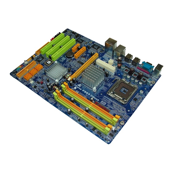
Page 7: Motherboard Layout (For Ver 5.X )
TForce P965 OT HERBOARD AYOUT JCFA N1 JK BM S 1 LGA775 J PRNT1 CPU1 Intel JRJ45US B 1 P965 JATX PWR1 JA UDIO 1 JATX PWR2 Super Intel PEX4 _1 ICH8 BAT1 JCMOS 1 P E X1 _1 JS F A N1 PCI1 S A TA 1 BIO S... -
Page 8: Motherboard Layout (For Ver 6.X )
Motherboard Manual OT HERBOARD AYOUT JCFA N1 JK BM S 1 LGA775 J PRNT1 CPU1 Intel JRJ45US B 1 P965 JATX PWR1 JA UDIO 1 JATX PWR2 Super Intel P E X4 _1 ICH8 BAT1 JCMOS 1 P E X1 _1 JS F A N1 PCI1 S A TA 1... -
Page 9: Chapter 2: Hardware Installation
TForce P965 CHAPTER 2: HARDWARE INSTALLATION (CPU) NST ALLING ENT RAL ROCESSING Special Notice: Remove Pin Cap before installation, and make good preservation for future use. When the CPU is removed, cover the Pin Cap on the empty socket to ensure pin legs won’t be damaged. Pin Cap Step 1: Pull the socket locking lever out from the socket and then raise the lever up to a 90-degree angle. - Page 10 Motherboard Manual Step 2: Look for the triangular cut edge on socket, and the golden dot on CPU should point forwards this triangular cut edge. The CPU will fit only in the correct orientation. Step 2-1: Step 2-2: Step 3: Hold the CPU down firmly, and then lower the lever to locked position to complete the installation.
-
Page 11: Fan Headers
TForce P965 FAN H EADERS These fan headers support cooling-fans built in the computer. The fan cable and connector may be different according to the fan manufacturer. Connect the fan cable to the connector while matching the black wire to pin#1. -
Page 12: Installing System Memory
Motherboard Manual NST ALLING YST EM EMORY A. Memory Modules Unlock a DIMM slot by pressing the retaining clips outward. Align a DIMM on the slot such that the notch on the DIMM matches the break on the Slot. Insert the DIMM vertically and firmly into the slot until the retaining chip snap back in place and the DIMM is properly seated. - Page 13 TForce P965 B. Dual Channel Memory installation To trigger the Dual Channel f unction of the motherboard, the memory module must meet the following requirements: Install memory module of the same density in pairs, shown in the f ollowing table. Dual Channel Status DDR2_A1 DDR2_A2 DDR2_B1 DDR2_B2 Enabled Enabled...
-
Page 14: Connectors And Slots
Motherboard Manual ONNECT ORS AND LOT S FDD1: Floppy Disk Conne ctor The motherboard prov ides a standard floppy disk connector that supports 360K, 720K, 1.2M, 1.44M and 2.88M floppy disk ty pes. This connector supports the prov ided f loppy drive ribbon cables. IDE1: Hard Disk Conne ctor The motherboard has a 32-bit Enhanced PCI IDE Controller that prov ides PIO Mode 0~4, Bus Master, and Ultra DMA 33/66/100/133 f unctionality. - Page 15 TForce P965 PEX16_1: PCI-Express x16 Slot PCI-Express 1.0a compliant. Maximum theoretical realized bandwidth of 4GB/s simultaneously per direction, f or an aggregate of 8GB/s totally. PEX4_1: PCI-Expre ss x4 Slot PCI-Express 1.0a compliant. Maximum theoretical realized bandwidth of 1GB/s simultaneously per direction, f or an aggregate of 2GB/s totally.
-
Page 16: Chapter 3: Headers & Jumpers Setup
Motherboard Manual CHAPTER 3: HEADERS & JUMPERS SETUP OW T O ET UP UMPERS The illustration shows how to set up jumpers. When the jumper cap is placed on pins, the jumper is “close”, if not, that means the jumper is “open”. - Page 17 TForce P965 JATXPWR2: ATX Powe r Source Conne ctor JATXPWR2 allows user to connect 24-pin power connector on the ATX power supply. Assignment Assignment +3.3V +3.3V -12V +3.3V Ground Ground PS_ON Ground Ground Ground Ground Ground PW_OK Standby Voltage+5V +12V +12V Ground +3.3V...
- Page 18 Motherboard Manual JUSB3/JUSB4: Heade rs for USB 2.0 Ports at Front Panel This header allows user to connect additional USB cable on the PC f ront panel, and also can be connected with internal USB devices, like USB card reader. Assignment +5V (fused) +5V (fused)
- Page 19 TForce P965 JCMO S1: Cle ar CMOS Heade r By placing the jumper on pin2-3, it allows user to restore the BIOS saf e setting and the CMOS data, please carefully f ollow the procedures to avoid damaging the motherboard. Pin 1-2 Close: Normal Operation (default).
- Page 20 Motherboard Manual JSPDIF_O UT1: Digital Audio-out Conne ctor This connector allows user to connect the PCI bracket SPDIF output header. Assignment SPDIF_OUT Ground JSPDIF_IN1: Digital Audio-in Conne ctor (Optional) This connector allows user to connect the PCI bracket SPDIF input header. Assignment SPDIF_IN Ground...
- Page 21 TForce P965 On-Board LED Indicators There are 2 LED indicators on the motherboard to show system status. LED2 LED1 LED1 and LED2: These 2 LED indicate system power on diagnostics. Please ref er to the table below for different messages: LED1 LED2 Message...
- Page 22 Motherboard Manual JPRNT1: Printe r Port Connector This header allows you to connector printer on the PC. Assignment Assignment -Strobe Ground -ALF Data 6 Data 0 Ground -Error Data 7 Data 1 Ground -Init -ACK Data 2 Ground -Scltin Bus y Data 3 Ground Ground...
-
Page 23: Chapter 4: Overclock Quick Guide
CHAPTER 4: OVERCLOCK QUICK GUIDE OWER NT RODUCT ION Biostar T-Power is a whole new utility that is designed for overclock users. Based on many precise tests, Biostar Engineering Team (BET) has developed this ultimate overclock engine to raise system performance. -
Page 24: T-Power Bios Feature
Motherboard Manual BIOS F OWER EAT URE A. Overclocking Navigator Engine (O.N.E.): ONE provides two powerful overclocking engines: MOS and AOS for both Elite and Casual overclockers. Manual O ve rclock System (M.O .S.) MOS is designed f or experienced overclock users. It allows users to customize personal overclock settings. - Page 25 TForce P965 CPU Ov erclock Setting: CPU Voltage: This f unction will increase CPU stability when overclocking. Howev er, the CPU temperature will increase when CPU voltage is increased. Choices: The range is from 1.2V to 1.725V , with an interv al of 0.0.25V. CPU Frequency: CPU Frequency is directly in proportion to system perf ormance.
- Page 26 Motherboard Manual Automatic O ve rclock System (A.O.S.) For beginners in overclock f ield, BET had developed an easy, fast, and powerf ul feature to increase the system performance, named A.O.S. Based on many tests and experiments, A.O.S. prov ides 3 ideal overclock conf igurations that are able to raise the system perf ormance in a single step.
- Page 27 TForce P965 V12 Tech Engine: This setting will raise about 25%~30% of whole system perf ormance. B. CMOS Reloading Program (C.R.P.): It allows users to sav e different CMOS settings into BIOS-ROM. Users are able to reload any sav ed CMOS setting for customizing system conf igurations.
- Page 28 Motherboard Manual C. Memory Integration Test (M.I.T.): This f unction is under “Ov erclocking Nav igator Engine” item. MIT allows users to test memory compatibilities, and no extra devices or software are needed. Step 1: The def ault setting under this item is “Disabled”; the condition parameter should be changed to “Enable”...
- Page 29 E. Integrated Flash Program (I.F.P.): IFP is a saf e and quick way to upgrade BIOS. Step 1: Go to Biostar website (http://www.biostar.com.tw) to download the latest BIOS f ile. Then, sav e the f ile into a floppy disk. Step 2: Insert the f loppy disk and reboot the system to get into CMOS screen.
- Page 30 Motherboard Manual F. Smart Fan Function: Smart Fan Function is under “PC Health Status”. This is a brilliant f eature to control CPU Temperature vs. Fan speed. When enabling Smart Fan f unction, Fan speed is controlled automatically by CPU temperature. This f unction will protect CPU f rom overheat problem and maintain the system temperature at a saf e lev el.
- Page 31 TForce P965 Start PWM Value When CPU temperature arrives to the set value, the CPU fan will work under Smart Fan Function mode. The range is from 0~127, with an interv al of 1. Slope PWM Choices: 1 PWM Value/℃ (default), 2 PWM Value/℃ , 4 PWM Value/℃ , 8 PWM Value/℃...
-
Page 32: T-Power Windows Feature
Motherboard Manual OWER INDOWS EAT URE A.Hardware Monitor: T-Power Hardware monitor allows users to monitor system voltage, temperature and fan speed accordingly. Additionally, a rescue action will be taken by the program automatically while the system faces an abnormal condition. The program will trigger an alarm or shut down the system when unpredictable errors occur. - Page 33 TForce P965 CPU Te mpe rature This column configures the CPU temperature. There is a wav ef orm to represent the status of CPU temperature. By adjusting , users can easily configure the upper limit of CPU temperature f or system operating. In this diagram, the white line represents the upper limit which user-set f or CPU temperature and the green line shows present CPU temperature.
- Page 34 Motherboard Manual CPU/Batte ry Voltage VCore This item displays the CPU voltage, represented by a light blue line. Users can set the upper and lower limit by adjusting to monitor the CPU operating voltage. If CPU v oltage is higher or lower than the set value, the status line will change into a red warning line, and a warning sound will alert y ou.
- Page 35 Graphic 1 will appear when activ ating this utility. Graphic 1 Clicking on “Biostar” will lead y ou to the Biostar Homepage. This column shows the CPU speed inf ormation.
- Page 36 Motherboard Manual CPU Ov erclocking Settings: By adjusting can configure three items for CPU overclocking. CPU Frequency Range: 200MHz~450MHz. Inter val: 1MHz. CPU Ratio Range: 4~ 25. Inter val: 1. CPU Voltage Range: 0.8V~ 2.0V. Inter val: 0.0125V. Memory Overclocking Settings: By adjusting can configure two items for Memory overclocking.
- Page 37 TForce P965 PCI Overclocking Setting: This diagram shows present PCI working status and helps to monitor PCI peripherals working status. This item cannot be adjusted.
- Page 38 Motherboard Manual C. Smart Fan Function When Smart Fan Function is activated, screens will pop-up to illustrate the fan speed information. CPU Temperature: Show current CPU temperature. CPU Fan speed: Show current CPU Fan speed. iii. System Fan speed: Show current system Fan speed. iv.
- Page 39 TForce P965 Auto: If the gr een indicator is lit up, the Smar t Fan Function is “O n” (Default Setting). Click on this button agai n to c lose Smar t Fan Function, and a scr een as below would pop-up. Ther e will be pulling-meter besides the CPU Fan and System Fan, the CPU Fan and the System Fan speed can be adjusted by adjusting the C ur sor Up or Down.
- Page 40 When Live Update program is activated, a screen will pop up to illustrate BIOS related information. Link to Internet: Click on this button wi ll link to Biostar website and BIOS file will be downloaded. Update BIOS: Click on this button to r un BIOS flashi ng pr ocess, and it’s easy and safe.
-
Page 41: Chapter 5: Useful Help
TForce P965 CHAPTER 5: USEFUL HELP RIVER NST ALLAT ION OT E After you installed your operating system, please insert the Fully Setup Driver CD into your optical drive and install the driver for better system performance. You will see the following window after you insert the CD The setup guide will auto detect your motherboard and operating system. -
Page 42: Award Bios Beep Code
BIOS contents are corrupted. In this Case, please follow the procedure below to restore the BIOS: 1. Make a bootable floppy disk. 2. Download the Flash Utility “AWDFLASH.exe” from the Biostar website: www.biostar.com.tw 3. Confirm motherboard model and download the respectively BIOS from Biostar website. - Page 43 TForce P965 B. CPU Overheated If the system shutdown automatically after power on system for seconds, that means the CPU protection function has been activated. When the CPU is over heated, the motherboard will shutdown automatically to avoid a damage of the CPU, and the system may not power on again.
-
Page 44: Troubleshooting
Motherboard Manual ROUBLESHOOT ING Probable Solution No power to the system at all Make sure power cable is Power light don’t illuminate, f an securely plugged in. inside power supply does not turn Replace cable. Contact technical support. Indicator light on key board does not turn on. - Page 45 TForce P965 This page is intentionally left blank...
-
Page 46: Appendencies: Spec In Other Language
Motherboard Manual APPENDENCIES: SPEC IN OTHER LANGUAGE ERMAN Ver 5.x Ver 6.x LGA 775 LGA 775 Intel Core2Duo / Core2 Quad / Pentiu m 4 / Intel Core2Duo / Core2 Quad / Pentiu m 4 / Pentium D / Celeron D Prozessoren mit bis zu Pentium D / Celeron D Prozessoren mit bis zu 3,8 GHz 3,8 GHz... - Page 47 220 mm (B) X 305 mm (L) Windows 2000 / XP / VISTA Windows 2000 / XP / VISTA Biostar beh ält sich das Rech t vor, ohne Biostar beh ält sich das Rech t vor, ohne OS-Un terstüt Ankündigung die Un terstützung für ein Ankündigung die Un terstützung für ein...
-
Page 48: France
Motherboard Manual RANCE Ver 5.x Ver 6.x LGA 775 LGA 775 Processeu rs In tel Core2Duo / Core2 Quad / Processeu rs In tel Core2Duo / Core2 Quad / Pentium 4 / Pentium D / Celeron D jusqu 'à 3 ,8 Pentium 4 / Pentium D / Celeron D jusqu 'à... - Page 49 Windows 2000 / XP / VISTA Windows 2000 / XP / VISTA Support SE Biostar se réserve le droit d'ajouter ou de Biostar se réserve le droit d'ajouter ou de supprimer le support de SE avec ou sans préavis. supprimer le support de SE avec ou sans préavis.
-
Page 50: Italian
Motherboard Manual T ALIAN Ver 5.x Ver 6.x LGA 775 LGA 775 Processore Intel Core 2Duo / Core 2Quad / Processore Intel Core 2Duo / Core 2Quad / Pentium 4 / Pentium D / Celero n D fi no a 3.8 Pentium 4 / Pentium D / Celero n D fi no a 3.8 Supporto di Hyper -Threadi ng / Execute Supporto di Hyper -Threadi ng / Execute... - Page 51 Windows 2000 / XP / VISTA Windows 2000 / XP / VISTA Sistemi Biostar si riserva il diritto di aggiungere o Biostar si riserva il diritto di aggiungere o operativi rimuovere il supporto di qualsiasi sistema rimuovere il supporto di qualsiasi sistema supportati operativo se nza pre avviso.
-
Page 52: Spanish
Motherboard Manual PANISH Ver 5.x Ver 6.x LGA 775 LGA 775 Procesador Intel Core2Duo / Core2 Quad / Procesador Intel Core2Duo / Core2 Quad / Pentium 4 / Pen tiu m D / Celeron D hasta 3 ,8 GHz Pentium 4 / Pen tiu m D / Celeron D hasta 3 ,8 GHz Admite Hyper-Threading / Bit de deshabilitación Admite Hyper-Threading / Bit de deshabilitación de ejecu ción / In tel SpeedStep®... - Page 53 Windows 2000 / XP / VISTA Windows 2000 / XP / VISTA sistema Biostar se reserva el derecho de añ adir o retirar Biostar se reserva el derecho de añ adir o retirar operativo el soporte de cualqu ier SO con o sin aviso previo.
-
Page 54: Portuguese
Motherboard Manual ORT UGUESE Ver 5.x Ver 6.x LGA 775 LGA 775 Processador In tel Core2Duo / Core2 Quad / Processador In tel Core2Duo / Core2 Quad / Pentium 4 / Pentium D / Celeron D até 3 ,8 GHz Pentium 4 / Pentium D / Celeron D até... - Page 55 Windows 2000 / XP / VISTA Windows 2000 / XP / VISTA Sistemas A Biostar reserva-se o direito de adicionar ou A Biostar reserva-se o direito de adicionar ou operativos remover suporte para qu alquer sistema remover suporte para qu alquer sistema suportados operativo com ou sem aviso prévio.
-
Page 56: Polish
Motherboard Manual OLISH Ver 5.x Ver 6.x LGA 775 LGA 775 Procesor In tel Core2Duo / Core2 Quad / Procesor In tel Core2Duo / Core2 Quad / Pentium 4 / Pentium D / Celeron D do 3,8 GHz Pentium 4 / Pentium D / Celeron D do 3,8 GHz Procesor Obsługa Hyper-Th reading / Execu te Disable Bit / Obsługa Hyper-Th reading / Execu te Disable Bit /... - Page 57 220 mm (S) X 305 mm (W) płyty Obsluga Windows 2000 / XP / VISTA Windows 2000 / XP / VISTA systemu Biostar zastrzega sobie prawo dodawania lub Biostar zastrzega sobie prawo dodawania lub operacyjne odwoływania obsługi dowoln ego systemu odwoływania obsługi dowoln ego systemu...
-
Page 58: Russian
Motherboard Manual RUSSIAN Ver 5.x Ver 6.x LGA 775 LGA 775 Процессор In tel Core2Duo / Core2 Quad / Процессор In tel Core2Duo / Core2 Quad / Pentium 4 / Pentium D / Celeron D до 3.8 ГГц Pentium 4 / Pentium D / Celeron D до 3.8 ГГц (центральн... - Page 59 Windows 2000 / XP / VISTA Windows 2000 / XP / VISTA Поддержка Biostar сохран яет за собой право добавлять Biostar сохран яет за собой право добавлять или удалять средства обеспечения для OS с или удалять средства обеспечения для OS с...
-
Page 60: Arabic
Motherboard Manual ARABIC Ver 6.x Ver 5.x LGA 775 LGA 775 ﻡﻌ ﺎ ﻟﺠﺎتIntel Core2Duo / Core2 Quad / Pentium 4 / ﻡﻌ ﺎ ﻟﺠﺎتIntel Core2Duo / Core2 Quad / Pentium 4 / Pentium D / Celeron D 3 .8 Pentium D / Celeron D 3 .8 ﺝﻴﺠﺎ... - Page 61 Windows 2000 / XP / VISTA Windows 2000 / XP / VISTA ﺕﺤﺘﻔﻆBiostar ﺑﺤﻘﻬﺎ ﻓﻲ إﺿﺎﻓﺔ أو إز ا ﻟﺔ اﻟﺪﻋﻢ ﻷ ي ﻥﻈﺎم ﺕﺸﻐﻴﻞ ﺑﺈﺥﻄﺎ ر أو ﺕﺤﺘﻔﻆBiostar ﺑﺤﻘﻬﺎ ﻓﻲ إﺿﺎﻓﺔ أو إز ا ﻟﺔ اﻟﺪﻋﻢ ﻷ ي ﻥﻈﺎم ﺕﺸﻐﻴﻞ ﺑﺈﺥﻄﺎ ر أو...
-
Page 62: Japanese
Motherboard Manual JAPANESE Ver 5.x Ver 6.x LGA 775 LGA 775 Intel Core2Duo / Core2Qu ad / Pen tiu m 4 / Intel Core2Duo / Core2Qu ad / Pen tiu m 4 / Pentium D / Celeron D processor up to 3 .8 GHz Pentium D / Celeron D processor up to 3 .8 GHz Hyper-Threading / E xecute Disable Bit / Hyper-Threading / E xecute Disable Bit /... - Page 63 シリアルポート LANポート LANポート USBポート USBポート オーディオジャック オーディオジャック ボードサイズ 220 mm (幅) X 305 mm (高さ) 220 mm (幅) X 305 mm (高さ) Windows 2000 / XP / VISTA Windows 2000 / XP / VISTA OSサポート Biostarは事前のサポートなしにOSサポートを追加ま Biostarは事前のサポートなしにOSサポートを追加ま たは削除する権利を留保します。 たは削除する権利を留保します。 2006/11/21...
- Page 64 TForce P965 BIOS Setup BIOS Setup ....................1 1 Main Menu....................3 2 Standard CMOS Features..............7 3 Advanced BIOS Features ...............9 4 Advanced Chipset Features..............16 5 Integrated Peripherals................18 6 Power Management Setup..............23 7 PnP/PCI Configurations...............29 8 PC Health Status ...................32 9 Over Clock Navigator................35 10 CMOS Reload Program (C.R.P.) ............41...
-
Page 65: Bios Setup
TForce P965 BIOS Setup Introduction The purpose of this manual is to describe the settings in the Award™ BIOS Setup program on this motherboard. The Setup program allows users to modify the basic system configuration and save these settings to CMOS RAM. The power of CMOS RAM is supplied by a battery so that it retains the Setup inform ation when the power is turned off. - Page 66 TForce P965 PCI Bus Support This AWARD BIOS also supports Version 2.1 of the Intel PCI (Peripheral Component Interconnect) local bus specification. DRAM Support DDR SDRAM (Double Data Rate Synchronous DRAM) is supported. Supported CPUs This AWARD BIOS supports the Intel CPU. Using Setup Use the arrow keys to highlight items in most of the place, press <Enter>...
-
Page 67: Main Menu
TForce P965 1 Main Menu Once you enter Award BIOS™ CMOS Setup Utility, the Main Menu will appear on the screen. The Main Menu allows you to select from several setup functions. Use the arrow keys to select among the items and press <Enter> to accept and enter the sub-menu. - Page 68 TForce P965 Advanced Chipset Features This submenu allows you to configure special chipset featu res. Integrated Peripherals This submenu allows you to configure cert ain IDE hard drive options and Programmed Input/ Output features. Power Management Setup This submenu allows you to configure the power managem ent features. PnP/PCI Configurations This submenu allows you to configure cert ain “...
- Page 69 TForce P965 Set Supervisor Password Setting the supervisor password will prohibit everyone except the supervisor from making changes using the CMOS Setup Utility. You will be prompted with to enter a password. Set User Password If the Supervisor Password is not set, then the User Password will function in the same way as the Supervisor Password.
- Page 70 TForce P965 Integrate Flashing Program This submenu allows you to upgrade bios.
-
Page 71: Standard Cmos Features
TForce P965 2 Standard CMOS Features The items in Standard CMOS Setup Menu are divided into several categori es. Each category includes no, one or more than one setup items. Use the arrow keys to highlight the item and then use the<PgUp> or <PgDn> keys to select the value you want in each item. - Page 72 TForce P965 Item Options Description 720K, 3.5 in 1.44M, 3.5 in 2.88M, 3.5 in None All Errors Select the situation in which No Errors y ou want the BIOS to stop Halt On All, but Key board the POST process and All, but Diskette notify y ou.
-
Page 73: Advanced Bios Features
TForce P965 3 Advanced BIOS Features Figure 3: Advanced BIOS Setup Cache Setup CPU L3 Cache Depending on the CPU/chipset in use, you may be able to increase memory access time with this option. Enabled (default) Enable cache. Disabled Disable cache. - Page 74 TForce P965 Boot Seq & Floppy Setup This item allows you to setup boot sequence & Floppy. Hard Disk Boot Priority The BIOS will attempt to arrange the Hard Disk boot sequence automatically. You can change the Hard Disk booting sequence here. The Choices: Pri.
- Page 75 TForce P965 First/Second/Third Boot Dev ice The BIOS will attempt to load the operating system in this order. The Choices: Floppy, LS120, Hard Disk, CDROM, ZIP 100, USB-FDD, USB-ZIP , USB-CDROM, LAN, Disabled. Boot Other Dev ice When enabled, BIOS will try to load the operating system fro m other device when it failed to load from the three devices above.
- Page 76 TForce P965 CPU Thermal Control This item can enable or disable the CPU Thermal function. The Choices: Enabled (default), Disabled. Delay Prior to Thermal Set this item to enable the CP U Thermal function to engage after the specified time. The Choices: 4 Min, 8 Min, 16Min (default), 32 Min.
- Page 77 TForce P965 Virus Warning This option allows you to choose the VIRUS Warning feature th at is used to protect the IDE Hard Disk boot sector. If this function is enabled and an attempt is made to write to the boot sector, BIOS will display a warning message on the screen and sound an alarm beep.
- Page 78 TForce P965 Typematic Rate (Chars/Sec) Sets the rate at which a keystroke is repeated when you hold the key down. The Choices: 6 (default), 8, 10, 12, 15, 20, 24, 30. Typematic Dela y (Msec) Sets the delay time after the key is held down before it begins to repeat the keystroke.
- Page 79 TForce P965 Full Screen LOGO Show This item allows you to enable/disable Full Screen LOGO Show. The Choices: Enabled (default), Disabled. Small Logo(EPA) Show This item allows you to select whether the “ Small Logo” shows. The Choices: Disabled (default), Enabled. Summary Screen Show This item allows you to enable/disable the summary screen.
-
Page 80: Advanced Chipset Features
TForce P965 4 Advanced Chipset Features This submenu allows you to configure the speci fic features o f the chipset installed on your system. This chipset manage bus speeds and access to system memory resources, such as DRAM. It also coordinates communications with the PCI bus. - Page 81 TForce P965 PCI Express Root Port Func PCI Express Port 1/ 2 / 3/ 4/ 5/ 6 This item allows you to select the P CI Express P ort. The Choices: Auto (default), Enabled, Disabled. PCI-E Compliancy Mode This item allows you to select the P CI-E Compliancy Mode. The Choices: v1.0a (default), v1.0.
-
Page 82: Integrated Peripherals
TForce P965 5 Integrated Peripherals Figure 5. Integrated Peripherals OnChip IDE Device Highlight the “Press Enter” label next to the “ OnChip IDE Device” l abel and press enter key will take you a submenu with the following options:... - Page 83 TForce P965 IDE HDD Block Mode Block mode is also called block transfer, multiple commands, or multiple sectors read / write. If your IDE hard drive supports block mode (most new drives do), select Enabled for automatic detection of the optimal number of block mode (most new drives do), select Enabled for automatic detection of the optimal number of block read / write per sector where the drive can support.
- Page 84 TForce P965 Onboard Device Highlight the “Press Enter” label next to the “Onboard Device” label and press the enter key will take you a submenu with the following options: USB Controller Select enabled if your system contains a Universal Serial Bus (USB) controller and you use USB peripherals.
- Page 85 TForce P965 Onboard Azalia Audio This item allows you to enable or disable to support Onboard Azalia Audio function. The Choices: Auto (default), Disabled. Onboard PATA IDE<VT6410> The Choices: Enabled (default), Disabled Onboard LAN This item allows you to enable or disable the Onboard LAN. The Choices: Enabled (default), Disabled.
- Page 86 TForce P965 Onboard Serial Port 1 Select an address and corresponding interrupt for the first and second serial ports. The Choices: 3F8/IRQ4 (default), Disabled, 2F8/IRQ3, 3E8/IRQ4, 2E8/IRQ3, Auto. Onboard Parallel Port This item allows you to determine access onboard parallel port controller with which I/O Address.
-
Page 87: Power Management Setup
TForce P965 6 Power Management Setup The Power Management Setup Menu allows you to con figure you r system to utilize energy conservation and power up/power down featu res. Figure 6. Power Management Setup ACPI & Wake Up Events... - Page 88 TForce P965 ACPI Function This item displays the status of the Advanced Configuration and P ower Management (ACP I). The Choices: Enabled (default), Disabled. ACPI Suspend Type The item allows you to select the suspend type under the ACP I operating system.
- Page 89 TForce P965 Time (hh:mm:ss) Alarm You can choose the system boot up time, input hour, minute and second to specify. Note: If you have change the setting, you must let the system boot into operating system, before this function will work. POWER ON Function This item allows you to choose the power on method.
- Page 90 TForce P965 Primary/Secondary IDE 0/1 You can enable or disable P rimary or Secondary RAID 0 or RAID 1 function under this item. The Choices: Disabled (default), Enabled. FDD, COM, LPT Port You can enable or disable FDD, COM, and LP T port under this item. The Choices: Disabled (default), Enabled.
- Page 91 TForce P965 Video Off Method This option determines the manner when the monitor goes blank. V/H SYNC+Blank This selection will cause the system to turn off the vertical and horizontal synchronization ports and write blanks to the video buffer. Blank Screen This option only writes blanks to the video buffer.
- Page 92 TForce P965 Soft-Off by PWR-BTN This item determines the behavior of system power button. Instant off turn o ff the power immediately, and Delay 4 Sec. will require you to press and hold the power button for 4 seconds to cut off the system power. The Choices: Delay 4 Sec, Instant-Off (default).
-
Page 93: Pnp/Pci Configurations
TForce P965 7 PnP/PCI Configurations This section describes configu ring the PCI bus system. PCI, or Personal Computer Interconnect, is a system which allows I/O devices to operate at speeds nearing the speed of the CPU itself uses when communicating with its own special components. - Page 94 TForce P965 The above settings will be shown on the screen only if “ Manual” is chosen for the resources controlled by function. Legacy is the term, which signifies that a resource is assigned to the ISA Bus and provides non-PnP ISA add-on cards. PCI / ISA PnP signify that a resource is assigned to the PCI Bus or provides for ISA PnP add-on cards and peripherals.
- Page 95 TForce P965 Assign IRQ For USB This item allows the users to choose which IRQ to assign for the USB. The Choices: Enabled (default), Disabled. Maximum Payload Size Set the maximum payload size for Transaction packets (TLP). The Choice: 4096 (default.), 128, 256, 512, 1024, 2048.
-
Page 96: Pc Health Status
TForce P965 8 PC Health Status Figure 8: PC Health Status CPU FAN Control Choose “ smart” to reduce the noise caused by CPU FAN. The Choices: Smart (default), Always On. CPU Fan Off<℃> If the CPU Temperature is lower than the set value, FAN will turn off. The Choices: Min=0 Max=127 Key in a DEC number. - Page 97 TForce P965 CPU Fan Full speed <℃> When CPU temperature is reach the set value, the CPU fan will work under Full Speed. The Choices: Min=0 Max=127 Key in a DEC number. Start PWM Value When CPU temperature arrives to the set value, the CPU fan will work under Smart Fan Function mode.
- Page 98 TForce P965 Current CPU Temp This field displays the current temperature o f CPU. Current CPU FAN Speed This field displays the current speed o f CPU fan. Current SYS FAN Speed This field displays the current speed o f SYSTEM fan. Current JNFAN1 Speed This field displays the current speed o f JNFAN1 (North bridge) fan.
-
Page 99: Over Clock Navigator
9 Over Clock Navigator OverClock Navigator OverClock .Navigator is designed for beginners in overclock field. Based on many test and experiments from Biostar Engineer Team, OverClock Navigator provides 3 default overclock con figurations that are able to raise the system performance... - Page 100 TForce P965 Auto OverClock System The Overclock Navigator provides 3 different engines helping you to overclock your system. These engines will boost your system perfo rmance to different level. The Choices: V6 Tech Engine This setting will raise about 5%~10% of whole system perfo rmance. V8 Tech Engine This setting will raise about 15%~25% of whole system perfo rmance.
- Page 101 TForce P965 Manual Overclock System (M.O.S.) MOS is designed for experienced overclock users. It allows users to customize personal overclock setting. Note: Based on our test results; the overclock function achieved the best performance on AMD 3000+ CP U CPU Voltage This item allows you to select CPU Voltage Control.
- Page 102 TForce P965 System Memory Frequency The Choices: Auto (default), 533MHz, 667MHz, 800MHz. CPU Clock Ratio The Choices: 8X(default). Min=8 Max=50 Key in a DEC number. CPU Clock The Choices: 100MHz(default). Min=100 Max=333 Key in a DEC number. PCIE Clock select The Choices: Auto (default), Upto CPU, Fixed 100, Manual PCIE Clock Display the PCIE Clock frequency;...
- Page 103 TForce P965 CAS Latency Time The Choices: Auto (Default), 3, 4, 5, 6. DRAM RAS# to CAS# Delay The Choices: Auto (Default), 3, 4, 5, 6, 7. DRAM RAS# Precharge The Choices: Auto (Default), 3, 4, 5, 6, 7. Precharge delay <tRAS> The Choices: Auto (Default), 9, 10, 11, 12, 13, 14, 15, 16, 17, 18, 19, 20, 21, 22, 23.
- Page 104 TForce P965 Step 2: When the process is done, change the setting back from “ Enabled” to “ Disabled” to complete the test.
-
Page 105: Cmos Reload Program (C.r.p.)
TForce P965 10 CMOS Reload Program (C.R.P.) The CMOS Reload Program (CRP) allows you to save different CMOS settings into BIOS-ROM. You may reload any saved CMOS setting to change system configurations. Moreover, you may save your ideal overclock setting for easier overclocking.
Need help?
Do you have a question about the TForce P965 Ver 5.x and is the answer not in the manual?
Questions and answers