Table of Contents
Advertisement
Quick Links
TForce 6100 AM
Setup Manual
2
FCC Information and Copyright
This equipment has been tested and found to comply with the limits of a Class
B digital device, pursuant to Part 15 of the FCC Rules. These limits are designed
to provide reasonable protection against harmful interference in a residential
installation. This equipment generates, uses and can radiate radio frequency
energy and, if not installed and used in accordance with the instructions, may
cause harmful interference to radio communications. There is no guarantee
that interference will not occur in a particular installation.
The vendor makes no representations or warranties with respect to the
contents here and specially disclaims any implied warranties of merchantability
or fitness for any purpose. Further the vendor reserves the right to revise this
publication and to make changes to the contents here without obligation to
notify any party beforehand.
Duplication of this publication, in part or in whole, is not allowed without first
obtaining the vendor's approval in writing.
The content of this user's manual is subject to be changed without notice and
we will not be responsible for any mistakes found in this user's manual. All the
brand and product names are trademarks of their respective companies.
Advertisement
Chapters
Table of Contents

Related Manuals for Biostar TFORCE 6100 AM2


Summary of Contents for Biostar TFORCE 6100 AM2
- Page 1 TForce 6100 AM Setup Manual FCC Information and Copyright This equipment has been tested and found to comply with the limits of a Class B digital device, pursuant to Part 15 of the FCC Rules. These limits are designed to provide reasonable protection against harmful interference in a residential installation.
-
Page 2: Table Of Contents
Table of Contents Chapter 1: Introduction ........1 Before You Start ................1 Package Checklist ................1 Motherboard Features..............2 Rear Panel Connectors ..............3 Motherboard Layout................. 4 Chapter 2: Hardware Installation ......5 Installing Central Processing Unit (CPU)........5 FAN Headers.................. -
Page 3: Chapter 1: Introduction
TForce 6100 AM2 CHAPTER 1: INTRODUCTION EFORE TART Thank you for choosing our product. Before you start installing the motherboard, please make sure you follow the instructions below: Prepare a dry and stable working environment with sufficient lighting. Always disconnect the computer from power outlet before operation. -
Page 4: Motherboard Features
Motherboard Manual OTHERBOARD EATURES SPEC Socket AM2 AMD 64 Architecture enables 32 and 64 bit computing AMD Athlon 64 / Athlon 64 FX / Sempron Supports Hyper Transport and Cool=n=Quiet processors Support HyperTransport Supports up to 1000 MHz Bandwidth Chipset GeForce 6100 nForce 410 Graphics... -
Page 5: Rear Panel Connectors
Special Features RAID 0 / 1 support Supports Raid 0 and Raid 1 through SATA connector . Biostar Reserves the right to add or remove support for OS Support Windows 2K / XP any OS With or without notice. ANEL... -
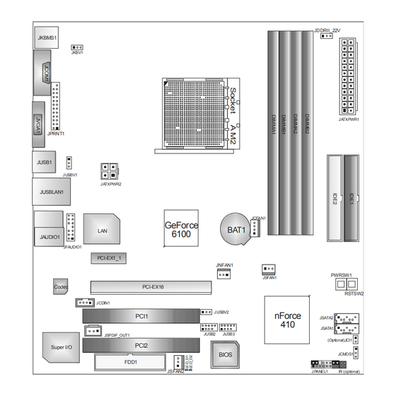
Page 6: Motherboard Layout
Motherboard Manual OTHERBOARD AYOUT JDDRII_22V JKBMS1 JKBV1 JA TXPWR1 JPRNT1 JUSB1 JUSBV1 JA TXPWR2 JUSBLAN1 JCFAN1 GeForce BAT1 6100 JAUDIO1 JFAUDIO1 PCI-EX1_1 JNFAN1 PWRSW1 JSFAN1 Codec PCI-EX16 RSTSW2 JCDIN1 JUSBV2 nForce PCI1 JSATA2 JSATA1 JUSB2 JUSB3 JSPDIF_OUT1 (Optional)JCI1 PCI2 Super I/O BIOS JCMOS1 FDD1... -
Page 7: Chapter 2: Hardware Installation
TForce 6100 AM2 CHAPTER 2: HARDWARE INSTALLATION (CPU) NSTALLING ENTRAL ROCESSING Step 1: Remove the socket protection cap. Step 2: Pull the lever toward direction A from the socket and then raise the lever up to a 90-degree angle. Step 3: Look for the white triangle on socket, and the gold triangle on CPU should point forwards this white triangle. -
Page 8: Fan Headers
Motherboard Manual Step 4: Hold the CPU down firmly, and then close the lever toward direct B to complete the installation. Step 5: Put the CPU Fan on the CPU and buckle it. Connect the CPU FAN power cable to the JCFAN1. This completes the installation. FAN H EADERS These fan headers support cooling-fans built in the computer. - Page 9 TForce 6100 AM2 JSFAN1 /JSFAN2: System Fan Header JSFAN1 Assignment Ground JSFAN1 Smart Fan Control FAN RPM rate sense JSFAN2 Assignment Ground +12V Ground JSFAN2 JNFAN1: North Bridge Fan Header Assignment Ground +12V FAN RPM rate sense JNFAN1 Note: The JCFAN1 Supports 4-pin head connector, and JSFAN1/JSFAN2andJNFAN1 support 3-pin head connector.
-
Page 10: Installing System Memory
Motherboard Manual NSTALLING YSTEM EMORY Unlock a DIMM slot by pressing the retaining clips outward. Align a DIMM on the slot such that the notch on the DIMM matches the break on the Slot. Insert the DIMM vertically and firmly into the slot until the retaining chip snap back in place and the DIMM is properly seated. - Page 11 TForce 6100 AM2 C. Dual Channel Memory installation To trigger the Dual Channel function of the motherboard, the memory module must meet the following requirements: Install memory module of the same density in pairs, shown in the following table. Duual Channel Status DIMMA1...
-
Page 12: Connectors And Slots
Motherboard Manual ONNECTORS AND LOTS FDD1: Floppy Disk Connector The motherboard provides a standard floppy disk connector that supports 360K, 720K, 1.2M, 1.44M and 2.88M floppy disk types. This connector supports the provided floppy drive ribbon cables. IDE1/IDE2: Hard Disk Connectors The motherboard has a 32-bit Enhanced PCI IDE Controller that provides PIO Mode 0~4, Bus Master, and Ultra DMA 33/66/100/133 functionality. - Page 13 TForce 6100 AM2 PCI-Ex16: PCI-Express x16 Slot PCI-Express 1.0a compliant. Maximum theoretical realized bandwidth of 4GB/s simultaneously per direction, for an aggregate of 8GB/s totally. PCI-Ex1_1 PCI-Express 1.0a compliant. Data transfer bandwidth up to 250MB/s per direction; 500MB/s in total.
-
Page 14: Chapter 3: Headers & Jumpers Setup
Motherboard Manual CHAPTER 3: HEADERS & JUMPERS SETUP OW TO ETUP UMPERS The illustration shows how to set up jumpers. When the jumper cap is placed on pins, the jumper is “close”, if not, that means the jumper is “open”. Pin opened Pin closed Pin1-2 closed... - Page 15 TForce 6100 AM2 JIR1: IrDA Connector The motherboard has a Infrared header that supports infrared signal transmitting and receiving device. Assignment IRT X Ground IRRX IR(opt ional) ATX Power Source Connector: JATXPWR1 JATXPWR1 allows user to connect 24-pin power connector on the ATX power supply.
- Page 16 Motherboard Manual JATXPWR2: ATX Power Source Connector By connecting this connector, it will provide +12V to CPU power circuit. Assignment +12V +12V Ground Ground JUSB2/JUSB3: Headers for USB 2.0 Ports at Front Panel This header allows user to connect additional USB cable on the PC front panel, and also can be connected with internal USB devices, like USB card reader.
- Page 17 TForce 6100 AM2 JUSBV1/JUSBV2: Power Source Headers for USB Ports Pin 1-2 Close: JUSBV1: +5V for USB ports at JUSBLAN1. JUSBV2: +5V for USB ports at front panel (JUSB2/JUSB3). Pin 2-3 Close: JUSBV1: USB ports at JUSBLAN1 are powered by +5V standby voltage.
-
Page 18: Front Panel Audio Header
Motherboard Manual JFAUDIO1: Front Panel Audio Header This header allows user to connect the front audio output cable with the PC front panel. It will disable the output on back panel audio connectors. Assignment Mic in/center Ground Mic power/Bass Audio power Right line out/ Speaker out Right Right line out/... -
Page 19: Clear Cmos Procedures
TForce 6100 AM2 JCMOS1: Clear CMOS Header By placing the jumper on pin2-3, it allows user to restore the BIOS safe setting and the CMOS data, please carefully follow the procedures to avoid damaging the motherboard. Pin 1-2 Close: Normal Operation (default). - Page 20 Motherboard Manual JSATA1~JSATA2: Serial ATA Connectors The motherboard has a PCI to SATA Controller with 2 channels SATA interface, it satisfies the SATA 2.0 spec and with transfer rate of 3.0Gb/s. Assignment Ground J SATA2 Ground J SATA1 Ground JSPDIF_OUT1: Digital Audio-out Connector This connector allows user to connect the PCI bracket SPDIF output header.
- Page 21 TForce 6100 AM2 Power Source Selection Headers for Keyboard/Mouse: JKBMSV1 Pin 1-2 Close: JKBMSV1: +5V for PS/2 keyboard and mouse。 Pin 2-3 Close: JKBMSV1: PS/2 keyboard and mouse are powered with +5V standby voltage. Pin 1-2 close Pin 2-3 close Header to adjust Memory Voltage: JDDR_II>2.2V...
- Page 22 Motherboard Manual On-Board LED Indicators There are 2 LED indicators on the motherboard to show system status. LED_D1 LED_D2 LED_D1 and LED_D2: These 2 LED indicate system power on diagnostics. Please refer to the table below for different messages: LED_D1 LED_D2 Message Normal...
- Page 23 TForce 6100 AM2 JPRNT1: Printer Port Connector This header allows you to connector printer on the PC. Assignment Assignment -Strobe Ground -ALF Data 6 Data 0 Ground -Error Data 7 Data 1 Ground -Init -ACK Data 2 Ground -Scltin Busy...
-
Page 24: Chapter 4: Nvidia Raid Functions
Motherboard Manual CHAPTER 4: NVIDIA RAID FUNCTIONS PERATION YSTEM Supports Windows XP Home/Professional Edition, and Windows 2000 Professional. RRAYS NVRAID supports the following types of RAID arrays: RAID 0: RAID 0 defines a disk striping scheme that improves disk read and write times for many applications. -
Page 25: Chapter 5: Overclock Quick Guide
TForce 6100 AM2 RAID 1: Every read and write is actually carried out in parallel across 2 disk drives in a RAID 1 array system. The mirrored (backup) copy of the data can reside on the same disk or on a second redundant drive in the array. -
Page 26: T-Power Introduction
5.1: OWER NTRODUCTION Biostar T-Power is a whole new utility that is designed for overclock users. Based on many precise tests, Biostar Engineering Team (BET) has developed this ultimate overclock engine to raise system performance. No matter whether under BIOS or Windows interface, T-Power is able to present the best system state according to users’... -
Page 27: T-Power Bios Feature
TForce 6100 AM2 5.2: T-P BIOS F OWER EATURE A. Overclocking Navigator Engine (O.N.E.): ONE provides two powerful overclocking engines: MOS and AOS for both Elite and Casual overclockers. Manual Overclock System (M.O.S.) MOS is designed for experienced overclock users. - Page 28 Motherboard Manual CPU Overclock Setting: CPU Voltage: This function will increase CPU stability when overclocking. However, the CPU temperature will increase when CPU voltage is increased. Choices: The range is from 1.2V to 1.725V, with an interval of 0.0.25V. CPU Frequency: CPU Frequency is directly in proportion to system performance.
- Page 29 TForce 6100 AM2 Automatic Overclock System (A.O.S.) For beginners in overclock field, BET had developed an easy, fast, and powerful feature to increase the system performance, named A.O.S. Based on many tests and experiments, A.O.S. provides 3 ideal overclock configurations that are able to raise the system performance in a single step.
- Page 30 Motherboard Manual V12 Tech Engine: This setting will raise about 25%~30% of whole system performance. Notices: Not all types of AMD CPU perform above overclock setting ideally; the difference will be based on the selected CPU model. From BET experiments, the Atholon64 FX CPU is not suitable for this A.O.S. feature. B.
- Page 31 TForce 6100 AM2 C. Memory Integration Test (M.I.T.): This function is under “Overclocking Navigator Engine” item. MIT allows users to test memory compatibilities, and no extra devices or software are needed. Step 1: The default setting under this item is “Disabled”; the condition parameter should be changed to “Enable”...
- Page 32 E. Integrated Flash Program (I.F.P.): IFP is a safe and quick way to upgrade BIOS. Step 1: Go to Biostar website (http://www.biostar.com.tw) to download the latest BIOS file. Then, save the file into a floppy disk. Step 2: Insert the floppy disk and reboot the system to get into CMOS screen.
- Page 33 TForce 6100 AM2 F. Smart Fan Function: Smart Fan Function is under “PC Health Status”. This is a brilliant feature to control CPU Temperature vs. Fan speed. When enabling Smart Fan function, Fan speed is controlled automatically by CPU temperature.
- Page 34 Motherboard Manual Start PWM Value When CPU temperature arrives to the set value, the CPU fan will work under Smart Fan Function mode. The range is from 0~127, with an interval of 1. Choices: 32 (default). Slope PWM Choices: 1 PWM Value/℃ (default), 2 PWM Value/℃, 4 PWM Value/℃, 8 PWM Value/℃, 16 PWM Value/℃, 32 PWM Value/℃, 64PWM Value/℃.
-
Page 35: T-Power Windows Feature
TForce 6100 AM2 OWER INDOWS EATURE A.Hardware Monitor: T-Power Hardware monitor allows users to monitor system voltage, temperature and fan speed accordingly. Additionally, a rescue action will be taken by the program automatically while the system faces an abnormal condition. The program will trigger an alarm or shut down the system when unpredictable errors occur. -
Page 36: Cpu Temperature
Motherboard Manual CPU Temperature This column configures the CPU temperature. There is a waveform to represent the status of CPU temperature. By adjusting , users can easily configure the upper limit of CPU temperature for system operating. In this diagram, the white line represents the upper limit which user-set for CPU temperature and the green line shows present CPU temperature. - Page 37 TForce 6100 AM2 CPU/Battery Voltage VCore This item displays the CPU voltage, represented by a light blue line. Users can set the upper and lower limit by adjusting to monitor the CPU operating voltage. If CPU voltage is higher or lower than the set value, the status line will change into a red warning line, and a warning sound will alert you.
- Page 38 Graphic 1 will appear when activating this utility. Graphic 1 Clicking on “Biostar” will lead you to the Biostar Homepage. This column shows the CPU speed information. C. Click on this button and the utility will pop-up 4 sub-screens (Please refers to Graphic 3).
- Page 39 TForce 6100 AM2 CPU Overclocking Settings: By adjusting can configure three items for CPU overclocking. CPU Frequency Range: 200MHz~450MHz. Interval: 1MHz. CPU Ratio Range: 4~25. Interval: 1. CPU Voltage Range: 0.8V~2.0V. Interval: 0.0125V. Memory Overclocking Settings: By adjusting can configure two items for Memory overclocking.
- Page 40 Motherboard Manual PCI Overclocking Setting: This diagram shows present PCI working status and helps to monitor PCI peripherals working status. This item cannot be adjusted.
- Page 41 TForce 6100 AM2 C. Smart Fan Function When Smart Fan Function is activated, screens will pop-up to illustrate the fan speed information. CPU Temperature: Show current CPU temperature. CPU Fan speed: Show current CPU Fan speed. iii. System Fan speed: Show current system Fan speed.
- Page 42 Motherboard Manual Auto: If the green indicator is lit up, the Smart Fan Function is “On” (Default Setting). Click on this button again to close Smart Fan Function, and a screen as below would pop-up. There will be pulling-meter besides the CPU Fan and System Fan, the CPU Fan and the System Fan speed can be adjusted by adjusting the Cursor Up or Down.
- Page 43 When Live Update program is activated, a screen will pop up to illustrate BIOS related information. Link to Internet: Click on this button will link to Biostar website and BIOS file will be downloaded. Update BIOS: Click on this button to run BIOS flashing process, and it’s easy and safe.
-
Page 44: Chapter 6: Useful Help
Motherboard Manual CHAPTER 6: USEFUL HELP RIVER NSTALLATION After you installed your operating system, please insert the Fully Setup Driver CD into your optical drive and install the driver for better system performance. You will see the following window after you insert the CD The setup guide will auto detect your motherboard and operating system. -
Page 45: Award Bios Beep Code
BIOS contents are corrupted. In this Case, please follow the procedure below to restore the BIOS: 1. Make a bootable floppy disk. 2. Download the Flash Utility “AWDFLASH.exe” from the Biostar website: www.biostar.com.tw 3. Confirm motherboard model and download the respectively BIOS from Biostar website. - Page 46 Motherboard Manual B. CPU Overheated If the system shutdown automatically after power on system for seconds, that means the CPU protection function has been activated. When the CPU is over heated, the motherboard will shutdown automatically to avoid a damage of the CPU, and the system may not power on again.
-
Page 47: Troubleshooting
TForce 6100 AM2 6.4 T ROUBLESHOOTING Probable Solution No power to the system at all Make sure power cable is Power light don’t illuminate, fan securely plugged in. inside power supply does not turn Replace cable. Contact technical support. Indicator light on keyboard does not turn on. -
Page 48: Appendencies: Spec In Other Language
Motherboard Manual APPENDENCIES: SPEC IN OTHER LANGUAGE ERMAN Spezifikationen Sockel AM2 Die AMD 64-Architektur unterstützt eine 32-Bit- und 64-Bit-Datenverarbeitung AMD Athlon 64 / Athlon 64 FX / Sempron Unterstützt Hyper Transport und Cool’n’Quiet Prozessoren Unterstützt HyperTransport mit einer Bandbreite von bis zu 1000 MHz GeForce 6100 nForce 410 Chipsatz... - Page 49 244 mm (B) X 244 mm (L) NVIDIA nTunes Sonderfunkti onen Unterstützt RAID 0 / 1 Biostar behält sich das Recht vor , ohne Ankündigung die OS-Unterstüt Windows 2K / XP Unterstützung für ein Betriebssystem hinzuzufügen zung oder zu entfernen.
-
Page 50: France
Motherboard Manual RANCE SPEC Socket AM2 L'architecture AMD 64 permet le calcul 32 et 64 bits Processeurs AMD Athlon 64 / Athlon 64 FX Prend en charge Hyper Transport et Cool’n’Quiet / Sempron Prend en charge Hyper Transport jusqu'à Bus frontal une bande passante de 1000 MHz GeForce 6100 nForce 410... - Page 51 244 mm (l) X 244 mm (H) de la carte Fonctionnali NVIDIA nTunes tés Prise en charge RAID 0 / 1 spéciales Biostar se réserve le droit d'ajouter ou de supprimer le Support SE Windows 2K / XP support de SE avec ou sans préavis.
-
Page 52: Italian
Motherboard Manual TALIAN SPECIFICA Socket AM2 L’architettura AMD 64 abilita la co mputazione 32 e 64 bit Processori AMD Athlon 64 / Athlon 64 FX / Sempron Supporto di Hyper Transport e Cool’n’Quiet Supporto di HyperTransport fino a 1000 MHz di larghezza di banda GeForce 6100 nForce 410 Chipset... - Page 53 244 mm (larghezza) x 244 mm i scheda (altezza) Caratterist nTunes NVIDIA iche Supporto RAID 0 / 1 speciali Sistemi Biostar si riserva il diritto di aggiungere o operativi Windows 2K / XP rimuovere il supporto di qualsiasi sistema supportati operativo senza preavviso.
-
Page 54: Spanish
Motherboard Manual PANISH Especificación Conector AM2 La arquitectura AMD 64 permite el procesado de 32 y 64 bits Procesadores AMD Athlon 64 / Athlon 64 Soporta las tecnologías Hyper Transport y Cool’n’Quiet FX / Sempron Admite HyperTransport con un ancho de banda de hasta 1000 MHz Conjunto de GeForce 6100... - Page 55 244 mm. (A) X 244 Mm. (H) la placa NVIDIA nTunes Funciones especiales Admite RAID 0 / 1 Soporte de Biostar se reserva el derecho de añadir o retirar el Windows 2K / XP sistema soporte de cualquier SO con o sin aviso previo. operativo...
-
Page 56: Portuguese
Motherboard Manual ORTUGUESE ESPECIFICAÇÕES A arquitectura AMD 64 permite uma computação de 32 Socket AM2 e 64 bits Processadores AMD Athlon 64 / Athlon 64 Suporta as tecnologias Hyper Transport e Cool’n’Quiet FX / Sempron Suporta a tecnologia HyperTransport com uma largura de banda até... - Page 57 Característi nTunes da NVIDIA Suporta as funções RAID 0 / 1 especiais Sistemas A Biostar reserva-se o direito de adicionar ou remover Windows 2K / XP operativos suporte para qualquer sistema operativo com ou sem suportados aviso prévio.
-
Page 58: Polish
Motherboard Manual OLISH SPEC Socket AM2 Architektura AMD 64 umożliwia przetwarzanie 32 i 64 Procesor bitowe AMD Athlon 64 / Athlon 64 FX / Sempron Procesory Obsługa Hyper Transport oraz Cool’n’Quiet Obsługa HyperTransport o szerokości pasma do 1000 MHz GeForce 6100 nForce 410 Chipset Maks. - Page 59 Gniazdo audio Wymiary 244 mm (S) X 244 mm (W) płyty NVIDIA nTunes. Funkcje specjalne Obsługa RAID 0 / 1 Obsluga Biostar zastrzega sobie prawo dodawania lub systemu Windows 2K / XP odwoływania obsługi dowolnego systemu operacyjne operacyjnego bez powiadomienia.
-
Page 60: Russian
Motherboard Manual RUSSIAN СПЕЦ. Гнездо AM2 Архитектура AMD 64 разрешать обработка данных (центральн на 32 и 64 бит Процессоры AMD Athlon 64 / Athlon 64 ый Поддержка Hyper Transport и Cool’n’Quiet FX / Althlon 64X2 процессор) Поддержка HyperTransport с пропускной способностью до 1000 МГц Набор... - Page 61 244 мм (Ш) X 244 мм (В) панели Специальн ые NVIDIA nTunes технически е Поддержка RAID 0 / 1 характерис тики Biostar сохраняет за собой право добавлять или Поддержка Windows 2K / XP удалять средства обеспечения для OS с или без предварительного уведомления.
-
Page 62: Arabic
Motherboard Manual ARABIC اﻟﻤﻮاﺻﻔﺎت ﻡﻘﺒﺲAM2 ﺗﻤﻜﻦ ﺗﻘﻨﻴﺔAMD 64 ﺏﺖ و ﺏﻴﺔ ﺏﺴﺮﻋﺔ إﺝﺮاء اﻟﻌﻤﻠﻴﺎت اﻟﺤﺎﺳﻮ وﺣﺪة اﻟﻤﻌﺎﻟﺠﺔ ﻡﻌﺎﻟﺠﺎتAMD Athlon 64 / Athlon 64 FX / ﺗﺪﻋﻢ ﺗﻘﻨﻴﺔHyper Transport وCool’n’Quiet اﻟﻤﺮآﺰﻳﺔ Sempron ﺗﺪﻋﻢ ﺗﻘﻨﻴﺔHyperTransport 0001 ﺏﺘﺮدد ﻳﺼﻞ إﻟﻰ اﻟﻨﺎﻗﻞ اﻷﻡﺎﻡﻲ اﻟﺠﺎﻥﺒﻲ ﺗﺮدد... -
Page 63: Smart Fan
TForce 6100 AM2 اﻟﻤﻮاﺻﻔﺎت Smart Fan( ﻋﺪد وﺹﻠﺔ ﻡﺮوﺣﺔ وﺣﺪة اﻟﻤﻌﺎﻟﺠﺔ اﻟﻤﺮآﺰﻳﺔ ﻡﻊ وﻇﻴﻔﺔ ﻟﺘﻮﺹﻴﻞ اﻟﻄﺎﻗﺔ ﻟﻤﺮوﺣﺔ وﺣﺪة اﻟﻤﻌﺎﻟﺠﺔ ﻋﺪد وﺹﻠﺔ ﻡﺮوﺣﺔ اﻟﻨﻈﺎم ﻟﺘﻮﺹﻴﻞ اﻟﻄﺎﻗﺔ ﻟﻤﺮوﺣﺔ اﻟﻨﻈﺎم ﻋﺪد ﺘﻴﺎري ) اﺥ وﺹﻠﺔ ﻓﺘﺢ اﻟﻬﻴﻜﻞ ﻟﻠﻜﺸﻒ ﻋﻦ اﺥﺘﺮاق اﻟﻬﻴﻜﻞ ﻋﺪد CMOS وﺹﻠﺔ... -
Page 64: Japanese
Motherboard Manual JAPANESE 仕様 AMD 64アーキテクチャでは、32ビットと64ビット計算が可 Socket AM2 能です AMD Athlon 64 / Athlon 64 FX / Sempron ハイパートランスポートとクールアンドクワイアットをサポ プロセッサ ートします 1000 MHz のバンド幅までハイパートランス ポートをサポートします チップセット GeForce 6100 nForce 410 グラフィック GeForce 6100 チップセットに統合 最大の共有ビデオメモリは128MBです ス DDR2 DIMMスロット x 4 デュアル... - Page 65 TForce 6100 AM2 仕様 SATAコネクタ 各コネクタは1つのSATAデバイスをサポートします フロントパネルコネクタ フロントパネル機能をサポートします フロントオーディオコネクタ フロントパネルオーディオ機能をサポートします CDインコネクタ CDオーディオイン機能をサポートします S/PDIFアウトコネクタ デジタルオーディオアウト機能をサポートします CPUファンヘッダ CPUファン電源装置(スマートファン機能を搭載) システムファンヘッダ システムファン電源装置 シャーシオープンヘッダ(オプション) シャーシ侵入検出機能 CMOSクリアヘッダ 各コネクタは2つのフロントパネルUSBポートをサポートし USBコネクタ ます 電源コネクタ(24ピン) 電源コネクタ(4ピン) PS/2キーボード PS/2マウス シリアルポート 背面パネル VGAポート LANポート USBポート オーディオジャック ボードサイズ 244 mm (幅) X 244 mm (高さ) NVIDIA nTunes 特殊機能...
- Page 66 TForce 6100 AM2 BIOS Setup BIOS Setup ....................1 1 Main Menu....................3 2 Standard CMOS Features ..............7 3Advanced BIOS Features ............... 9 4 Advanced Chipset Features ..............16 5 Integrated Peripherals ................. 19 6 Power Management Setup..............25 7 PnP/PCI Configurations ..............
-
Page 67: Bios Setup
TForce 6100 AM2 BIOS Setup BIOS Setup Introduction The purpose of this manual is to describe the settings in the Award™ BIOS Setup program on this motherboard. The Setup program allows users to modify the basic system configuration and save these settings to CMOS RAM. The power of CMOS RAM is supplied by a battery so that it retains the Setup information when the power is turned off. -
Page 68: Pci Bus Support
TForce 6100 AM2 BIOS Setup PCI Bus Support This AWARD BIOS also supports Version 2.1 of the Intel PCI (Peripheral Component Interconnect) local bus specification. DRAM Support DDR SDRAM (Double Data Rate Synchronous DRAM) is supported. Supported CPUs This AWARD BIOS supports the AMD CPU. -
Page 69: Main Menu
TForce 6100 AM2 BIOS Setup 1 Main Menu Once you enter Award BIOS™ CMOS Setup Utility, the Main Menu will appear on the screen. The Main Menu allows you to select from several setup functions. Use the arrow keys to select among the items and press <Enter> to accept and enter the sub-menu. - Page 70 TForce 6100 AM2 BIOS Setup Standard CMOS Features This submenu contains industry standard configurable options. Advanced BIOS Features This submenu allows you to configure advanced features of the BIOS. Advanced Chipset Features This submenu allows you to configure special chipset features.
-
Page 71: Load Optimized Defaults
TForce 6100 AM2 BIOS Setup Load Optimized Defaults This selection allows you to reload the BIOS when problem occurs during system booting sequence. These configurations are factory settings optimized for this system. A confirmation message will be displayed before defaults are set. - Page 72 TForce 6100 AM2 BIOS Setup Exit Without Saving Abandon all changes made during the current session and exit setup. Confirmation message will be displayed before proceeding. Upgrade BIOS This submenu allows you to upgrade bios.
-
Page 73: Standard Cmos Features
TForce 6100 AM2 BIOS Setup 2 Standard CMOS Features The items in Standard CMOS Setup Menu are divided into several categories. Each category includes no, one or more than one setup items. Use the arrow keys to highlight the item and then use the<PgUp> or <PgDn> keys to select the value you want in each item. - Page 74 TForce 6100 AM2 BIOS Setup Item Options Description Press <Enter> to enter the Options are in its sub IDE Secondary Slave sub menu of detailed menu. options. 360K, 5.25 in 1.2M, 5.25 in Select the type of floppy Drive A 720K, 3.5 in...
-
Page 75: 3Advanced Bios Features
TForce 6100 AM2 BIOS Setup 3Advanced BIOS Features Figure 3: Advanced BIOS Setup Boot Seq & Floppy Setup This item allows you to setup boot sequence & Floppy. - Page 76 TForce 6100 AM2 BIOS Setup Removable Device Priority Select Removable Boot Device Priority. The Choices: Floppy Disks, Zip100, USB-FDD0, USB-FDD1, USB-ZIP0, USB-ZIP1, LS120. Hard Disk Boot Priority The BIOS will attempt to arrange the Hard Disk boot sequence automatically. You can change the Hard Disk booting sequence here.
- Page 77 TForce 6100 AM2 BIOS Setup First/Second/Third Boot Device The BIOS will attempt to load the operating system in this order. The Choices: Floppy, LS120, HDD-0, SCSI, CDROM, HDD-1, HDD-2, HDD-3, ZIP100, LAN, HPT370, Disabled. Boot Other Device When enabled, BIOS will try to load the operating system from other device when it failed to load from the three devices above.
-
Page 78: Cpu Feature
TForce 6100 AM2 BIOS Setup CPU Internal Cache Depending on the CPU/chipset in use, you may be able to increase memory access time with this option. Enabled (default) Enable cache. Disabled Disable cache. External Cache This option enables or disables “Level 2” secondary cache on the CPU, which may improve performance. -
Page 79: Virus Warning
TForce 6100 AM2 BIOS Setup Virus Warning This option allows you to choose the VIRUS Warning feature that is used to protect the IDE Hard Disk boot sector. If this function is enabled and an attempt is made to write to the boot sector, BIOS will display a warning message on the screen and sound an alarm beep. - Page 80 TForce 6100 AM2 BIOS Setup Typematic Delay (Msec) Sets the delay time after the key is held down before it begins to repeat the keystroke. The Choices: 250 (default), 500, 750, 1000. Security Option This option will enable only individuals with passwords to bring the system online and/or to use the CMOS Setup Utility.
- Page 81 TForce 6100 AM2 BIOS Setup Summary Screen Show This item allows you to enable/disable the summary screen. Summary screen means system configuration and PCI device listing. The Choices: Disabled (default), Enabled.
-
Page 82: Advanced Chipset Features
TForce 6100 AM2 BIOS Setup 4 Advanced Chipset Features This submenu allows you to configure the specific features of the chipset installed on your system. This chipset manage bus speeds and access to system memory resources, such as DRAM. It also coordinates communications with the PCI bus. - Page 83 TForce 6100 AM2 BIOS Setup K8<->NB HT Width The Choices: (default), NB<->SB HT Width The Choices: (default), Err94 Enh This item allows you to enable/disable the “sequential Prufetch Feature” of K8 CPU. The Choices: Auto (default), Disabled. Onboard GPU The Choices: Auto (default), Always Enable.
- Page 84 TForce 6100 AM2 BIOS Setup System BIOS Cacheable Selecting the “Disabled ” option allows caching of the system BIOS ROM at F0000h-FFFFFh which can improve system performance. However, any programs writing to this area of memory will cause conflicts and result in system errors.
-
Page 85: Integrated Peripherals
TForce 6100 AM2 BIOS Setup 5 Integrated Peripherals Figure 5. Integrated Peripherals IDE Function Setup Highlight the “Press Enter” label next to the “VIA OnChip IDE Device” label and press enter key will take you a submenu with the following options:... - Page 86 TForce 6100 AM2 BIOS Setup On-chip IDE Channel 0/1 The motherboard chipset contains a PCI IDE interface with support for two IDE channels. Select “Enabled” to activate the first and/or second IDE interface. Select “Disabled” to deactivate an interface if you are going to install a primary and/or secondary add-in IDE interface.
-
Page 87: Raid Config
TForce 6100 AM2 BIOS Setup RAID Config RAID Enable This option allows you to enable or disable RAID function. The Choices: Disabled (default), Enabled. SATA 1/2 Primary/Secondary RAID This option allows you to enable or disable SATA A Primary/Secondary RAID. - Page 88 TForce 6100 AM2 BIOS Setup Power On Function This item allows you to choose the power on method. The Choices: Button Only (default), Password, Hot Key, Mouse Left, Mouse Right, Any Key, Keyboard 98. KB Power on Password Input password and press Enter to set the Keyboard power on password.
-
Page 89: Onchip Usb
TForce 6100 AM2 BIOS Setup OnChip USB This option should be enabled if your system has a USB installed on the system board. You may need to disable this feature if you add a higher performance controller. The Choices: V1.1+V2.0 (default), Disabled, V1.1 USB Memory Type The Choices: Base Memory<640k>(default). -
Page 90: Ide Hdd Block Mode
TForce 6100 AM2 BIOS Setup MAC Media Interface This option allows you to control the onboard MAC Media Interface. The Choices: Pin Strap (default), Disabled IDE HDD Block Mode Block mode is also called block transfer, multiple commands, or multiple sectors read / write. -
Page 91: Power Management Setup
TForce 6100 AM2 BIOS Setup 6 Power Management Setup The Power Management Setup Menu allows you to configure your system to utilize energy conservation and power up/power down features. Figure 6. Power Management Setup ACPI Function This item displays the status of the Advanced Configuration and Power Management (ACPI). -
Page 92: Power Management
TForce 6100 AM2 BIOS Setup Power Management This category allows you to select the power saving method and is directly related to the following modes: 1. HDD Power Down. 2. Suspend Mode. There are three options of Power Management, three of which have fixed mode settings Min. - Page 93 TForce 6100 AM2 BIOS Setup Soft-Off by PWR-BTN This item determines the behavior of system power button. Instant off turn off the power immediately, and Delay 4 Sec. will require you to press and hold the power button for 4 seconds to cut off the system power.
-
Page 94: Pnp/Pci Configurations
TForce 6100 AM2 BIOS Setup 7 PnP/PCI Configurations This section describes configuring the PCI bus system. PCI, or Personal Computer Interconnect, is a system which allows I/O devices to operate at speeds nearing the speed of the CPU itself uses when communicating with its own special components. -
Page 95: Reset Configuration Data
TForce 6100 AM2 BIOS Setup Reset Configuration Data The system BIOS supports the PnP feature which requires the system to record which resources are assigned and protects resources from conflict. Every peripheral device has a node, which is called ESCD. This node records which resources are assigned to it. -
Page 96: Irq Resources
TForce 6100 AM2 BIOS Setup IRQ Resources This submenu will allow you to assign each system interrupt a type, depending on the type of device using the interrupt. When you press the “Press Enter” tag, you will be directed to a submenu that will allow you to configure the system interrupts. -
Page 97: Pc Health Status
TForce 6100 AM2 BIOS Setup 8 PC Health Status Figure 8: PC Health Status Shutdown Temperature This item allows you to set up the CPU shutdown Temperature. This item is only effective under Windows 98 ACPI mode. The Choices: Disabled (default) , 70℃/ 158℉, 75℃/ 167℉, 80℃/ 176℉. - Page 98 TForce 6100 AM2 BIOS Setup Current CPU Temp This field displays the current temperature of CPU. Current CPU FAN Speed This field displays the current speed of CPU fan. Current SYS FAN Speed This field displays the current speed SYSTEM fan.
-
Page 99: Over Clock Navigator Engine
9 Over Clock Navigator Engine OverClock Navigator OverClock .Navigator is designed for beginners in overclock field. Based on many test and experiments from Biostar Engineer Team, OverClock Navigator provides 3 default overclock configurations that are able to raise the system performance... - Page 100 TForce 6100 AM2 BIOS Setup Cautions: Not every AMD CPU performs the above overclock setting ideally; the difference may vary with the installed CPU model. From BET experiment, the Atholon64 FX CPU is not suitable for this A.O.S. feature. Manual Overclock System (M.O.S.) MOS is designed for experienced overclock users.
- Page 101 TForce 6100 AM2 BIOS Setup Memory Voltage The Choices: 1.85V (default).1.90V, 1.95V, 2.00V CPU Frequency This item allows you to select the CPU Frequency. The Choices: 200 to 450 with an interval of 1. (Default value is 200) HT Frequency This item allows you to select the HT Frequency.
- Page 102 TForce 6100 AM2 BIOS Setup DQS Training Control The Choices: Perform DQS (Default), Skip DQS CKE base power down mode The Choices: Enable (Default), Disable. CKE base power down The Choices: per Channel (Default)., Per CS. Memclock tri-stating The Choices: Disable (Default), Enable.
- Page 103 TForce 6100 AM2 BIOS Setup (Trcd) RAS to CAS R/W Delay The Choices: 6 Clocks(Default), 3 Clocks, 4 clocks, 5 clocks.. (Trrd) RAS to RAS Delay The Choices: 5 Clocks(Default), 2 Clocks, 3 clocks, 4 clocks.. (Trp) Row Precharge Time The Choices: 6 Clocks(Default), 3 Clocks, 4clocks, 5clocks..
- Page 104 TForce 6100 AM2 BIOS Setup Step 2: When the process is done, change the setting back from “Enabled” to “Disabled” complete test.
-
Page 105: Cmos Reload Program(C.r.p.)
TForce 6100 AM2 BIOS Setup 10 CMOS Reload Program(C.R.P.) The CMOS Reload Program (CRP) allows you to save different CMOS settings into BIOS-ROM. You may reload any saved CMOS setting to change system configurations. Moreover, you may save your ideal overclock setting for easier overclocking.
Need help?
Do you have a question about the TFORCE 6100 AM2 and is the answer not in the manual?
Questions and answers