Advertisement
Table of Contents
- 1 Features
- 2 Safety Instructions
- 3 Recognize Safety Information
- 4 Understand Signal Words
- 5 General Information
- 6 Choosing Proper Location for the Air Conditioner
- 7 Installation Instructions
- 8 Roof Preparation
- 9 Wiring Requirements
- 10 Installing the Air Conditioner
- 11 Wiring the System
- 12 Field Wiring Diagram
- Download this manual
USA
SERVICE OFFICE
Dometic Corporation
2320 Industrial Parkway
Elkhart, IN 46515
574-294-2511
CANADA
Dometic Distribution
866 Langs Drive
Cambridge, Ontario
CANADA N3H 2N7
519-653-4390
ALL INITIAL INSTALLATIONS MUST BE APPROVED BY THE SALES DEPT.
For Service Center
Assistance Call:
800-544-4881
C
US
INSTALLATION
INSTRUCTIONS
REVISION:
Form No. 3308970.015 2/05
(Replaces 3308970.007)
(French 3308971.013)
©2005 Dometic Corporation
LaGrange, IN 46761
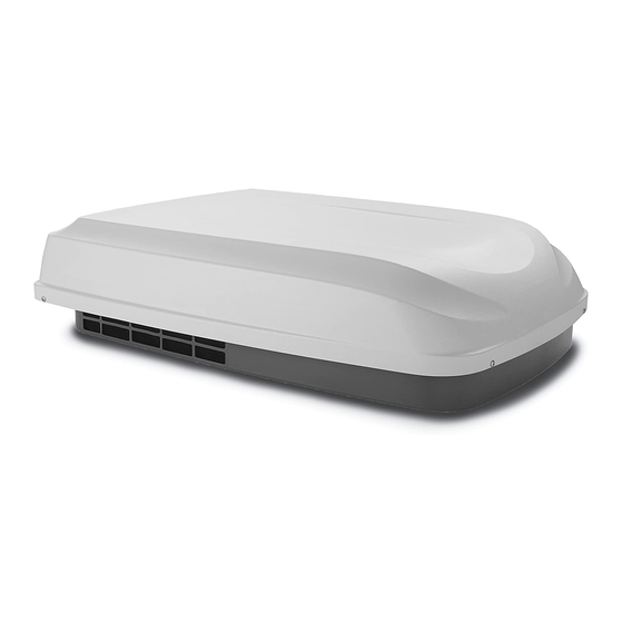
Roof-Top Air Conditioner
used with one of following:
3105935 Quick Cool Return Air Cover
3308120 Genesis Air Filtration System
3106995 Analog Wall Thermostat
THIS UNIT IS DESIGNED FOR OEM INSTALLATION
This manual must be read and un-
derstood before installation, ad-
justment, service, or maintenance
is performed. This unit must be in-
stalled by a qualified service tech-
nician. Modification of this product
can be extremely hazardous and
could result in personal injury or
property damage.
Important:
These Instructions
must stay with unit.
Owner read carefully.
MODEL 6204XX
3105007 Return Air Cover
and
Lire et comprendre ce manuel avant de
procéder à l'installation, à des réglages,
de l'entretien ou des réparations.
L'installation de cet appareil doit être
effectuée par un réparateur qualifié.
Toute modification de cet appareil peut
être extrêmement dangereuse et
entraîner des blessures ou dommages
matériels.
1
RECORD THIS UNIT INFORMATION FOR
FUTURE REFERENCE:
Model Number
Serial Number
Date Purchased
Models
620412.331
620425.336
620415.331
620426.331
620415.336
620426.336
620425.331
Advertisement
Table of Contents

Subscribe to Our Youtube Channel
Related Manuals for Dometic 620412.331


Summary of Contents for Dometic 620412.331
- Page 1 Models INSTALLATION 620412.331 620425.336 620415.331 620426.331 INSTRUCTIONS 620415.336 620426.336 620425.331 REVISION: Form No. 3308970.015 2/05 Important: These Instructions (Replaces 3308970.007) must stay with unit. (French 3308971.013) Owner read carefully. ©2005 Dometic Corporation LaGrange, IN 46761...
-
Page 2: Features
620412, 620415, 620425 & 620426 Series Installation Instructions SAFETY INSTRUCTIONS GENERAL INFORMATION Product features or specifications as described or illustrated This manual has safety information and instruc- are subject to change without notice. tions to help users eliminate or reduce the risk of B. - Page 3 620412, 620415, 620425 & 620426 Series Installation Instructions...
-
Page 4: Choosing Proper Location For The Air Conditioner
1. Read Installation and Operating Instructions care- fully before attempting to start your air conditioner installation. 2. Dometic Corporation will not be liable for any dam- It is preferred that the air conditioner be installed on ages or injury incurred due to failure in following a relatively flat and level roof section measured these instructions. -
Page 5: Roof Preparation
620412, 620415, 620425 & 620426 Series Installation Instructions FIG. 4 4" FIG. 5 4" 7-1/8” REAR 4-1/8” 21-3/8” UNIT Center Line 14-1/4" x 14-1/4” (±1/8”) OPENING of Unit 7-1/8” d. If the opening exceeds 14-3/8" x 14-3/8", it will KEEP THESE AREAS 12"... - Page 6 Return air to the air conditioner must be filtered the ductwork will not collapse or bend during to prevent dirt accumulation on air conditioner and after the installation. Dometic Corporation cooling surface. will not be liable for roof structural or ceiling 5.
- Page 7 Corporation in writing. The following instructions are LOW VOLTAGE WIRES: CCC, CONTROL CABLE(S) or 7-Wire Analog Cable based upon the use of 3105007 Dometic Return Air Kit, 12VDC Furnace Load Shed 3105935 Dometic Return Air Kit or 3308120 Genesis Air...
-
Page 8: Wiring Requirements
620412, 620415, 620425 & 620426 Series Installation Instructions D. Wiring Requirements d. Leave approximately 6" of cable extending through the wall for connection to the thermo- Route a copper 12 AWG, with ground, 120 VAC stat. supply line from the time delay fuse or circuit breaker e. -
Page 9: Installing The Air Conditioner
620412, 620415, 620425 & 620426 Series Installation Instructions F. Placing Air Conditioner On The Roof G. Installing The Air Conditioner Installing Unit with 3105007 or 3105935 Return Air 1. Remove the air conditioner from the carton and dis- card carton. See FIG. 9. Kit. - Page 10 620412, 620415, 620425 & 620426 Series Installation Instructions e. Install the Romex connector in the junction box. c. Place divider plate up to bottom of air condi- Hold the ceiling template up to the 14-1/4" x tioner base pan firmly. The foam tape on the 14-1/4"...
- Page 11 620412, 620415, 620425 & 620426 Series Installation Instructions Installing unit with 3308120 Genesis Air Filtration Do Not Peel Tape Off FIG. 19 Adhesive System Return Air Kit. For unit with 3105007 or Base Pan 3105935 Return Air Kit, see page 9. Upside FIG.
- Page 12 Important: A duct adapter (not supplied) must be installed between the unit discharge and the customer installed cen- CAUTION ter duct. This duct adapter must be approved by Dometic. If bolts are left loose there may not be ad- a. Check gasket alignment of the air conditioner over the roof opening and adjust if necessary.
-
Page 13: Wiring The System
620412, 620415, 620425 & 620426 Series Installation Instructions H. Wiring The System 2. Connection Of 120 Volt Power Supply a. Route power supply line through Romex con- Reach up into the return air opening and pull the re- nector into junction box on side away from the maining wires down. - Page 14 620412, 620415, 620425 & 620426 Series Installation Instructions Operating Manual or Users Guide for a description If solar panel is installed see instructions packaged Note: with solar panel option. of the air conditioner operation. a. Connect the red wire from the unit, the red wire Installing unit with 3308120 Genesis Air Filtra- from the filter indicator light with the red DC positive power lead.
-
Page 15: Field Wiring Diagram
620412, 620415, 620425 & 620426 Series Installation Instructions FIELD WIRING DIAGRAM COMPRESSOR FREEZE CONTROL MOTOR RUN CAP RUN CAP CON 3 CON 3 HERM CON 2 CON 2 LIMIT SWITCH START CAP CON 1 CON 1 MOTOR SPLICE CAP SPLICE CAP STARTER BLU/WHT PASSED...
Need help?
Do you have a question about the 620412.331 and is the answer not in the manual?
Questions and answers