Table of Contents
Advertisement
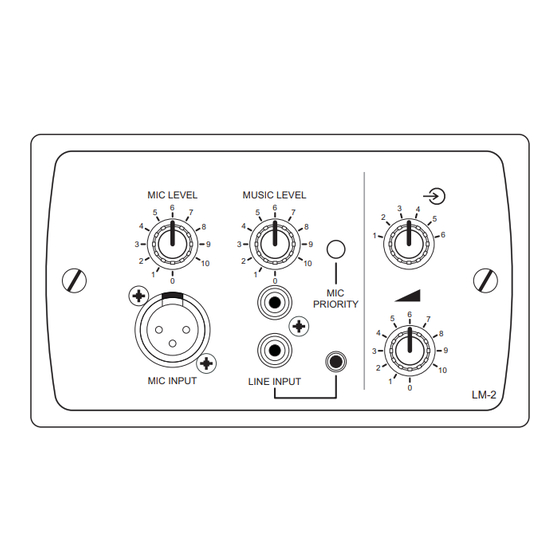
LM-2 Series Remote Mic/Line
Mixer/Control Modules
MIC LEVEL
6
5
7
4
8
3
9
2
10
1
0
MIC INPUT
MUSIC LEVEL
6
3
4
5
7
2
5
4
8
1
6
3
9
2
10
1
0
MIC
PRIORITY
6
5
7
4
8
3
9
2
10
LINE INPUT
1
0
LM-2
MIC LEVEL
MUSIC LEVEL
6
5
7
5
4
8
4
9
3
3
2
2
10
1
1
0
MIC INPUT
LINE INPUT
Installation Guide
MIC LEVEL
MUSIC LEVEL
6
6
5
7
5
7
4
4
8
3
9
3
2
2
10
1
1
0
0
MIC INPUT
LINE INPUT
6
3
4
7
2
5
8
6
1
9
10
0
MIC
PRIORITY
6
5
7
4
8
3
9
2
10
1
0
LM-2A
LM-2 Installation Guide v1.0
3
4
2
5
8
1
6
9
10
MIC
PRIORITY
6
5
7
4
8
3
9
2
10
1
0
LM-2D
1
Advertisement
Table of Contents

Related Manuals for Cloud LM-2 Series


Summary of Contents for Cloud LM-2 Series
- Page 1 LM-2 Series Remote Mic/Line Mixer/Control Modules MIC LEVEL MUSIC LEVEL MIC LEVEL MUSIC LEVEL PRIORITY PRIORITY MIC INPUT LINE INPUT MIC INPUT LINE INPUT LM-2D LM-2 MIC LEVEL MUSIC LEVEL PRIORITY MIC INPUT LINE INPUT LM-2A Installation Guide LM-2 Installation Guide v1.0...
-
Page 2: Table Of Contents
Contents Introduction ............................ 3 Mounting - mechanical ........................3 Faceplate Controls and Connections ................... 4 Block Diagram ..........................5 Installation - connections ......................5 Configuring the Facility Port ............................7 Connecting multiple LM-2s ............................7 Local inputs .................................. 7 Remote controls ................................. 8 LM-2 Priority Operation........................ -
Page 3: Introduction
Mounting - mechanical LM-2 (UK version) The Cloud LM-2 fits a standard UK-style dual-gang electrical back box. The box used should have a depth of at least 35 mm. LM-2A (US version) The Cloud LM-2A fits a standard US dual-gang electrical ‘J’ box in vertical orientation. The box used should have a depth of at least 1¼”. -
Page 4: Faceplate Controls And Connections
Faceplate Controls and Connections MIC LEVEL MUSIC LEVEL PRIORITY MIC INPUT LINE INPUT LM-2 UK version illustrated MIC INPUT – 3-pin XLR3F connector for dynamic microphones. Note that the LM-2 does not provide phantom power. LINE INPUT (a) – 2 x phono (RCA) sockets for connection of sources such as CD players, audio mixers, radio mic receivers, etc;... -
Page 5: Block Diagram
Block Diagram RJ45 RJ45 Installation - connections The LM-2 has two PCBs mounted on the rear of the faceplate. The OUTPUT RJ45 connector is located on the upper PCB while the LINK RJ45 connector is on the lower: OUTPUT LINK LOCATION OF REAR RJ45 CONNECTORS (‘DIN’... - Page 6 The LM-2’s OUTPUT connector should be connected to the host unit’s FACILITY PORT for the Zone in which it is installed* with screened Cat 5 cable and shielded RJ45 plugs. 100 m max Connect to Connect to OUTPUT socket FACILITY PORT Screened Cat 5 cable OUTPUT...
-
Page 7: Configuring The Facility Port
Configuring the Facility Port The mic and line inputs on the LM-2 module will be available in the Zone as soon as the module is connected to the host unit’s Facility Port for that Zone. The volume of the mic and line inputs will be determined solely by the level controls on the LM-2 faceplate and unaffected by any of the host unit’s front panel controls. -
Page 8: Remote Controls
Note that it is also possible to “daisy-chain” standard Cloud RL-1 and RSL-6 remote control plates to the LINK connector. This would be useful if additional background music control points were required in the Zone, but not additional system inputs. -
Page 9: Lm-2 Priority Operation
LM-2 Priority Operation If the MIC PRIORITY button on the LM-2 faceplate is not pressed, mic and/or line signals connected at the module will be routed to the Zone to whose Facility Port the LM-2 is wired, and heard through the audio system at volumes which can be controlled from the MIC LEVEL and MUSIC LEVEL controls on the faceplate. -
Page 10: Power Considerations
Installation and User Guide where full details of power supply ratings can be found. Should you have any questions concerning the installation and connection of the LM-2, please visit www.cloud.co.uk/resources, where you will find additional technical information. - Page 11 LM-2 Installation Guide v1.0...
- Page 12 Cloud Electronics Limited Cloud Electronics USA 140 Staniforth Road 2065 Sidewinder Drive, Sheffield S9 3HF Suite 200, Park City, England Utah 84060. Tel: +44 (0)114 244 7051 United States of America. Fax: +44 (0)114 242 5462 Toll Free: 0855 810 0161 email: info@cloud.co.uk...
Need help?
Do you have a question about the LM-2 Series and is the answer not in the manual?
Questions and answers