Table of Contents
Advertisement
Quick Links
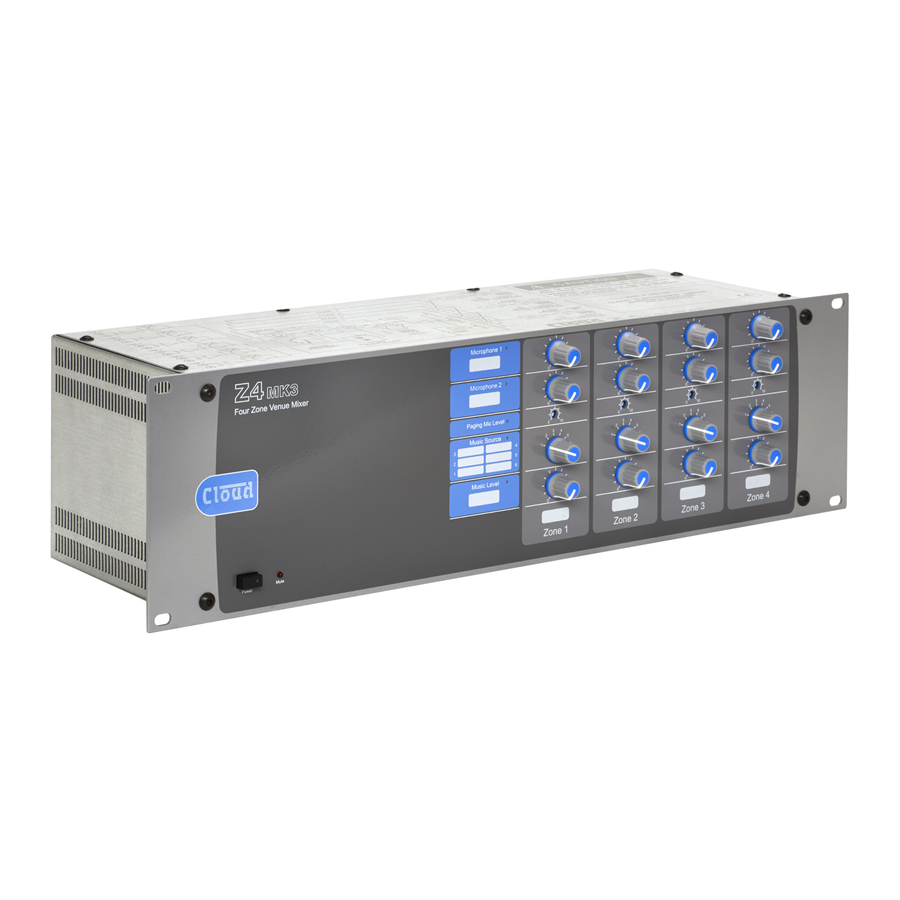
Z4
MK3
ZONE MIXERS
4
MK3
Four Zone Venue Mixer
Mute
Power
8
Microphone 1
MK3
0
10
Eight Zone Venue Mixer
Microphone 2
0
10
Paging Mic Level
0
10
Music Source
3
4
2
5
3
4
1
6
2
5
1
6
Music Level
0
10
Zone 1
Mute
Power
Installation and User Guide
& Z8
MK3
Microphone 1
0
10
0
Microphone 2
0
10
0
Paging Mic Level
0
10
0
Music Source
3
4
2
5
1
6
Music Level
0
10
0
Zone 1
Zone 2
0
10
0
10
0
10
0
0
10
0
10
0
10
0
0
10
0
10
0
10
0
0
10
0
10
0
10
0
Zone 2
Zone 3
Zone 4
Zone 5
10
0
10
0
10
10
0
10
0
10
10
0
10
0
10
10
0
10
0
10
Zone 3
Zone 4
10
0
10
0
10
0
10
10
0
10
0
10
0
10
10
0
10
0
10
0
10
10
0
10
0
10
0
10
Zone 6
Zone 7
Zone 8
Z4-8
Installation and User Guide v1.2
MK3
Advertisement
Table of Contents

Related Manuals for Cloud Z4MK3


Summary of Contents for Cloud Z4MK3
- Page 1 & Z8 ZONE MIXERS Microphone 1 Four Zone Venue Mixer Microphone 2 Paging Mic Level Music Source Music Level Zone 1 Zone 2 Zone 3 Zone 4 Mute Power Microphone 1 Eight Zone Venue Mixer Microphone 2 Paging Mic Level Music Source Music Level Zone 1...
-
Page 2: Table Of Contents
Contents Safety Information ......................... 4 Safety Notes regarding Installation ..........................4 Conformities ................................... 4 Safety Considerations and Information ........................4 Caution – High Voltage .............................. 4 Caution – Mains Fuse ..............................4 Caution – Servicing ..............................4 OVERVIEW ............................. 5 Introduction .................................. - Page 3 SETTING UP & OPERATION ....................15 Music Inputs .................................. 15 Gain & level ................................15 Local/remote control ............................... 15 Microphone Inputs ..............................15 Phantom Power ................................. 15 Gain & level ................................15 EQ ....................................15 High-pass filter ................................15 Paging mic input ................................16 Phantom Power .................................
-
Page 4: Safety Information
The lightning flash with the arrowhead symbol within Safety Information an equilateral triangle, is intended to alert you to the presence of uninsulated dangerous voltages within the Important Safety Instructions product’s enclosure that may be of sufficient magnitude to constitute a risk of electric shock. Read these instructions. -
Page 5: Overview
Introduction It is always a good idea to store all packaging (if practical), in case you ever need to return the unit to your Cloud dealer Thank you for purchasing this Cloud Zone Mixer. We are for any reason. -
Page 6: Optional System Components
They may also be retrofitted to a system at a later time. Separate datasheets are available for each of the individual components; download them at www.cloud.co.uk. LM-2 Mic/line input module with remote MUSIC LEVEL... -
Page 7: Pm Series Paging Microphones
PM Series paging microphones PM1 paging microphone The Cloud PM1 paging microphone is also compatible with the and Z4 . It is a much simpler unit which addresses Cloud PM paging microphones may be connected directly only one zone. See “Connecting a PM1 paging mic” on page... -
Page 8: Description Of Front Panel
Description of front panel Microphone 1 Eight Zone Venue Mixer Microphone 2 Paging Mic Level Music Source Music Level Zone 1 Zone 2 Zone 3 Zone 4 Zone 5 Zone 6 Zone 7 Zone 8 Mute Power Note - The front panel of the Z8 is shown above. -
Page 9: Description Of Rear Panel
Description of rear panel Note - The rear panel of the Z8 is shown above. The Z4 ’s is identical, except that it only has output connections for Zones 1 - 4. LINE INPUTS – 6 pairs of RCA (phono) sockets (Line 1 to Line 6) for connection of music sources. Inputs are stereo, summed internally to mono. -
Page 10: Installation
System Connections INSTALLATION Music Sources Hardware Considerations Connect the system’s various music sources to LINE 1 to The Z4 and Z8 Zone Mixers are built in 3U-high 19” LINE 6. All line inputs offer unbalanced connection for stereo rack mount enclosures. It is recommended that the Zone sources on a pair of standard RCA jacks (phono sockets). -
Page 11: Zone Outputs
Amplifiers with unbalanced inputs: When using single-core cable, join ‘cold’ to screen at the source If audio amplifiers with only unbalanced inputs are being used Unbalanced (e.g. hi-fi amplifiers), the following wiring should be adopted: input s LEFT RIGHT LEFT Z8II/Z4II Balanced output: pin 1 ground pin 2 cold... -
Page 12: Facility Ports
Priority VCA control White + Green + 15 V Blue Paging System connections White + Blue Cloud PM Series paging microphones may be connected -15 V Green directly to the Z4 and Z8 Music level control (0 to 10 V) -
Page 13: Music Control
(Note that SA versions of PM Series microphones cannot be PAGING ACCESS control port, with the pins corresponding powered by the Z4MK3 or Z8MK3, and need an external to all the zones that the PM1 is to address connected to 0 V. -
Page 14: Music Mute
Music Mute Connecting an RL-1 Series remote control plate Wire the remote control plate as shown below. Either single- External muting of music is available at the MUSIC MUTE core screened or twin-and-screen cable may be used; in the connector. National or Local Authority regulations governing case of the latter, ignore one of the cores. -
Page 15: Setting Up & Operation
Microphone Inputs SETTING UP & OPERATION Phantom Power Each microphone input (MIC 1 & MIC 2) has 15 V phantom Music Inputs power available. This will be adequate to power a wide range of condenser microphones. (Some “studio quality” mics may Gain &... -
Page 16: Paging Mic Input
The PAGING MIC input also has 15 V phantom power available. made. The options are selected via internal jumpers, and This will NOT be required if a Cloud paging microphone is should be set to suit the requirements of the installation being used with the mixer, but may be necessary with other when the system is installed. -
Page 17: Line 6 Priority
Microphone priority over input at is active; during normal operation, the Paging Mic will always take priority over MIC 1 or MIC 2 whatever the setting of J8. Facility Port Note also that because this facility is set on a per-zone basis If an LM-2 remote input module is in use in a zone, it is (by moving J8 on each zone sub-board), it would normally be possible to give any microphone connected at the mixer itself... -
Page 18: Options And Additional Information
LM-2 active input modules – general considerations Cloud LM-2 remote input modules are available in three form factors, to fit double-gang UK, American or German DIN- standard electrical back boxes. Back boxes of either the recessed type or surface-mounting type may be used, providing they are at least 35 mm deep. -
Page 19: Rl-1 Series And Rsl-6 Series Remote Control Plates - General Considerations
RL-1 Series and RSL-6 Series remote control plates – general considerations Cloud RL-1 Series and RSL-6 Series remote control plates are available in three form factors, two fit single-gang UK or American electrical back boxes respectively; the third is a 50 x 50 mm “Media” module, suitable for “Euro-module” mounting frames available in most European countries. -
Page 20: Fitting Loudspeaker Eq Cards
Please check the cloud website (www.cloud.co.uk) for makes and models of loudspeakers for which EQ cards are available. To install equalisation modules, first remove the top cover from the Z4 (six screws). -
Page 21: Appendix
• Area 3 has a Cloud PM paging microphone, which would be used to originate voice messages to any of the areas. The paging level to Area 3 (if required) would be adjusted on installation to be at a level that does not cause feedback. -
Page 22: Pcb Jumper Location And Settings
PCB jumper location and settings The Z4 and Z8 have various internal jumpers, the setting of which may require alteration during installation. Note that there are jumpers on both the motherboard and the individual zone sub-cards. The table below lists each jumper and its purpose, together with the factory default setting. - Page 23 FRONT OF UNIT ZONE SUB-CARDS MOTHERBOARD (at bottom of chassis) POWER TRANSFORMER * Z8 ONLY KEY: Jumper with two possible positions; black square indicates factory default setting. Motherboard jumper locations REMOTE SOURCE + LEVEL RJ45 FACILITY PORT ZONE OUTPUT (COMPONENT SIDE) SOCKET FOR OPTIONAL EQ CARD KEY:...
-
Page 24: Psu Capability And Optional Device Current Consumption
(a club or microphone mixer for example) it would be perfectly normal to expect this to be earthed; we suggest that a transformer be used to isolate the signal and prevent a noisy loop (see page 10). EMC considerations The Cloud Z4 & Z8 fully conform to the relevant electromagnetic compatibility (EMC) standards and are technically well behaved;... -
Page 25: Technical Specifications
Technical Specifications & Z8 Line Inputs: Frequency Response 20 Hz – 20 kHz ±0.5 dB Distortion <0.05% 20 Hz - 20 kHz Sensitivity 195 mV (-12 dBu) to 2.0V (+8 dBu) Input Gain Control 20 dB range Input Impedance 47 kohms Headroom >20 dB Noise... - Page 26 Z4-8 Installation and User Guide v1.2...
- Page 27 Z4-8 Installation and User Guide v1.2...
- Page 28 Z4-8 Installation and User Guide v1.2...
- Page 29 Z4-8 Installation and User Guide v1.2...
- Page 30 Z4-8 Installation and User Guide v1.2...
- Page 31 Z4-8 Installation and User Guide v1.2...
- Page 32 Cloud Electronics Limited Cloud Electronics USA 140 Staniforth Road 2065 Sidewinder Drive, Sheffield S9 3HF Suite 200, Park City, England Utah 84060. Tel: +44 (0)114 244 7051 United States of America. Fax: +44 (0)114 242 5462 Toll Free: 0855 810 0161 email: info@cloud.co.uk...
Need help?
Do you have a question about the Z4MK3 and is the answer not in the manual?
Questions and answers