ESI -50L Hardware Installation Manual
Communications server
Hide thumbs
Also See for ESI-50L:
- Administrator's manual (40 pages) ,
- User manual (88 pages) ,
- Administrator's manual (39 pages)
Table of Contents
Advertisement
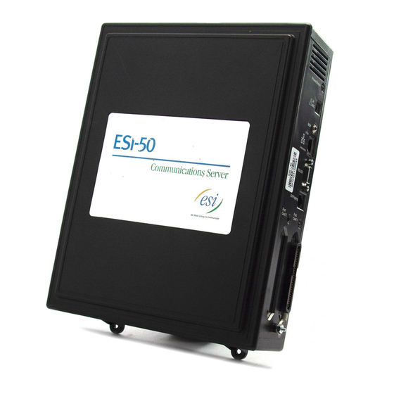
ESI-50L Communications Server
Hardware Installation Manual
0450-1159
Rev. C
Copyright © 2008 ESI (Estech Systems, Inc.).
IVX is a registered trademark of Estech Systems, Inc. Ethernet is a registered trademark of
Xerox Corporation. Motorola and ColdFire are registered trademarks of Motorola, Inc. Rayovac is a
registered trademark of Rayovac Corporation. Act! is a registered trademark of Symantec
Corporation. Goldmine is a trademark of Goldmine Software Corporation. Microsoft, Windows, NT
and Outlook are registered trademarks of Microsoft Corporation. Panasonic and DBS are registered
trademarks of Matsushita Electric Corporation of America. Smart Jack is a trademark of Westell
Technologies, Inc. Information contained herein is subject to change without notice. Certain features
described herein may not be available at initial release. ESI products are protected by various U.S.
Patents, granted and pending. Visit ESI on the Web at www.esi-estech.com.
Advertisement
Table of Contents

Subscribe to Our Youtube Channel
Related Manuals for ESI ESI-50L


Summary of Contents for ESI ESI-50L
- Page 1 Technologies, Inc. Information contained herein is subject to change without notice. Certain features described herein may not be available at initial release. ESI products are protected by various U.S. Patents, granted and pending. Visit ESI on the Web at www.esi-estech.com.
-
Page 2: Table Of Contents
Expansion Cabinet installation ..........F.2 Port card installation..............F.3 Memory Module installation or replacement......F.4 LED functions .................F.4 ESI Presence Management installation ........F.4 Important: For information concerning the programming of an ESI-50L Communications Server, see the ESI-50L Programming Manual (ESI document # 0450-1137). -
Page 3: Overview
482 port cards. Memory Modules and port cards are packed separately and are mounted in each system’s cabinet during installation. The external 482 card also is used by the ESI-50L, the ESI C-Plus, and IVX S-Class Generation II systems. -
Page 4: Nsp
Built into the main board, the NSP (Network Services Processor) serves as a bridge between an Ethernet- based network and the ESI-50L. Using TCP/IP, the NSP communicates directly with specific PC applications for maintenance of, and integration with, the ESI-50L. -
Page 5: Phones
ESI Cordless Handsets The ESI-50L also supports ESI’s digital Cordless Handsets. Each comes in two sizes — small and large — and includes four familiar fixed feature keys, four programmable feature keys, and a headset jack. The Base Station for each ESI digital Cordless Handset uses a standard line cord and is line-powered. -
Page 6: Feature Phone Overlays
DESI Lite, which allows you to print on the overlays. For assistance with DESI products, contact DESI (the DESI Web site contains contact information). Tip: Remember that ESI System Programmer, ESI Personal Programmer, and VIP — software titles all available from www.esiresellers.com — also let you print on the overlays as well as perform many other... -
Page 7: Licensing
• The customer (site) name. • The phone number of the CO line or the public IP address of the NSP. • The quantity of VIP Professional licenses. For more information about the NSP, refer to NSP Installation Made Simple (ESI #0450-0669). -
Page 8: System Capacities
The ESI-50 supports only PRI. IVC 12 is built into ESI-50 main board; supports up to 12 local IP or up to eight remote IP channels. Esi-Link channels are allocated to “reserved” ports; i.e. Esi-Link channels do not reduce CO or station capacity. -
Page 9: Translation Tables
Max. RFID tags (“electronic keys”) ESI Cellular Management features ESI-50L ESI-50 Dialing plans (-digits) Three Four Three Support for ESI Cellular Management See the ESI-50L Programming Manual (ESI document #0450-1137) or the ESI Presence Management Installation Manual (ESI document #0450-0792). -
Page 10: Cautions And Regulatory Information
• Do not use liquids or aerosols to clean any system equipment; rather, use a cloth that is only slightly damp. • An ESI Communications Server contains no components that are serviceable by either non-Resellers or non-manufacturer technicians. All service must be referred to the Reseller for further handling. -
Page 11: Regulatory Information
Installation: The device is equipped with a USOC connector. Registration Number: 1T1MF08B33727. Ringer equivalence number (REN): 0.8 Hearing-aid compatibility This equipment, utilizing telephone station equipment manufactured by ESI, meets all FCC requirements for hearing-aid compatibility. -
Page 12: Hardware Installation
ESI-50L Hardware Installation Manual Hardware installation Hardware installation Site location As with most electronic equipment, the environmental considerations for this site need to observe good common sense. Provide a dry, clean, and accessible area. Locate space in the telephone equipment room, which will provide easy connection to the 66 blocks and 110 VAC power. -
Page 13: Opening The Base Cabinet
Expansion Cabinet installation The Expansion Cabinet allows the ESI-50L’s capacity to grow by up to two additional port cards. The cards are connected via ribbon cables, through the opening in the back of the Expansion Cabinet, to the Base Cabinet. -
Page 14: Port Card Installation
Hardware installation Port card installation Adding or replacing port cards will require the system to be taken out of service (the ESI-50L doesn’t support “hot-swapping” of its port cards). Important: The ESI-50L can use only the 482 port card (see “Port card options,” page A.1). -
Page 15: Memory Module Installation Or Replacement
Hardware installation Memory Module installation or replacement Note: The Memory Module has a proprietary formatting scheme — do not attempt to install a non-ESI drive. Contact ESI for a replacement Memory Module, if needed. Adding or replacing the CompactFlash Memory Module will require that the ESI-50L be taken out of service. -
Page 16: External Connections
• Connect the grounding lugs of all units to system ground Note: ESI Communications Server lines are protected against a 10 KV surge only if the earth ground procedures described above are followed. - Page 17 “freeze.” Though it is hard to predict exactly when different ESI systems will have problems with modified sine wave or square waveform UPSs (meaning during a power failure event or the recovery from one), it’s fair to assume that a problem will eventually arise from the use of such UPSs.
-
Page 18: Moh Port
Note: The system will buffer up to 1,000 SMDR records in non-volatile memory when the Maintenance/ SMDR serial port is in use for programming or uploading (such as during use of ESI System Programmer). If the buffer becomes full, the system will discard the oldest records. -
Page 19: External Paging Device Connection
Connect a standard 66 or 110 block to each digital port card by using a male 50-pin amphenol cable to each port card female connector located on the cabinet. The connector closest to the wall is the first card; on other ESI... -
Page 20: Co Line Connection
Each analog port will support only a single analog device. The ESI-50L supports a maximum of eight analog devices. All analog ports provide Type I Caller ID information (Caller ID with call waiting is not supported). -
Page 21: 60-Key Expansion Console Connection
4. If necessary, remove the clear plastic overlay from the keys on the Expansion Console. 5. For the customer’s convenience, label the paper overlay to show how the keys are programmed (we suggest you use ESI System Programmer for this). 6. Install the labeled paper overlay on the 60-Key Expansion Console. -
Page 22: 60-Key Second Expansion Console Connection
7. For the customer’s convenience, label the paper overlay to show how the keys are programmed (we suggest you use the ESI System Programmer PC software application for this). 8. Install the labeled paper overlays on the two 60-Key Expansion Consoles. -
Page 23: Installing Esi's Cordless Handsets
This base station is line-powered and therefore needs no AC power. • Wall-mount(s), a belt clip, and a Quick Reference Guide. Each ESI Cordless Handset is keyed to only one base station and takes up one digital port on a 482 card. Base station installation Due to each site’s unique characteristics, the range and distance information we’ll provide herein is... - Page 24 Layout of building/offices, and locations of base stations. This can be a hand-drawn diagram with locations of base stations (you can fax it to ESI at 972 422-9705; be sure to indicate that it goes to Technical Support). The objective is to give the ESI technician an idea of the site’s layout.
-
Page 25: Port Card Connections
ESI-50L Hardware Installation Manual External connections Port card connections Term Wire color Signal RJ11 Port White-Blue Data+ Green Digital Blue-White Data- White-Orange Data+ Green Digital Orange-White Data- White-Green Data+ Green Digital Green-White Data- White-Brown Data+ Green Digital Brown-White Data- White-Slate... -
Page 26: Cabinet Worksheet
ESI-50L Hardware Installation Manual External connections Cabinet worksheet ESI-50L • Base and Expansion Cabinets Base Cabinet Expansion Cabinet Term. Wire color Signal RJ11 Pt. Crd. 1 Pt. Crd. 2 Pt. Crd. 3 Pt. Crd. 4 [Main board] Card type White-Blue... -
Page 27: Index
Power, G.1 Connecting, G.5 Power supply. See Cautions Console, B.1, G.6, G.7 Transformers, wall-mount, A.1 ESI Cordless Handsets. See Phones Regulatory information (U.S. and Canada), E.2 ESI Presence Management, D.1 Ringer equivalence number (REN), E.2 Expansion Console, B.1, G.6, G.7 Serial ports, G.3...
Need help?
Do you have a question about the ESI-50L and is the answer not in the manual?
Questions and answers