Table of Contents
Advertisement
IP Server 900
Hardware Installation Manual
0450-1305
Rev. E
Copyright © 2013 ESI (Estech Systems, Inc.).
IVX is a registered trademark of Estech Systems, Inc. Ethernet is a registered trademark of
Xerox Corporation. Motorola and ColdFire are registered trademarks of Motorola, Inc. Rayovac is a
registered trademark of Rayovac Corporation. Act! is a registered trademark of Sage Software, Inc.
Goldmine is a trademark of Goldmine Software Corporation. Microsoft, Windows, Word, NT and
Outlook are registered trademarks of Microsoft Corporation. Panasonic and DBS are registered
trademarks of Matsushita Electric Corporation of America. Novell and Netware are registered
trademarks of Novell, Inc. Smart Jack is a trademark of Westell Technologies, Inc. Information
contained herein is subject to change without notice. Certain features described herein may not be
available at initial release. ESI products are protected by various U.S. Patents, granted and pending.
Visit ESI at www.esi-estech.com.
Advertisement
Table of Contents

Subscribe to Our Youtube Channel
Related Manuals for ESI IP Server 900


Summary of Contents for ESI IP Server 900
- Page 1 Novell, Inc. Smart Jack is a trademark of Westell Technologies, Inc. Information contained herein is subject to change without notice. Certain features described herein may not be available at initial release. ESI products are protected by various U.S. Patents, granted and pending. Visit ESI at www.esi-estech.com.
-
Page 2: Table Of Contents
ESI digital phones................ F.2 ESI Cordless Handsets ............... F.3 Expansion Consoles ..............F.4 Phone overlays ................F.4 VIP 7 Softphone................F.4 Important: For information concerning the programming of an IP Server 900, see the IP Server 900 Programming Manual (ESI document # 0450-1307). -
Page 3: Overview
G.729a resource module which provides an optional 48 sessions of the G.729a audio codec for use on SIP COs or ESI-Link channels. In addition, it allows up to four analog or digital (D/A) modules (see “Module options,” page A.2), and connects to an optional expansion carrier card that allows up to four more modules. -
Page 4: Power Supply
CSU that can be connected directly to a network interface unit, SmartJack, or ISDN PRI. All 24 CO ports are allocated (regardless of whether they are assigned or used). UIP — Provides 63 universal IP ports which can be used for any combination of: local or remote ESI IP •... -
Page 5: Cautions And Regulatory Information
• Do not use liquids or aerosols to clean any system equipment; rather, use a cloth that is only slightly damp. • The ESI system contains no components that are serviceable by either non-Resellers or non-manufacturer technicians. All service must be referred to the Reseller for further handling. -
Page 6: Regulatory Information
Installation: The device is equipped with a T568B connector. Registration Number: 1T1MF08B33727. Ringer Equivalence Number (REN): 0.8. Hearing-aid compatibility This equipment, utilizing telephone phone equipment manufactured by ESI, meets all FCC requirements for hearing-aid compatibility. -
Page 7: Précautions Et Informations Réglementaires
• N'utilisez pas de liquides ou d’aérosols pour nettoyer tout l’équipement du système, mais plutôt utiliser un chiffon qui est seulement légèrement humide. • Le système ESI ne contient aucun composant qui sont utilisables soit par non-revendeurs ou de non-fabricant de techniciens. Tous les services doivent être soumis au revendeur pour la manipulation. -
Page 8: Informations Réglementaires
L’installation: L’appareil est équipé d’un connecteur T568B. Numéro d'Enregistrement: 1T1MF08B33727. Numéro d’Équivalence Sonnerie (REN en Anglais): 0.8. Prothèse Auditive Compatibilité Cet équipement, en utilisant l’équipement poste téléphonique fabriqué par ESI, respecte toutes les exigences de la FCC pour la compatibilité des prothèses auditives. -
Page 9: Ordering And Installing Pri Circuits
PRI channel or group of channels, typically referred to as a hunt group. When you create a pilot number in the IP Server 900 you must enter the maximum number of PRI “B” channels (one to 23) that can be used for that pilot number’s hunt group. - Page 10 PRI and CSU or Smart Jack. • Span Type — When the distance from the IP Server 900 to the CSU, SmartJack, or multiplexer (all of which are considered repeaters) is less than 655 feet use the DSX-1 setting. For longer distances use DS-1. This value is used in combination with the Line Build-Out setting below to define loss levels and compensation when programming the PRI circuit in the IP Server 900.
- Page 11 IP Server 900 Hardware Installation Manual Ordering and installing PRI circuits...
-
Page 12: System Capacities
IP Server 900 Hardware Installation Manual System capacities System capacities Important: Each ESI Presence Management RFID Reader (digital model) consumes one digital phone port. Phones and COs The specifications shown below reflect system maximum capacities and configurations. Not all of the phone and CO maximums can be reached simultaneously. - Page 13 The frequency and duration of video recordings from each camera as well as overall network load to the system — such as local or remote IP phones, SIP trunks, SIP stations, and usage of ESI applications (e.g., ESI Mobile Messaging, VIP 7, or ESI Presence Management) —...
-
Page 14: Licensing
For more information about the NSP, refer to NSP Installation Made Simple (ESI #0450-0669). An ESI 60 (IP model), ESI 40 (IP model), 48-Key IP Feature Phone II, IP Cordless Handset (Local or Remote), VIP Softphone, or SIP phone. -
Page 15: Phones
Complies with Layer 3 DiffServ (RFC 2475) Quality of Service (QoS) implementations. Important: Each ESI IP phone draws up to 7.25 watts3 at 48 volts DC; therefore, each advertises itself to a Power over Ethernet switch as a Class 3 device per the 802.3af standard. Most PoE switches adhering to this standard will provide up to 12.5 watts for each Class 3 device. -
Page 16: Esi Digital Phones
Headset jack for 48-Key Feature Phones (Digital, Digital TAPI, Local IP, or Remote IP) manufactured after March, 2004 only. Not all handsets are compatible with your ESI phone; contact your ESI Reseller for a list of compatible models. Noise-cancelling headsets are not... -
Page 17: Esi Cordless Handsets
Phones ESI Cordless Handsets The IP Server 900 also supports ESI’s digital, Local IP, and Remote IP Cordless Handsets (but only the ESI Cordless Handset II models, not the original ESI Cordless Handset). The ESI Cordless Handset II includes seven familiar fixed feature keys, eight programmable feature keys, a speakerphone, and a headset jack. -
Page 18: Expansion Consoles
120 programmable feature keys in addition to its own complement of keys. A fully configured IP Server 900 allows up to 80 phones to have one or two Expansion Consoles (60-Key and 60-Key Second). -
Page 19: Hardware Installation
Restore function later. After removing an IP 900 D/A Carrier Card from the box, install it as follows in the IP Server 900. 1. Loosen the two thumbscrews on either side of the Master Control Unit that secure the base tray to the top, and then slide the bottom tray out and away from the top cover. -
Page 20: Ip Server 900 Module Installation Instructions
Restore function later. After removing an IP Server 900 module from the box, install it as follows: 1. Loosen the two thumbscrews on either side of the Master Control Unit that secure the base tray to the top, and then slide the bottom tray out and away from the top cover. -
Page 21: Ip Server 900 Ip Resource Module Installation Instructions
Whenever you change the module configuration, you must create a backup file for the new configuration to be able to perform the Restore function later. After removing an IP Server 900 IP Resource Module (either the UIP Resource Module or the G.729a Resource Module) from the box, install it in the Master Control Unit as follows. -
Page 22: About Replacing Modules
IP Server 900 Hardware Installation Manual Hardware installation About replacing modules Important: The main board, expansion board, and expansion cable cannot be removed or replaced under power. The entire system must be powered-down when you install, remove, or replace any of these components. -
Page 23: Memory Module Installation Or Replacement
…not lit at all, the T1/PRI circuit is in service but is idle. …lit solidly, the T1/PRI circuit is out of service. ESI Presence Management installation For information on installing ESI Presence Management, see its ESI Presence Management Installation Manual (ESI document # 0450-0792). -
Page 24: External Connections
• Connect the grounding lugs of all units to system ground Note: IP Server 900 lines are protected against a 10 KV surge only if the earth ground procedures described above are followed. - Page 25 “freeze.” Though it is hard to predict exactly when different ESI systems will have problems with modified sine wave or square waveform UPSs (meaning during a power failure event or the recovery from one), it’s fair to assume that a problem will eventually arise from the use of such UPSs.
-
Page 26: Moh Port
• control pair to pins 5 and 6. CO line connection SIP COs The IP Server 900 supports SIP COs via Universal IP (UIP) ports. Partial SIP applications are supported through line programming. Currently supported SIP COs are: Broadvox Cox Cable nTelos •... - Page 27 Line compensation (or line build-out) is provided as necessary between the CSU or Smart Jack and the IP Server 900. The system does not support pulse dialing; all incoming dialing will default to DTMF digits. When working with a PRI line, the DLC (i.e., the DLC, DLC12, or DLC82) supports these switch protocols: National-NI2 (default) •...
-
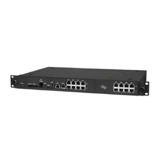
Page 28: Module Connections
IP Server 900 Hardware Installation Manual External Connections Module connections Refer to this graphic for the following module installation details (for more details, see “About replacing modules,” page G.4): 4-FXO and 4-FXS Modules Connector M1–M4 Pins Pins Pins Pins row(s) -
Page 29: 60-Key Expansion Console Connection
External Connections 60-Key Expansion Console connection Notes: The 60-Key Expansion Console can be connected to an ESI 60, ESI 40, or 48-Key Feature Phone. If connecting both a 60-Key Expansion Console and a 60-Key Second Expansion Console to an ESI phone see “60-Key Second Expansion Console connection,”... -
Page 30: 60-Key Second Expansion Console Connection
4. To keep cabling out of the way, thread the expansion “Y” cable into the slots on the bottom of the phone and the two Expansion Consoles. 5. Program the keys on the two Expansion Consoles using the same procedure as with the ESI phone (press PROG/HELP 2). -
Page 31: Installing Esi's Cordless Handsets
Cordless Handset is IP, the base phone uses Power over Ethernet (PoE). • Wall-mount(s), a belt clip, and a Quick Reference Guide. Each ESI Cordless Handset is keyed to only one base phone and takes up one port (digital or IP) on a port card. Base phone installation Due to each site’s unique characteristics, the range and distance information we’ll provide herein is... - Page 32 Repeaters as the user moves from one coverage area to another. When it’s connected to a Repeater, the ESI Cordless Handset II operates exactly as it does when connected to its base phone, and the handoff from the base phone to the Repeater occurs seamlessly without disturbing the end user, even during an active call.
- Page 33 Layout of building/offices, and locations of base phones and repeaters. This can be a hand-drawn diagram with locations of base phones (you can fax it to ESI at 972 422-9705; be sure to indicate that it goes to Technical Support). The objective is to give the ESI technician an idea of the site’s layout.
-
Page 34: Index
IP Server 900 Hardware Installation Manual Index Index 60-Key Expansion Console, F.4, H.4, H.5 Modules 60-Key Second Expansion Console, F.4, H.4, H.5 Capacities, A.2 Battery. See Cautions MOH, H.3 Cautions, B.1 Overlays, F.4 Battery, B.1 Paging, H.3 Fuse, B.1 Phones Power supply, B.1...
Need help?
Do you have a question about the IP Server 900 and is the answer not in the manual?
Questions and answers