Table of Contents
Advertisement
Quick Links
Advertisement
Table of Contents

Related Manuals for Pacific AMX series

Summary of Contents for Pacific AMX series
- Page 3 THE INFORMATION CONTAINED IN THIS MANUAL IS PROPRIETARY TO PACIFIC POWER SOURCE. MAY NOT BE COPIED OR REPRINTED WITHOUT ITS EXPRESSED WRITTEN CONSENT. PACIFIC POWER SOURCE, INC. 17692 FITCH IRVINE, CALIF. 92614 PPS PART NO. 139250 REVISION A October 2003...
-
Page 4: Limited Warranty
LIMITED WARRANTY Pacific Power Source (PPS) warrants each unit to be free from defects in material and workmanship. For the period of two (2) years from the date of shipment to the purchaser, PPS will either repair or replace, at its sole discretion, any unit returned to its factory in Irvine, California. -
Page 5: Table Of Contents
TABLE OF CONTENTS PAGE GENERAL USING THIS MANUAL ........................1 SAFETY NOTICES..........................2 GENERAL PRODUCT DESCRIPTION..................5 SPECIFICATIONS ELECTRICAL SPECIFICATIONS....................7 2.1.1 INPUT POWER REQUIREMENTS ....................7 2.1.2 OUTPUT POWER ..........................14 2.1.3 OUTPUT POWER FACTOR ......................28 2.1.4 OUTPUT FREQUENCY ........................28 2.1.5 OUTPUT DISTORTION ........................28 2.1.6 OUTPUT LOAD REGULATION ....................28 2.1.7 INPUT LINE REGULATION ......................28... - Page 6 TABLE OF CONTENTS PAGE OUTPUT POWER CONNECTION ....................70 3.4.1 SINGLE PHASE OUTPUT ......................70 3.4.2 SPLIT PHASE OUTPUT........................74 3.4.3 THREE PHASE OUTPUT......................78 3.4.4 TRANSFORMER OUTPUTS - SPECIAL CONSIDERATIONS..........79 3.4.5 MODELS 390-AMX and 3120-AMX CHASSIS INTERCONNECTIONS........81 REMOTE INTERFACE .........................82 AUX I/O INSTALLATION......................82 EXTERNAL SENSE CONNECTION....................86 OPERATION FRONT PANEL CONTROLS.......................
- Page 7 TABLE OF CONTENTS PAGE SERVICE SERVICE PROCEDURE ......................105 ROSTER OF SYSTEM LEVEL PART NUMBERS ..............105 SUB-ASSEMBLY AND CHASSIS COMPONENT PART NUMBERS........106 7.3.1 FACTORY PART NUMBERS, MODEL 105-AMX ..............106 7.3.2 FACTORY PART NUMBERS, MODEL 108-AMX ..............107 7.3.3 FACTORY PART NUMBERS, MODEL 112-AMX ..............107 7.3.4 FACTORY PART NUMBERS, MODEL 125-AMX ..............108 7.3.5...
- Page 8 LIST OF ILLUSTRATIONS PAGE FIGURE 1.3 AMX-SERIES POWER SOURCE - FRONT VIEW ............4 FIGURE 2.1.2(A) MODEL 105-AMX OUTPUT DERATING CURVES ............15 FIGURE 2.1.2(B) MODEL 108-AMX OUTPUT DERATING CURVES ............16 FIGURE 2.1.2(C) MODEL 112-AMX OUTPUT DERATING CURVES ............17 FIGURE 2.1.2(D) MODEL 125-AMX OUTPUT DERATING CURVES ............18 FIGURE 2.1.2(E) MODEL 140-AMX OUTPUT DERATING CURVES ............19 FIGURE 2.1.2(E2)
-
Page 9: General
Always read this section before operating the equipment. This is especially true when modifications have been installed, since these can change system operation. If questions arise while reading this manual, the user is encouraged to call the Pacific Power Source. Pacific maintains a toll-free number which is 1-800-854-2433. - Page 12 SECTION 1 GENERAL MODEL 305−AMX w/ UMC−31 Controller MODEL 360−AMX w/ UPC−32 Controller FIGURE 1.3...
-
Page 13: General Product Description
SECTION 1 GENERAL GENERAL PRODUCT DESCRIPTION The AMX-Series Power Source is high-performance AC power conversion equipment. This series of equipment features models with power ratings from 500 VA to 12 kVA. All systems are designed to fit into the standard 19 inch rack. These systems are suitable for use as frequency changers as well as sophisticated test power generators. - Page 14 SECTION 1 GENERAL GENERAL PRODUCT DESCRIPTION (cont.) Model 345-AMX - Same as 305-AMX, but rated for 4.5 kVA output power. Model 360-AMX - Same as 305-AMX, but rated for 6.0 kVA output power. Model 390-AMX - Same as 305-AMX, but rated for 9.0 kVA output power. Model 3120-AMX - Same as 305-AMX, but rated for 12.0 kVA output power.
-
Page 17: Specifications
SECTION 2 SPECIFICATIONS 2.1.1 INPUT POWER REQUIREMENTS (cont.) MODEL 125-AMX INPUT VOLTAGE The Model 125-AMX accepts one of the following three phase input voltages: 208 VAC ∆ ±10%, 47-63 Hz (360-440 Hz optional) 220 VAC ∆ ±10%, 47-63 Hz (360-440 Hz optional) 240 VAC ∆... -
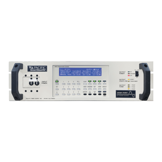
Page 18: Figure 1.3 Amx-Series Power Source - Front View
SECTION 2 SPECIFICATIONS 2.1.1 INPUT POWER REQUIREMENTS (cont.) MODEL 160-AMX INPUT VOLTAGE The Model 160-AMX accepts one of the following three phase input voltages: 208 VAC ∆ ±10%, 47-63 Hz (360-440 Hz cost option) 220 VAC ∆ ±10%, 47-63 Hz (360-440 Hz cost option) 240 VAC ∆... - Page 19 SECTION 2 SPECIFICATIONS (THIS PAGE INTENTIONALLY BLANK)
- Page 20 SECTION 2 SPECIFICATIONS MODEL 305-AMX INPUT VOLTAGE The Model 305-AMX accepts one of the following single phase input voltages: 110 VAC ±10%, 47-63 Hz (360-440 Hz optional) 120 VAC ±10%, 47-63 Hz (360-440 Hz optional) 220 VAC ±10%, 47-63 Hz (360-440 Hz optional) 230 VAC ±10%, 47-63 Hz (360-440 Hz optional) 240 VAC ±10%, 47-63 Hz (360-440 Hz optional) INPUT CURRENT...
-
Page 24: Output Power
SECTION 2 SPECIFICATIONS 2.1.2 OUTPUT POWER OUTPUT VOLTAGE RANGE DIRECT-COUPLED The standard output voltage range of the AMX-Series Power Source is 0-135 VAC (0-150 VAC for the Model 125-AMX) when operated in the direct-coupled mode. Additionally, the Models 112-AMX and 312- AMX can be configured for several direct-coupled output voltage ranges between and including 0-110 VAC and 0-150 VAC . -
Page 30: Figure 2.1.2(B) Model 108-Amx Output Derating Curves
SECTION 2 SPECIFICATIONS FIGURE 2.1.2(E2) MODEL 160-AMX OUTPUT DERATING CURVES... -
Page 31: Figure 2.1.2(C) Model 112-Amx Output Derating Curves
SECTION 2 SPECIFICATIONS (THIS PAGE INTENTIONALLY BLANK) -
Page 43: Dimensions
SECTION 2 SPECIFICATIONS 2.2.1 DIMENSIONS (cont.) MODEL 140-AMX Power Source: Height: 14.00" [356 mm] Width: 19.00" [483 mm] (front panel); 17.00" [432 mm] (chassis) Depth: 23.50" [597 mm] Weight: 170 lbs. [77 kg] Refer to Figure 2.2.3 for the outline drawing of the Model 140-AMX. MODEL 160-AMX Power Source: Height:... - Page 44 SECTION 2 SPECIFICATIONS MODEL 312-AMX Height: 5.25" [134 mm] Width: 19.00" [483 mm] (front panel); 16.75" [426 mm] (chassis) Depth: 23.00" [584 mm] (measured from back side of front panel, excludes terminal blocks) Weight: 70 lbs. [32 kg] Refer to Figure 2.2.1 for the outline drawing of the Model 312-AMX.
- Page 45 SECTION 2 SPECIFICATIONS (THIS PAGE INTENTIONALLY BLANK)
-
Page 50: Figure 2.2.3 Outline Drawing, Models 125, 140, 160, 345, & 360-Amx
SECTION 2 SPECIFICATIONS FIGURE 2.2.3 OUTLINE DRAWING, MODELS 125, 140, 160, 345, & 360-AMX... -
Page 52: Output Power Connection
2.2.4 CHASSIS SLIDE MOUNTS The chassis of the AMX-Series Power Source is designed to accept slide rails. These are provided as a cost option. For more information, contact your local sales representative or the Pacific Power Source Sales Office. ENVIRONMENTAL SPECIFICATIONS This paragraph lists the environmental requirements of the AMX-Series Power Source. -
Page 53: Installation
SECTION 3 INSTALLATION INSTALLATION This section describes the installation of the AMX-Series AC Power Source. CHASSIS PLACEMENT The AMX-Series Power Source is designed to fit into the standard 19 inch rack. Provisions for mounting slide rails are included in the chassis. The chassis can also be used as a bench-top unit, if desired. * * * W A R N I N G * * * •... -
Page 54: Output Frequency
The front panel alone will not support the weight of the chassis. Chassis slides are available from Pacific Power Source as a cost option. Call factory service for details. After the location for the chassis is selected, verify that the input voltage of the power source is correct (Input voltage is stated on the system ID label). -
Page 55: Output Voltage Range Configuration
SECTION 3 INSTALLATION OUTPUT VOLTAGE RANGE CONFIGURATION This paragraph describes the configuration of the Output Voltage Range for the AMX-Series Power Source. The AMX-Series Power Source can be configured for several different Output Voltage Ranges. The standard output configurations are: 0-110 VAC Direct-Coupled Output on 112-AMX and 312-AMX 0-125 VAC... -
Page 68: Figure 3.2.7 Models 140, 160, 345, 360, 390, & 3120-Amx Output Voltage Configuration
SECTION 3 INSTALLATION FIGURE 3.2.7 MODELS 140, 160, 345, 360, 390, & 3120-AMX OUTPUT VOLTAGE CONFIGURATION... - Page 69 The Transformer Ratio Switch of the UPC is set to 0.0 on systems without transformer-coupled outputs. While the above procedure can be performed in the field, Pacific Power Source recommends that the system be returned to the factory when transformer-coupled outputs are to be added to the system. This insures proper...
-
Page 78: Figure 3.3.7 Models 140, 160, 345, 360, 390, 3120-Amx Input Voltage
SECTION 3 INSTALLATION FIGURE 3.3.7 MODELS 140/160/345/360/390/3120-AMX INPUT VOLTAGE CONFIGURATION... - Page 79 SECTION 3 INSTALLATION 3.3.7 INPUT VOLTAGE CONFIGURATION, MODELS 140-AMX, 160-AMX, 345-AMX, 360-AMX, 390-AMX, & 3120-AMX * * * W A R N I N G * * * • DISCONNECT THIS UNIT FROM THE INPUT SERVICE BEFORE REMOVING TOP COVER. HIGH VOLTAGE HAZARD PRESENT INSIDE UNIT WHEN TOP COVER IS REMOVED AND STILL CONNECTED TO INPUT SERVICE.
-
Page 80: Figure 3.3.8 Amx-Series Input Wiring Diagram
SECTION 3 INSTALLATION FIGURE 3.3.8 AMX-SERIES INPUT WIRING DIAGRAM... -
Page 81: Input Power Wiring Requirements
SECTION 3 INSTALLATION 3.3.8 INPUT POWER WIRING REQUIREMENTS This paragraph describes the input wiring requirements for the AMX-Series Power Sources. Wire size and connection techniques are discussed. * * * W A R N I N G * * * •... -
Page 82: Figure 3.4.1.1 Single Phase Output Connection
SECTION 3 INSTALLATION FIGURE 3.4.1.1 SINGLE PHASE OUTPUT CONNECTION... -
Page 86: Figure 3.4.2.1 Split Phase Output Connection
SECTION 3 INSTALLATION FIGURE 3.4.2.1 SPLIT PHASE OUTPUT CONNECTION... -
Page 98: Figure 3.8.1 External Sense Connection, Models 125, 140, 160, 345, 360, 390, & 3120-Amx
SECTION 3 INSTALLATION FIGURE 3.8.1 EXTERNAL SENSE CONNECTION, MODELS 125, 140, 160, 345, 360, 390, & 3120-AMX... -
Page 103: Operation
SECTION 4 OPERATION SECTION 4 OPERATION OPERATION This section describes the operation of an AMX-Series AC Power Source. The procedure described in the following paragraphs is a general procedure common to all systems (except as noted). This procedure does not detail operation of a specific controller. -
Page 111: System Architecture
SECTION 4 OPERATION 4.6.1 SYSTEM ARCHITECTURE The AMX-Series Power Source output can be configured for single, split, and three phase voltage forms. Figure 4.6.1 is a simplified block diagram of the possible output architectures. Only the direct-coupled output forms are shown. All of the forms can be supplied with transformers to raise the output voltage level. The 1 PHASE mode of operation is a one vector output form. -
Page 113: Maintenance
SECTION 5 MAINTENANCE MAINTENANCE This section describes the maintenance of the AMX-Series AC Power Source. MAINTENANCE INTERVAL Maintenance of the Models 105-AMX, 108-AMX, 112-AMX, 305-AMX, 308-AMX, and 312-AMX Power Sources is required once every six months and consists of performing regular calibration. Maintenance of the Models 125-AMX, 140-AMX, 160-AMX, 320-AMX, 345-AMX, 360-AMX, 390-AMX, and 3120-AMX Power Sources is required once every three months and consists of checking/cleaning the fan filter, with regular calibration once every six months. -
Page 115: Calibration
SECTION 6 CALIBRATION CALIBRATION This section describes the calibration of the AMX-Series AC Power Source. CALIBRATION INTERVAL The AMX-Series Power Source requires calibration once every six months or after service has been performed to the system. TEST EQUIPMENT REQUIREMENTS The test equipment listed below is required for calibration of the AMX-Series Power Source. Digital Voltmeter: 4½... - Page 119 Model. When questions regarding operation arise or service is required, call the factory for instructions. Pacific Power Source maintains a staff of highly trained technicians who are ready to assist. The phone number to call is (949) 251-1800.
- Page 123 SECTION 7 SERVICE 7.3.5A FACTORY PART NUMBERS, MODEL 160-AMX SUB-ASSEMBLY FACTORY PART No. Control/Metering PCB: 134170 Input Filter PCB: 134175 Voltage Amplifier PCB: 134171 or 134176 Input Filter PCB: 134177 External Sense Filter PCB: 134178 Output Filter PCB: 134179 Power Amplifier PCB: 134477 LED Display PCB: 139071...
- Page 124 SECTION 7 SERVICE THIS PAGE INTENTIONALLY LEFT BLANK 108B...
- Page 148 INDEX Airflow Grounding requirements Clearances 3φ output delivery Split φ output AM inputs 1φ output UMC-311 transformer-coupled outputs Ammeter Indicators UMC-311 Output Coupling Amps to Volts Ratio setting Output Form AUX I/O Output ON/OFF mating connector Shutdown 89,93,94 signal level Input current UMC-31, detailed1 105-AMX...
- Page 153 ERRATA 11/17/04 FOR THE AMX-SERIES OPERATION MANUAL DOCUMENT 139250 The following lists changes to the manual. The information which follows takes precedence over that originally given. NOTE ON ETL LISTED SYSTEMS, Models 105, 108, 112, 305, 308, and 312-AMX: An Input Power Cord plug is now provided since ETL/UL considers these models to be of the "portable" class.
-
Page 154: Output Voltage Range Configuration
PAGE 11; PARAGRAPH 2.1.1 INPUT POWER REQUIREMENTS, MODEL 320-AMX Changes due to ETL listing and CE-mark requirements. Service Recommended matched to Input Circuit Breaker amperage rating. WAS: INPUT CURRENT 220/380 VAC 6 Arms; 10 A Service Recommended 240/416 VAC 5 Arms; 10 A Service Recommended 277/480 VAC 5 Arms;... -
Page 155: System Architecture
WAS: “This paragraph describes the configuration of the Output Voltage Range for the Models 140, 160, 345, 360, 390, and 3120-AMX Power Sources. … A Magnetics Module ( Assembly No. 134310) is required for the 204, 273 and 341 VAC output forms.” “This paragraph describes the configuration of the Output Voltage Range for the Models 140, 160, 320, 345, 360, 390, and 3120-AMX Power Sources. -
Page 156: Factory Part Numbers, Model 105-Amx
WAS: “The 3 PHASE mode of operation is a three vector output form with vectors normally separated by 120°. … The voltage ranges of the various transformer output forms are: VR1.5 - 0 to 204/353 VAC (Models 305, 308, 345, 360, 390, and 3120-AMX), VR2.0 - 0 to 273/473 VAC (Models 305, 308, 345, 360, 390, and 3120-AMX), and VR2.5 - 0 to 341/591 VAC (Models 305, 308, 345, 360, 390, and 3120-AMX).”... -
Page 157: Factory Part Numbers, Model 125-Amx
PAGE 108; PARAGRAPH 7.3.4 FACTORY PART NUMBERS, MODEL 125-AMX Changes due to ETL listing and CE-mark requirements. WAS: CHASSIS COMPONENT FACTORY PART No. Input Circuit Breaker: 716059 Input and Output Terminal Blocks: 705009 SUB-ASSEMBLY FACTORY PART No. LVPS Fuse PCB: 140374 (NEW) CHASSIS COMPONENT... -
Page 158: Factory Part Numbers, Model 320-Amx
PAGE 111; PARAGRAPH 7.3.9 FACTORY PART NUMBERS, MODEL 320-AMX Changes due to ETL listing and CE-mark requirements. WAS: CHASSIS COMPONENT FACTORY PART No. Input Circuit Breaker: 716059 Output Terminal Block: 705009 (black case) Output Contactor: 717038 SUB-ASSEMBLY FACTORY PART No. LVPS Fuse PCB: 140373 (New)