Table of Contents
Advertisement
Quick Links
Instructions - Parts
Pro
Pro Xp™
Pro
Xp™ 60
Xp™
60
60 WB
An electrostatic
electrostatic air
air spray
spray gun
An
An
electrostatic
air
spray
conditions
conditions for
conditions
for non
for
non- - - flammability
non
flammability listed
flammability
For
For
For professional
professional use
professional
use only.
use
only.
only.
Important
Important Safety
Important
Safety Instructions
Safety
Read all warnings and instructions in this manual and in the isolation
system manual before using the equipment. Save
100 psi (0.7 MPa, 7.0 bar) Maximum
Fluid Working Pressure
100 psi (0.7 MPa, 7.0 bar) Maximum Air
Working Pressure
See page 3 for model part numbers and
approval information.
WB Gun
WB
Gun
Gun
gun for
for spraying
spraying conductive,
conductive, waterborne
gun
for
spraying
conductive,
listed on
listed
on page
on
page 3. 3. 3.
page
Instructions
Instructions
PROVEN QUALITY. LEADING TECHNOLOGY.
waterborne fluids
fluids that
waterborne
fluids
Save these
Save
these instructions.
these
instructions.
instructions.
3A7504A
that meet
meet at at at least
least one
one of of of the
that
meet
least
one
EN
the
the
Advertisement
Table of Contents
Troubleshooting

Related Manuals for Graco Pro Xp 60 WB


Summary of Contents for Graco Pro Xp 60 WB
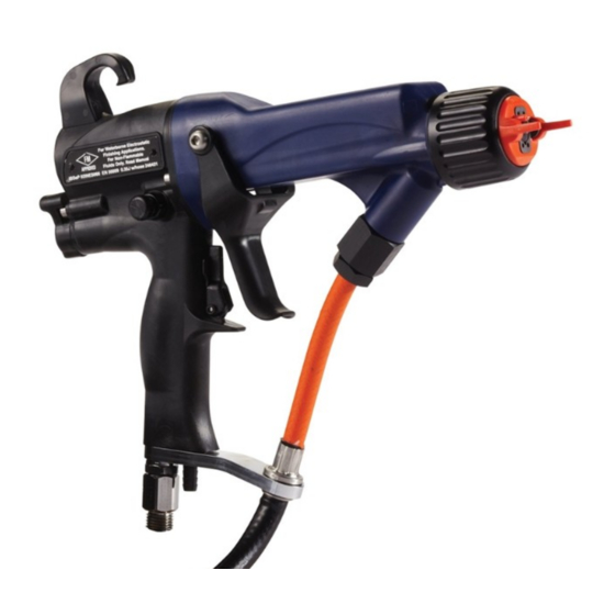
- Page 1 Instructions - Parts Pro Xp™ Xp™ Xp™ 60 60 WB WB Gun 3A7504A An electrostatic electrostatic air air spray spray gun gun for for spraying spraying conductive, conductive, waterborne waterborne fluids fluids that that meet meet at at at least least one one of of of the electrostatic...
-
Page 2: Table Of Contents
Technical Specifications........94 Prepare the Gun for Service ......48 Air Cap and Nozzle Replacement....49 California Proposition 65 ........94 Air Cap, Spray Tip, and Nozzle Notes ..............95 Replacement (Model L60M19) ........50 Graco Pro Xp Warranty ........96 3A7504A... -
Page 3: Models
Model Description Description Description L60T18 Pro Xp 60 WB Standard Electrostatic Air Spray Gun, for waterborne coatings. L60M18 Pro Xp 60 WB Smart Electrostatic Air Spray Gun, for waterborne coatings. L60M19 Pro Xp 60 Smart Electrostatic Air Spray Gun, for mold release applications. -
Page 4: Warnings
• Only use non-flammable solvents when flushing or cleaning equipment. • Only use the red-colored Graco electrically conductive gun air hose with this gun. Do not use black or gray-colored Graco air hoses. • Do not use pail liners unless they are conductive and grounded. - Page 5 • Interlock the gun air supply with the voltage isolation system to shut off the air supply anytime the isolation system enclosure is opened. • Only use the red-colored Graco electrically conductive gun air hose with this gun. Do not use black or gray-colored Graco air hoses.
- Page 6 Warnings WARNING WARNING WARNING EQUIPMENT EQUIPMENT EQUIPMENT MISUSE MISUSE HAZARD MISUSE HAZARD HAZARD Misuse can cause death or serious injury. • Do not operate the unit when fatigued or under the influence of drugs or alcohol. • Do not exceed the maximum working pressure or temperature rating of the lowest rated Technical Specifications Specifications in all equipment manuals.
-
Page 7: Gun Overview
Gun Overview Gun Overview Overview Overview How the the Electrostatic Electrostatic Spray Spray Gun Spraying Waterborne Waterborne Fluids Fluids Electrostatic Spray Spraying Spraying Waterborne Fluids Works Electrostatically Works Works Electrostatically Electrostatically The air hose supplies air to the spray gun. Part of the This electrostatic air spray gun is designed to only waterborne fluids which meet one of the air operates the alternator turbine and the rest of the... - Page 8 Description Description Description Purpose Purpose Purpose Air Swivel Inlet 1/4 npsm(m) left-hand thread, for Graco red-colored grounded air supply hose. Fluid Inlet Graco waterborne fluid supply hose Turbine Air Exhaust Barbed fitting, for supplied exhaust tube. Air Cap and Nozzle...
-
Page 9: Smart Guns
Gun Overview Smart Guns Guns Smart Smart Guns Voltage Adjustment Adjustment Switch Switch Voltage Voltage Adjustment Switch The Smart Gun module displays spraying voltage, current, alternator speed, and the voltage setting (low or high). It also allows the user to change to a lower The voltage adjustment switch (VA) allows the spraying voltage. - Page 10 Gun Overview Error Error Error Display Display Display Note After 2 seconds of inactivity the display will If the Smart module loses communication with the return to the Operating Screen. power supply, the Error display appears, the Hz indicator turns red, and the Smart module is disabled. Note See the following figure and Smart Gun Key, page...
- Page 11 Gun Overview Smart Smart Smart Gun Gun Key Table Table 1 1 1 Key Table Key for for Figures Figures Figures 2–9 2–9 2–9 Item Item Item Description Description Description Purpose Purpose Purpose Voltage Adjustment Switch Two-position switch sets Smart gun voltage to low setting (LO) or high setting (HI).
- Page 12 Gun Overview Diagnostic Diagnostic Diagnostic Mode Mode Mode Diagnostic Mode includes four screens which display and hold for approximately 5 seconds to return to gun data: Operating Mode. • Voltage (kiloVolts) Screen • Current (microAmperes) Screen • Alternator Speed (Hertz) Screen •...
- Page 13 Gun Overview Alternator Alternator Alternator Speed Speed (Hertz) Speed (Hertz) (Hertz) Screen Screen Screen Low Voltage Voltage Lock Voltage Lock Screen Lock Screen Screen The Alternator Speed (Hertz) Screen is the third The Low Voltage Lock Screen is the fourth screen in screen in the Diagnostic Mode.
-
Page 14: Installation
It is not an actual • An isolation enclosure that prevents persons from system design. For assistance in designing a system to suit your particular needs, contact your Graco making contact with the high voltage components before the system voltage is discharged. All distributor. -
Page 15: Typical Installation
Main Air Supply Line GND* Gun Air Hose Ground Wire Bleed-Type Air Shutoff Valve Strain Relief Fitting Graco Red Grounded Air Hose (left-hand Graco Waterborne Fluid Hose threads) * These items are required for safe operation. Isolated System Gun Air Pressure Regulator... - Page 16 Connect Waterborne Fluid Hose 3. A new Graco waterborne fluid hose comes fully assembled and ready to install. For fluid hose assembly and repair instructions, refer to Always use a Graco waterborne fluid hose between Fluid Hose Assembly and Repair, page the voltage isolation system fluid outlet and the gun fluid inlet.
- Page 17 (PR) on the gun air supply line to Graco Grounded Air Hose for the gun air supply. control air pressure to the gun. • Do not use the black or gray-colored Graco air 3. Connect the red-colored Graco Electrically hoses.
-
Page 18: Connect The Waterborne Fluid Hose
Air compressors: • Ground the equipment according the conductive gloves supplied with the gun. If to the manufacturer's recommendations. non-Graco gloves are worn, cut off fingers or palm area of gloves to ensure your hand contacts the grounded gun handle. 3A7504A... - Page 19 Installation All air lines All solvent pails: • must be properly grounded. Use only • Use only approved, grounded grounded hoses with a maximum of 100 feet (30.5 metal containers, which are conductive. Do not m) combined hose length to ensure grounding use plastic containers.
-
Page 20: Gun Setup
Gun Setup Gun Setup Setup Setup Gun Setup Setup Procedure Procedure Setup Procedure For additional steps to set up specialty guns, Soft Spray Gun Setup Procedure, page Round Spray Gun Setup Procedure, page HVLP Gun Setup Procedure, page Abrasive Material Gun Setup Procedure, page To reduce the risk of fire and explosion, fluids used Mold Release Gun Setup Procedure, page must meet the following flammability requirements:... - Page 21 5. Connect the waterborne hose. Follow the steps counterclockwise. Connect the Waterborne Fluid Hose, page 6. Connect the red Graco grounded air hose to the gun air inlet. The gun air inlet fitting has left-hand threads. Follow the steps in Air Supply Line, page 7.
- Page 22 Gun Setup 14. Fully open the atomizing air restrictor valve (G) 16. Set the gun air regulator to deliver a minimum clockwise. 45 psi (0.32 MPa, 3.2 bar) at the gun when triggered, to ensure full spraying voltage. Table Table Table 2 2 2 Pressure Pressure Pressure Drop...
- Page 23 Gun Setup 18. Shut off the air to the gun. Turn OFF (O) the ES 21. Spray a test pattern. Check the atomization. On-Off switch (J). • If over-atomization occurs at minimum pressure, adjust the atomizing air restrictor valve. • If atomization is inadequate, increase air pressure or decrease fluid flow.
- Page 24 Gun Setup Soft Spray Spray Gun Gun Setup Setup Procedure Procedure Soft Soft Spray Setup Procedure To convert a gun to achieve a soft spray pattern for Table Table Table 4 4 4 Pressure Pressure Pressure Drop Drop Drop small or lightweight parts, do the following: Air Hose Hose Hose...
-
Page 25: Procedure
Gun Setup HVLP Gun Gun Setup Setup Procedure Procedure HVLP HVLP Setup Procedure To spray high pressure low volume (HVLP) spray c. Turn ON (I) the ES On-Off switch (J). guns, air pressure at the air cap must be 10 PSI (0.07 MPa, 0.7 bar) or less. - Page 26 Gun Setup Round Spray Spray Gun Gun Setup Setup Procedure Procedure Round Round Spray Setup Procedure Table 7 7 7 LED LED Indicator Indicator Colors Colors Table Table Indicator Colors Indicator Description Indicator Indicator Description Description To achieve a round spray pattern, do the following: Color Color Color...
- Page 27 Gun Setup 5. Turn ON (I) the ES On-Off switch (J). 7. Verify that the ES indicator (K) [Hz indicator on Smart guns] is lit. Table 9 9 9 LED LED Indicator Indicator Colors Colors Table Table Indicator Colors Indicator Description Indicator Indicator...
- Page 28 Gun Setup Abrasive Material Material Gun Gun Setup Setup Abrasive Abrasive Material Setup 10. Turn on the air to the gun. Turn ON (I) the ES On-Off switch (J). Procedure Procedure Procedure To extend wear life, perform the following tasks each day: •...
- Page 29 Gun Setup 4. Turn on the air to the gun. Turn ON (I) the ES 6. Adjust the fan air adjustment valve. On-Off switch (J). • Fully open the fan air adjustment valve, counterclockwise, for the longest pattern. • Turn the valve clockwise to restrict the fan air and create a shorter pattern.
- Page 30 Spray Tip Selection Chart (Model L60M19 MRG Gun Only), page 86, or consult with your Graco distributor. To install the tip, see Air Cap, Spray Tip, and Nozzle Replacement (Model L60M19), page 2. Follow steps 2–10 in the Gun Setup Procedure, page 3.
- Page 31 Gun Setup 12. Set the gun air regulator to deliver a minimum 13. Turn the atomizing air adjustment valve of 45 psi (0.32 MPa, 3.2 bar) at the gun when counterclockwise until any tails disappear. triggered, to ensure full spraying voltage. See the table below.
-
Page 32: Check Gun Electrical Grounding
Failure to follow this warning could cause fire, explosion, and electric shock and result in serious injury and property damage. Graco Part No. 241079 Megohmmeter is available as an accessory to check that the gun is properly grounded. Figure 14 Check Gun Electrical Grounding 7. -
Page 33: Operation
Operation Operation Operation Operation Pressure Relief Relief Procedure Procedure Fluid Voltage Voltage Discharge Discharge and Pressure Pressure Relief Procedure Fluid Fluid Voltage Discharge Grounding Procedure Procedure Grounding Grounding Procedure This equipment stays pressurized until pressure is manually relieved. To help prevent serious The fluid supply is charged with high voltage until injury from pressurized fluid, such as splashing, the voltage is discharged. -
Page 34: Startup
See Grounding, page ⃞ The Graco waterborne fluid hose is in good To reduce the risk of an injury, follow the condition with no cuts or abrasions of the PTFE... -
Page 35: Maintenance
Maintenance Maintenance Maintenance Maintenance Flushing Flushing Flushing • Flush before changing fluids, before fluid can dry in the equipment, at the end of the day, before storing, and before repairing equipment. To reduce the risk of an injury, follow the Pressure Relief Procedure, page 33, whenever •... - Page 36 Maintenance 1. Turn OFF (O) the ES On-Off switch. Wait 30 7. Leave the flushing fluid in the system until you seconds for the voltage to bleed off. are ready to spray again. 8. Hang the gun from its hook, with the nozzle pointing down.
- Page 37 Maintenance 4. Clean the outside of the gun with a non-flammable 5. Remove the air cap. solvent, as defined under Flushing, page Use a soft cloth. Point the gun down to prevent solvent from entering the gun passages. Do not immerse the gun.
-
Page 38: Daily System Care
Maintenance Daily System System Care Care Daily Daily System Care 5. Check the movement of the trigger and valves. Lubricate if necessary. 1. Follow the Pressure Relief Procedure, page Check Gun Electrical Grounding, page 2. Clean the fluid and air filters. 7. -
Page 39: Electrical Tests
Voltage Loss Troubleshooting, page 41 for other possible causes of poor performance, or contact your Graco distributor. Megohmmeter Part No. 241079 is not approved for use in a hazardous area. (In Figure 15, item AA.) To reduce the risk of sparking, do not use... -
Page 40: Test Power Supply Resistance
4. If in range, go to Electrical Troubleshooting, page 46, for other possible causes of poor performance, or contact Figure 18 Electrode your Graco distributor. 5. Remove the electrode (3), see Electrode Replacement, page 52. Measure the resistance between the contact (HH) and the electrode wire (GG). -
Page 41: Troubleshooting
Troubleshooting Troubleshooting Troubleshooting Troubleshooting are electrically connected through the conductive, waterborne fluid. Before troubleshooting or servicing the voltage isolation system itself, you need to determine which component in the system is most likely causing a Installing and servicing this equipment requires problem. - Page 42 Troubleshooting Visual Visual Visual Checks Checks Checks Tests Tests Tests First, check the system for any visible faults or errors If you still have no voltage, separate the spray gun to help isolate whether the spray gun, fluid hose or and hose from the voltage isolation system and voltage isolation system has failed.
- Page 43 Troubleshooting 11. A dielectric breakdown is most likely in one of the following three areas. Repair or replace the component that is failing. a. Fluid hose: • Check for leakage or any bulges in the outer cover, which may indicate a pin-hole leak through the PTFE layer.
-
Page 44: Spray Pattern Troubleshooting
Troubleshooting Spray Pattern Pattern Troubleshooting Troubleshooting Spray Spray Pattern Troubleshooting Check all possible remedies in the Troubleshooting Some spray pattern problems are caused by the Chart before disassembling the gun. improper balance between air and fluid. Problem Problem Problem Cause Solution Cause Cause... -
Page 45: Gun Operation Troubleshooting
Troubleshooting Gun Operation Operation Troubleshooting Troubleshooting Operation Troubleshooting Problem Problem Problem Cause Cause Cause Solution Solution Solution Excessive spray fog. Atomizing air pressure too high. Close restrictor valve part way, or decrease air pressure as low as possible; minimum 45 psi (0.32 MPa, 3.2 bar) needed at gun for full voltage. -
Page 46: Electrical Troubleshooting
Troubleshooting Electrical Troubleshooting Troubleshooting Electrical Electrical Troubleshooting Problem Problem Problem Cause Cause Cause Solution Solution Solution Voltage still present at ES On/Off switch is not turned Turn OFF (O). gun after following the OFF (O). Fluid Voltage Discharge and Did not wait long enough for Wait longer before touching Grounding Procedure, page voltage to discharge. - Page 47 Troubleshooting Problem Cause Solution Problem Problem Cause Cause Solution Solution Operator gets mild shock. Operator not grounded or is near Grounding, page ungrounded object. Gun not grounded. Check Gun Electrical Grounding, page 32, and Test Gun Resistance, page Operator gets shock from Workpiece not grounded.
-
Page 48: Repair
• Follow the Fluid Voltage Discharge and • Only use genuine Graco parts. Do not mix or use Grounding Procedure, page 33, and turn OFF parts from other Pro Gun models. (O) the ES On-Off switch before flushing, •... -
Page 49: Prepare The Gun For Service
(4a) except to replace it. Never operate the gun without the contact ring in place. Do not replace the contact ring with anything but a genuine Graco part. Note Use non-silicone grease, Part No. - Page 50 Repair Air Cap, Cap, Spray Spray Tip, Tip, and and Nozzle Nozzle Replacement Replacement (Model (Model L60M19) L60M19) Cap, Spray Tip, Nozzle Replacement (Model L60M19) 1. Follow the steps in 3. Disassemble the air cap assembly. Check the Prepare the Gun for Service, page condition of the u-cup (6a), electrode (5a), o-ring (5b), and tip gasket (10a).
- Page 51 (6). The lips of the u-cup must face the gun without the conductive ring in place. forward. Do not replace the conductive ring with anything but a genuine Graco part. NOTICE NOTICE NOTICE 5. Trigger the gun and remove the nozzle (4), using To avoid damaging the tip guard, orient the an adjustable wrench.
-
Page 52: Air Cap And Nozzle Replacement
Repair Electrode Replacement Replacement Needle Replacement Replacement (Model (Model L60M19) L60M19) Electrode Electrode Replacement Needle Needle Replacement (Model L60M19) 1. Follow the steps in 1. See Prepare the Gun for Service, page Prepare the Gun for Service, page 2. Remove the air cap and nozzle. See 2. -
Page 53: Packing Rod Repair
Repair Fluid Packing Packing Rod Rod Removal Removal Packing Rod Rod Repair Repair Fluid Fluid Packing Removal Packing Packing Repair 1. Follow the steps in Replace the packing rod as individual parts or as an Prepare the Gun for Service, page assembly. - Page 54 Repair Reassemble Reassemble Reassemble the the Packing Packing Packing Rod Before installing the fluid packing rod into the gun 4. Lightly tighten the packing nut (2f). The packing barrel, make sure the internal surfaces of the barrel nut is properly tightened when there is 3 lb (13.3 are clean.
-
Page 55: Barrel Removal
Repair Barrel Removal Removal Barrel Installation Installation Barrel Barrel Removal Barrel Barrel Installation 1. Follow the steps 1. Be sure the gasket (28*) and grounding spring Prepare the Gun for Service, page (18) are in place. Make sure the gasket air holes are aligned properly. -
Page 56: Barrel Installation
Repair Power Supply Supply Removal Removal and and Replacement Replacement Power Power Supply Removal Replacement • Inspect the gun handle power supply cavity for dirt 9. Insert the power supply/alternator assembly in or moisture. Clean with a clean, dry rag. the gun handle (16). -
Page 57: Repair
Repair Alternator Removal Removal and and Replacement Replacement Alternator Alternator Removal Replacement Replace alternator bearings after 2000 hours of 6. Push the fan and coil assembly (15a) out the operation. Order Part No. 24N706 Bearing Kit. Parts front of the housing (15d). included in the kit are marked with a symbol (♦). - Page 58 Repair 12. Hold the coil assembly (15a) on a workbench 14. Rotate the fan (15e) so its blades clear the four with the fan end facing up. Press the fan (15e♦) bearing tabs (T) at the back of the housing. onto the long end of the shaft (S).
- Page 59 Repair Fan Air Air Adjustment Adjustment Valve Valve Repair Repair Adjustment Valve Repair 1. Follow the steps in 8. Reassemble the retaining ring (30d). Unscrew Prepare the Gun for Service, page the valve stem from the housing until it is stopped by the retaining ring.
- Page 60 Repair Atomizing Air Air Restrictor Restrictor Valve Valve Repair Repair Atomizing Atomizing Restrictor Valve Repair 1. Follow the steps in Prepare the Gun for Service, page 2. Place a wrench on the flats of the valve housing (29a) and unscrew the valve from the handle (16).
- Page 61 Repair ES On On - - - Off Off and and Fluid Fluid Adjustment Adjustment Valve Valve Repair Repair Fluid Adjustment Valve Repair 1. Follow the steps in 4. Clean and inspect parts for damage. Replace Prepare the Gun for Service, page if necessary.
-
Page 62: Air Valve Repair
Repair Air Valve Valve Repair Repair Valve Repair 1. Follow the steps in Prepare the Gun for Service, page 2. Follow the steps in Barrel Removal, page 3. Remove the screws (13) and trigger (12). 4. Remove the ES On-Off Valve. See ES On-Off and Fluid Adjustment Valve Repair, page 5. -
Page 63: Replacement
Repair 2. To replace the air exhaust valve: a. Remove the clamp (43) and the exhaust tube (36). b. Unscrew the swivel (21) from the gun handle (16). The swivel is a left-hand thread. Remove the bracket (104). c. Pull the exhaust valve (19) from the handle (16). -
Page 64: Parts
Parts Parts Parts Parts Standard Waterborne Waterborne Air Air Spray Spray Gun Gun Assembly Assembly Standard Standard Waterborne Spray Assembly Part No. No. L60T18 L60T18 60 60 kV kV Electrostatic Electrostatic Waterborne Waterborne Air Air Spray Spray Gun, Gun, Series Series D D D Part Part... -
Page 65: Assembly
Parts Part No. No. L60T18 L60T18 60 60 kV kV Electrostatic Electrostatic Waterborne Waterborne Air Air Spray Spray Gun, Gun, Series Series D D D Part Part L60T18 Electrostatic Waterborne Spray Gun, Series Includes items 1–50. Part No. Description Part No. Description Ref. - Page 66 Parts Smart Waterborne Waterborne Air Air Spray Spray Gun Gun Assembly Assembly Smart Smart Waterborne Spray Assembly Part Part Part No. No. L60M18 L60M18 60 L60M18 60 kV kV Electrostatic Electrostatic Waterborne Electrostatic Waterborne Waterborne Air Air Spray Spray Gun, Spray Gun, Gun, Series...
- Page 67 Parts Part No. No. L60M18 L60M18 60 60 kV kV Electrostatic Electrostatic Waterborne Waterborne Air Air Spray Spray Gun, Gun, Series Series D D D Part Part L60M18 Electrostatic Waterborne Spray Gun, Series Includes items 1-50. Part No. Description Part No. Description Ref.
- Page 68 Parts Mold Release Release Smart Smart Air Air Spray Spray Gun Gun Assembly Assembly Mold Mold Release Smart Spray Assembly Part Part Part No. No. L60M19 L60M19 L60M19 60 60 kV kV Electrostatic Electrostatic Mold Electrostatic Mold Release Mold Release Release Air Air Spray Spray Gun,...
- Page 69 Parts Part No. No. L60M19 L60M19 60 60 kV kV Electrostatic Electrostatic Mold Mold Release Release Air Air Spray Spray Gun, Gun, Series Series D D D Part Part L60M19 Electrostatic Mold Release Spray Gun, Series Ref. Ref. Ref. Part Part No.
- Page 70 Parts Packing Rod Rod Assembly Assembly Packing Packing Assembly Part Part Part No. No. 24N655 24N655 Packing 24N655 Packing Packing Rod Rod Assembly Assembly Assembly Includes items 2a-2k Part No. Description Part No. Description Ref. Ref. Ref. Part Part Description Description Ref.
-
Page 71: Alternator Assembly
Parts Alternator Assembly Assembly Alternator Alternator Assembly Part Part No. Part No. 24N664 24N664 Alternator 24N664 Alternator Alternator Assembly Assembly Assembly Ref. Ref. Ref. Part Part Part Description Description Description Ref. Ref. Ref. Part Part Part Description Description Description — — — 24N705 COIL, alternator 15e♦... - Page 72 Parts ES On On - - - Off Off and and Fluid Fluid Adjustment Adjustment Valve Valve Fluid Adjustment Valve Part Part Part No. No. 24N630 24N630 24N630 ES ES On-Off On-Off and On-Off and Fluid Fluid Adjustment Fluid Adjustment Adjustment Ref.
-
Page 73: Assembly
Parts Fan Air Air Adjustment Adjustment Valve Valve Assembly Assembly Atomizing Air Air Restrictor Restrictor Valve Valve Adjustment Valve Assembly Atomizing Atomizing Restrictor Valve Assembly Assembly Assembly Part Part No. Part No. 24N634 24N634 24N634 Fan Fan Air Air Adjustment Adjustment Adjustment Valve Valve... -
Page 74: Air Cap Assembly
Parts Air Cap Cap Assembly Assembly Smart Module Module Assembly Assembly Assembly Smart Smart Module Assembly Part Part Part No. No. 24N727 24N727 Air 24N727 Air Cap Cap Assembly Assembly Assembly Part Part No. Part No. 24N756 24N756 Smart 24N756 Smart Smart Module Module... -
Page 75: Round Spray Assembly
Parts Round Spray Spray Assembly Assembly Round Round Spray Assembly Part Part No. Part No. 24N318 24N318 large 24N318 large pattern large pattern pattern Part No. Description Ref. Ref. Ref. Part Part Description Description 24N729 NOZZLE, round spray; in- cludes 4a and 4b. See Fluid Nozzle Selection Chart, page 24N645... - Page 76 Parts Part No. No. 25N836 25N836 small small pattern pattern Part Part 25N836 small pattern Ref. Ref. Ref. Part Part Part No. Description Description Description Part No. No. 25N837 25N837 medium medium pattern pattern Part Part 25N837 medium pattern 25N838 AIR CAP, inner, small pattern;...
- Page 77 Fluid Nozzles Fluid Nozzles Nozzles Fluid Fluid Nozzles Fluid Nozzle Nozzle Selection Selection Chart Chart Fluid Fluid Nozzle Selection Chart To reduce the risk of an injury, follow the Pressure Relief Procedure, page 33, before removing or installing a fluid nozzle and/or air cap. Fluid Fluid Nozzle Fluid...
- Page 78 Fluid Nozzles Fluid Nozzle Nozzle Performance Performance Charts Charts Fluid Fluid Nozzle Performance Charts Use the following procedure to select the proper fluid nozzle for your application. 1. For each fluid nozzle chart, find the point on the 3. From the marked point, move across to the graph corresponding to your desired flow rate vertical scale to find the required fluid pressure.
- Page 79 Fluid Nozzles Table 14 14 . . . Orifice Orifice Size: Size: 1.0 1.0 mm mm (0.040 (0.040 in.) in.) Table 17 17 . . . Orifice Orifice Size: Size: 1.8 1.8 mm mm (0.070 (0.070 in.) in.) Table Table Orifice Size: (0.040...
-
Page 80: Air Caps
Air Caps Air Caps Caps Caps Air Cap Cap Selection Selection Guide Guide Selection Guide Measurements Measurements Measurements All air cap pattern shapes and lengths in the following charts were measured under the following conditions, unless otherwise noted: To reduce the risk of an injury, follow the Note Pressure Relief Procedure, page 33, before... - Page 81 Air Caps Pattern Shape Shape Pattern Pattern Shape Pattern shapes are influenced by the material viscosity, flow rate, and air pressure settings. The gun may not maintain the intended design shape under all conditions. Round patterns patterns have a swirling, slow, round cone pattern for excellent finish and transfer efficiency. •...
- Page 82 Air Caps General Fan Fan Pattern Pattern Air Air Caps: Caps: Descriptions Descriptions General General Pattern Caps: Descriptions Part No. Color Description Guidelines for for Use Part Part Color Color Description Description Guidelines Guidelines 24N477 Black Standard Most versatile air cap. Recommended for most materials and applications. Class A finish.
- Page 83 Air Caps Specialty Fan Fan Pattern Pattern Air Air Caps: Caps: Descriptions Descriptions Specialty Specialty Pattern Caps: Descriptions Part No. Color Description Guidelines for for Use Part Part Color Color Description Description Guidelines Guidelines 25E670 Black Soft Spray For painting small, lightweight parts with a slow-moving spray pattern. Optimized for low production rates.
- Page 84 Air Caps Round Pattern Pattern Air Air Caps: Caps: Descriptions Descriptions Round Round Pattern Caps: Descriptions Part No. Color Description Guidelines for for Use Part Part Color Color Description Description Guidelines Guidelines 24N318 Black Large Conventional round pattern design for larger patterns up to 8 in (20 cm). Swirling, Pattern slow, round cone pattern for excellent finish and transfer efficiency.
-
Page 85: Air Consumption Charts
Air Caps Air Consumption Consumption Charts Charts Consumption Charts Air consumption applies to the complete gun. Key to to to Air Air Consumption Consumption Consumption Charts Charts Charts TEST CONDITIONS: CONDITIONS: Fan valve fully open (unless otherwise noted), atomization valve fully open (unless TEST TEST CONDITIONS:... -
Page 86: Spray Tip Selection Chart (Model L60M19 Mrg Gun Only)
Spray Tip Selection Chart (Model L60M19 MRG Gun Only) Spray Tip Tip Selection Selection Chart Chart (Model (Model L60M19 L60M19 MRG MRG Gun Spray Spray Selection Chart (Model L60M19 Only) Only) Only) AEM Fine Fine Finish Finish Spray Spray Tips Tips Fine Finish... -
Page 87: Round Spray Tips
Spray Tip Selection Chart (Model L60M19 MRG Gun Only) AEF Fine Fine Finish Finish Pre Pre - - - Orifice Orifice Spray Spray Tips Tips Fine Finish Orifice Spray Tips Recommended for high finish quality applications at low and medium pressures. AEF tips have a pre-orifice that assists in atomizing sheer thinning materials, including lacquers. -
Page 88: Repair Kits And Accessories
Repair Kits and Accessories Repair Kits Kits and and Accessories Accessories Repair Repair Kits Accessories Adapter Adapter and Adapter and Fitting Fitting Fitting Accessories Accessories Accessories Part Part No. Part Description Description Description 24N789 Air Seal Repair Kit Part Part Part No. - Page 89 Description See manual 309455. 16P802 English Warning Sign, available at 24R038 Voltage Tester Conversion Kit. no charge from Graco Converts the 245277 Test Fixture for use with the Pro Xp Gun alternator. 16P798 English Daily Care Sign See manual 406999.
- Page 90 Repair Kits and Accessories Hoses Hoses Hoses Grounded Grounded Grounded Air Air Hoses Hoses Hoses Fluid Fluid Hoses Fluid Hoses Hoses 100 psi (0.7 MPa, 7 bar) Maximum Working Pressure 100 psi (0.7 MPa, 7.0 bar) Maximum Working Pressure 0.315 in. (8 mm) ID; 1/4 npsm(f) x 1/4 npsm(f) left-hand thread 1/4 in.
-
Page 91: Fluid Hose Assembly And Repair
Fluid Hose Assembly Repair The Graco shielded waterborne hose has three layers. An outer jacket (FJ), a conductive layer (FC), and an inner FEP tube (FT). The hose must be stripped to the dimensions shown at each end. At At At the... -
Page 92: Ignitability Of Coating Materials
Ignitability of Coating Materials Ignitability of of of Coating Coating Materials Materials Ignitability Ignitability Coating Materials Per EN 50059 From the Physikalisch-Technische Bundesanstalt, Braunschweig, Germany, June 26, 2019. General General General The fire and explosion protection of spraying systems can be facilitated considerably when processing coating materials with a low portion of solvents and a high flash point (generally water-based paints), provided that the spray cloud of the coating materials are considered to be non-ignitable. -
Page 93: Dimensions
Dimensions Dimensions Dimensions Dimensions Gun Model Model Model A, A, A, in. in. in. (mm) (mm) (mm) B, B, B, in. in. in. (mm) (mm) (mm) C, C, C, in. in. in. (mm) (mm) (mm) Weight Weight Weight without without without bracket, oz oz oz (g) -
Page 94: Technical Specifications
0.7 MPa, 7.0 bar: 99.0 dB(A) Air Inlet Fitting 1/4 npsm(m) left-hand thread Fluid Inlet Fitting Custom inlet for Graco waterborne fluid hose. Wetted Parts Gun: Stainless Steel, PEEK, UHMWPE, Fluoroelastomer, Acetal, Nylon, Polyethylene, Tungsten Wire Waterborne Fluid Hose: FEP... -
Page 95: Notes
Notes Notes Notes Notes 3A7504A... - Page 96 Graco, Graco will, for a period of twelve months from the date of sale, repair or replace any part of the equipment determined by Graco to be defective. However, any deficiency in the barrel, handle, trigger, hook, internal power supply, and alternator (excluding turbine bearings) will be repaired or replaced for thirty-six months from the date of sale.
Need help?
Do you have a question about the Pro Xp 60 WB and is the answer not in the manual?
Questions and answers