Table of Contents
Advertisement
Quick Links
Instructions - Parts
WB3000 Isolation
Isolation System
WB3000
WB3000
Isolation
60
60 AA
60
AA
AA WB
WB Gun
WB
Gun
Gun
Air- - - assisted
assisted spray
spray system
system for
Air
Air
assisted
spray
system
meet
meet at at at least
meet
least
least one
one of of of the
one
the conditions
the
For
For
For professional
professional use
professional
use
use only.
only.
only.
Important Safety
Important
Important
Safety
Safety Instructions
Read all warnings and instructions in this manual before using the
Save these
equipment. Save
Save
3000 psi (21 MPa, 210 bar) Maximum
Fluid Working Pressure
100 psi (0.7 MPa, 7 bar) Maximum Air
Working Pressure
See page 3 for model part numbers and
approval information.
System & & & Pro
System
for use
use when
when electrostatically
electrostatically spraying
for
use
when
electrostatically
conditions for
conditions
for non
for
non- - - flammability
non
flammability listed
flammability
Instructions
Instructions
these instructions.
instructions.
these
instructions.
PROVEN QUALITY. LEADING TECHNOLOGY.
Pro Xp™
Xp™
Pro
Xp™
spraying conductive,
conductive, waterborne
spraying
conductive,
listed on
listed
on page
on
page 3. 3. 3.
page
3A2497H
waterborne fluids
fluids that
that
waterborne
fluids
that
EN
Advertisement
Table of Contents
Troubleshooting

Related Manuals for Graco Pro Xp 60 AA WB


Summary of Contents for Graco Pro Xp 60 AA WB
- Page 1 Instructions - Parts WB3000 Isolation Isolation System System & & & Pro Pro Xp™ Xp™ WB3000 WB3000 Isolation System Xp™ 60 AA AA WB WB Gun 3A2497H Air- - - assisted assisted spray spray system system for for use use when when electrostatically electrostatically spraying spraying conductive,...
-
Page 2: Table Of Contents
Contents Contents Contents Models............... 3 Repair..............44 Prepare the Gun for Service ......44 Related Manuals ..........3 Air Cap, Spray Tip, and Fluid Seat Housing Warnings ............4 Replacement ........44 Electrode Replacement ........ 45 Gun Overview ............ 7 Gun Barrel Removal........ -
Page 3: Models
24N550 WB3000 Waterborne Isolation Enclosure for unshielded hoses. Does not include hoses and gun. H60T18 Pro Xp 60 AA WB Standard Electrostatic Air-assisted Spray Gun, for waterborne coatings. H60M18 Pro Xp 60 AA WB Smart Electrostatic Air-assisted Spray Gun, for waterborne coatings. -
Page 4: Warnings
Warnings Warnings Warnings Warnings The following warnings are for the setup, use, grounding, maintenance, and repair of this equipment. The exclamation point symbol alerts you to a general warning and the hazard symbols refer to procedure-specific risks. When these symbols appear in the body of this manual or on warning labels, refer back to these Warnings. - Page 5 • Interlock the gun air supply with the voltage isolation system to shut off the air supply anytime the isolation system enclosure is opened. • Only use the red-colored Graco electrically conductive gun air hose with this gun. Do not use black or gray-colored Graco air hoses.
- Page 6 Warnings WARNING WARNING WARNING EQUIPMENT EQUIPMENT EQUIPMENT MISUSE MISUSE HAZARD MISUSE HAZARD HAZARD Misuse can cause death or serious injury. • Do not operate the unit when fatigued or under the influence of drugs or alcohol. • Do not exceed the maximum working pressure or temperature rating of the lowest rated Technical Specifications Specifications in all equipment manuals.
-
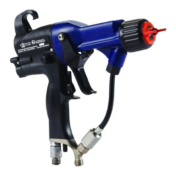
Page 7: Gun Overview
29 before approaching the front of the gun. adjustment to narrow the pattern width. The Graco warranty and approvals are void if the The high working fluid pressure of this gun provides electrostatic spray gun is connected to a non-Graco the power needed to atomize higher solids materials. -
Page 8: Controls, Indicators, And Components
Description Description Description Purpose Purpose Purpose Air Swivel Inlet 1/4 npsm(m) left-hand thread, for Graco red-colored grounded air supply hose. Fluid Hose Graco waterborne fluid hose Turbine Air Exhaust Barbed fitting, for supplied exhaust tube. Air Cap/Tip Guard Spray Tip Selection Chart, page 68, for available sizes. -
Page 9: Smart Guns
Gun Overview Smart Guns Guns Smart Smart Guns Voltage Adjustment Adjustment Switch Switch Voltage Voltage Adjustment Switch The Smart Gun module displays spraying voltage, current, alternator speed, and the voltage setting (low or high). It also allows the user to change to a lower The voltage adjustment switch (VA) allows the spraying voltage. - Page 10 Gun Overview Error Error Error Display Display Display Note After 2 seconds of inactivity the display will If the Smart module loses communication with return to the Operating Screen. the power supply, the Error display appears, the Hz indicator turns red, and the Smart module is Note disabled.
- Page 11 Gun Overview Smart Smart Smart Gun Gun Key Table Table 1 1 1 Key Table Key for for Figs. Figs. Figs. 2–9. 2–9. 2–9. Item Item Item Description Description Description Purpose Purpose Purpose Voltage Adjustment Switch Two-position switch sets Smart gun voltage to low setting (LO) or high setting (HI).
- Page 12 Gun Overview Diagnostic Diagnostic Diagnostic Mode Mode Mode Diagnostic Mode includes four screens which display gun data: • Voltage (kiloVolts) Screen • Current (microAmperes) Screen • Alternator Speed (Hertz) Screen • Low Voltage Lock Screen Note You must be in Operating Mode to adjust the low voltage setting;...
- Page 13 Gun Overview Alternator Alternator Alternator Speed Speed (Hertz) Speed (Hertz) (Hertz) Screen Screen Screen Low Voltage Voltage Lock Voltage Lock Screen Lock Screen Screen The Alternator Speed (Hertz) Screen is the third The Low Voltage Lock Screen is the fourth screen in the Diagnostic Mode.
-
Page 14: Installation
• Do not install or service this equipment unless A Graco voltage isolation system must have the you are trained and qualified. following features: • Comply with all local codes and regulations. -
Page 15: Air Supply Line
To reduce the risk of electric shock or other serious injury, you must use the red-colored Graco Electrically Conductive Air Hose for the gun air supply. Do not use the black or gray-colored Graco air hoses. 1. See Fig. 12. Install an air line filter/water separator (M) on the main air supply line to ensure a dry, clean air supply to the gun. -
Page 16: Grounding
If gloves are necessary, wear the conductive gloves supplied with the gun. If non-Graco gloves are worn, cut off fingers or palm area of gloves to ensure your hand contacts the grounded gun handle. - Page 17 Installation The floor of the spray area: All solvent pails: • must be electrically • Use only approved, grounded conductive and grounded. Do not cover the floor metal containers, which are conductive. Do not with cardboard or any non-conductive material use plastic containers.
-
Page 18: Connect The Waterborne Fluid Hose
Waterborne Fluid Hose Always use a Graco waterborne fluid hose between 3. Make sure the barrel fluid inlet is clean and dry. the voltage isolation system fluid outlet and the gun Apply dielectric grease to the threads and front of fluid inlet. - Page 19 12. Tighten the strain relief nut. Note The Graco warranty and approvals are void if the electrostatic spray gun is connected to a non-Graco voltage isolation system or if the gun is operated above 60 kV. Figure 12 Hose Connection at WB3000 Enclosure...
- Page 20 Installation Figure 13 Typical Installation, Pro Xp Waterborne System 3A2497H...
- Page 21 Gun Air Line Filter of door assembly) Gun Air Pressure Regulator Accessory Bleed-Type Air Shutoff Valve Graco Red Grounded Air Hose (left-hand threads) * These items are required for safe operation. They are included with the WB3000 system. Gun Air Hose Ground Wire...
-
Page 22: Agitator Kit Accessory
Agitator Kit Kit Accessory Accessory Agitator Agitator Accessory To add an agitator to the Graco isolation system, order Part No. 245895. See 245895 Agitator Kit, page for the kit parts list. 1. Discharge the system voltage (see Fluid Voltage Discharge and Grounding Procedure, page 29). -
Page 23: Gun Setup
Gun Setup Gun Setup Setup Setup Gun Setup Setup Procedure Procedure Setup Procedure To reduce the risk of fire and explosion, fluids used To reduce the risk of an injury, follow the must meet the following flammability requirements: Pressure Relief Procedure, page 28 whenever you are instructed to relieve the pressure. - Page 24 Gun Setup 3. Check gun resistance. See 11. Close the atomizing air adjustment valve (G) and Test Gun Resistance, page the fan air adjustment valve (F). 4. Follow all steps under Grounding, page 12. Check that the ES On-Off switch is OFF (O). 5.
- Page 25 Gun Setup 16. Check that the ES indicator (Hz indicator on 18. Turn the atomizing air adjustment valve Smart guns) is lit, or check that the kV indicator counterclockwise until any tails disappear. on the isolated enclosure reads 30–50 kV. The actual spraying voltage for AA waterborne systems is 40–50 kV, but because the charging electrode does not directly contact the fluid, the...
-
Page 26: Check Gun Electrical Grounding
Figure 16 Check Gun Electrical Grounding Graco Part No. 241079 Megohmmeter is available 7. If the resistance is greater than 100 ohms, check as an accessory to check that the gun is properly the tightness of the ground connections and be grounded. -
Page 27: Flush Before Using Equipment
Gun Setup Flush Before Before Using Using Equipment Equipment Flush Flush Before Using Equipment The equipment was tested in fluid at the factory. To avoid contaminating your fluid, flush the equipment with a compatible solvent before using the equipment. Flushing, page 3A2497H... -
Page 28: Operation
Operation Operation Operation Operation Pressure Relief Relief Procedure Procedure Pressure Pressure Relief Procedure 5. Disengage the trigger lock. This equipment stays pressurized until pressure is manually relieved. To help prevent serious injury from pressurized fluid, such as skin injection, splashing fluid and moving parts, follow the Pressure Relief Procedure when you stop spraying and before cleaning, checking, or servicing the equipment. -
Page 29: Operating Checklist
Grounding, page • before approaching the front of the gun ⃞ The Graco waterborne fluid hose is in good • or before opening the isolation enclosure for the condition with no cuts or abrasions of the isolated fluid supply. -
Page 30: Fill The Fluid Supply
Operation Fill the the Fluid Fluid Supply Supply Fill Fill Fluid Supply • The condition of the gun’s electrical components has been checked as instructed in Electrical Tests, page 1. Follow the Fluid Voltage Discharge and Grounding Procedure, page • Ventilation fans are operating properly. 2. -
Page 31: Maintenance
Maintenance Maintenance Maintenance Maintenance Daily Care Care and and Cleaning Cleaning Checklist Checklist Flushing Daily Daily Care Cleaning Checklist Flushing Flushing • Flush before changing fluids, before fluid can dry Check the following list daily upon completion of in the equipment, at the end of the day, before equipment usage. - Page 32 Maintenance 4. Remove and clean the air cap and spray tip. 8. Align the spray tip tab with the groove in the air cap. Install the tip. 9. Reinstall the air cap, tip guard, and retaining ring. 5. Change the fluid source to non-flammable solvent.
-
Page 33: Clean The Gun Daily
Maintenance Clean the the Gun Gun Daily Daily Clean Clean Daily 7. Clean the outside of the gun with a non-flammable solvent, as defined under Flushing, page Use a soft cloth. Point the gun down to prevent 1. Turn OFF (O) the ES On-Off switch. solvent from entering the gun passages. - Page 34 Maintenance 9. If necessary, use a toothpick or other soft tool to 11. Install the air cap and retaining ring. Orientate clean the air cap holes. Do not use metal tools. the air cap and tighten the retaining ring securely. 10.
-
Page 35: Daily System Care
Maintenance Daily System System Care Care Daily Daily System Care 7. Hang the gun from its hook, with the nozzle pointing down. 1. Follow the instructions under Clean the Gun Daily, page 33. Follow Pressure Relief Procedure, page 2. Clean the fluid and air filters. 8. -
Page 36: Electrical Tests
Electrical Troubleshooting, page 43 body, do not attempt to remove the body resistor. other possible causes of poor performance, or contact your Graco distributor. Use megohmmeter Part No. 241079 (AA) with an applied voltage of 500 V. Connect the leads as shown. -
Page 37: Test Power Supply Resistance
(9) except to replace it and never operate the gun without the conductive ring in place. Do not replace the conductive ring with anything but a genuine Graco part. 5. If the resistance is still outside the range, replace the gun barrel. -
Page 38: Test Ground Strip Resistance
Electrical Tests Test Ground Ground Strip Strip Resistance Resistance Test Cylinder Cylinder Resistance Resistance Test Test Ground Strip Resistance Test Test Cylinder Resistance Using an ohmmeter, measure the resistance between Remove the enclosure door. Using an ohmmeter, the latch housing (206) and the ground lug (214). measure the resistance from the pump (209) to the The ground strip is grounded through the cart back ground lug (214). -
Page 39: Troubleshooting
Troubleshooting Troubleshooting Troubleshooting Troubleshooting • Fluid in the air passages Waterborne Fluid Fluid Hose Hose Waterborne Waterborne Fluid Hose Installing and servicing this equipment requires • Dielectric failure of the hose (pin-hole leak in the access to parts which may cause an electric shock inner layer) or other serious injury if the work is not performed •... - Page 40 Troubleshooting 9. Check the spray gun cover and barrel for 9. Flush the fluid hose and gun with enough air to accumulated overspray. Excessive overspray dry out the fluid passages. can create a conductive path back to the 10. Turn the ES ON/OFF valve to ON and trigger the grounded gun handle.
-
Page 41: Spray Pattern Troubleshooting
Troubleshooting Spray Pattern Pattern Troubleshooting Troubleshooting Spray Spray Pattern Troubleshooting Note Some spray pattern problems are caused by the improper balance between air and fluid. Problem Cause Solution Problem Problem Cause Cause Solution Solution Fluttering or spitting spray. No fluid. Refill supply. -
Page 42: Gun Operation Troubleshooting
Troubleshooting Gun Operation Operation Troubleshooting Troubleshooting Operation Troubleshooting Problem Problem Problem Cause Cause Cause Solution Solution Solution Excessive spray fog. Atomizing air pressure too high. Close atomizing air valve part way, or decrease air pressure as low as possible; minimum 45 psi (0.32 MPa, 3.2 bar) needed at gun for full voltage. -
Page 43: Electrical Troubleshooting
Troubleshooting Electrical Troubleshooting Troubleshooting Electrical Electrical Troubleshooting Problem Problem Problem Cause Cause Cause Solution Solution Solution Poor wrap. ES On/Off switch is OFF (O). Turn ON (I). Gun air pressure too low (ES Check air pressure to gun; indicator is amber). minimum 45 psi (0.32 MPa, 3.2 bar) needed at gun for full voltage. -
Page 44: Repair
• Lightly lubricate o-rings and seals with non-silicone grease. Order Part No. 111265 Lubricant. Do not over-lubricate. • Only use genuine Graco parts. Do not mix or use parts from other PRO Gun models. • Air Seal Repair Kit 24N789 is available. The kit must be purchased separately. -
Page 45: Air Cap, Spray Tip, And Fluid Seat Housing
To avoid equipment damage, use only the Do not replace the conductive ring with electrode needle available in kit 24N781. Alternate anything but a genuine Graco part. electrodes are not acceptable for use and do not fit the packing rod threads. -
Page 46: Gun Barrel Removal
Repair Gun Barrel Barrel Removal Removal Gun Barrel Barrel Installation Installation Barrel Removal Barrel Installation 1. Follow the steps in 1. Be sure the gasket (5*) and grounding spring Prepare the Gun for Service, page (37a) are in place. Make sure the gasket air holes are aligned properly. -
Page 47: Fluid Needle Replacement
Repair Fluid Needle Needle Replacement Replacement Fluid Fluid Needle Replacement 1. Follow the steps in Prepare the Gun for Service, page 2. Remove the air cap assembly and fluid seat housing. See Air Cap, Spray Tip, and Fluid Seat Housing Replacement, page 3. -
Page 48: Alternator Removal And Replacement, Page
Repair Power Supply Supply Removal Removal and and Replacement Replacement Power Power Supply Removal Replacement • Inspect the gun handle power supply cavity for dirt 9. Insert the power supply/alternator assembly in or moisture. Clean with a clean, dry rag. the gun handle (16). -
Page 49: Alternator Removal And Replacement
Repair Alternator Removal Removal and and Replacement Replacement Alternator Alternator Removal Replacement Note 6. Push the fan and coil assembly (15a) out the front of the housing (15d). Replace alternator bearings after 2000 hours of operation. Order Part No. 24N706 Bearing Kit. -
Page 50: Power Supply Removal And Replacement
Repair 12. Hold the coil assembly (15a) on a workbench 15. Seat the coil fully into the housing (15d♦). Secure with the fan end facing up. Press the fan (15e♦) with the clip (15h♦), ensuring that its tabs engage onto the long end of the shaft (S). The fan blades the slots in the housing. -
Page 51: Fan Air Adjustment Valve Repair
Repair Fan Air Air Adjustment Adjustment Valve Valve Repair Repair Atomizing Air Air Adjustment Adjustment Valve Valve Adjustment Valve Repair Atomizing Atomizing Adjustment Valve Repair Repair Repair 1. Follow the steps in Prepare the Gun for Service, page 1. Follow the steps in Prepare the Gun for Service, page 2. -
Page 52: On-Off Valve Repair
Repair ES On On - - - Off Off Valve Valve Repair Repair Valve Repair 1. Follow the steps in 4. Clean and inspect parts for damage. Replace Prepare the Gun for Service, page if necessary. 2. Loosen the captive screw (26p). Remove the Note valve (26) from the handle. -
Page 53: Air Valve Repair
Repair Air Valve Valve Repair Repair Valve Repair 1. Follow the steps in Prepare the Gun for Service, page 2. Follow the steps in Gun Barrel Removal, page 3. Remove the screws (13) and trigger (12). 4. Remove the ES On-Off Valve. See ES On-Off Valve Repair, page 5. -
Page 54: Replacement
Repair 3. To replace the air inlet swivel: a. Unscrew the swivel (21) from the gun handle (16). The swivel is a left-hand thread. b. Apply thread sealant to the top threads of the swivel. Screw the swivel into the gun handle. Torque to 75–85 in-lb (8.4–9.6 N•m). -
Page 55: Parts
Parts Parts Parts Parts Standard Air Air - - - Assisted Assisted Spray Spray Gun Gun Assembly Assembly Standard Standard Assisted Spray Assembly Part No. No. H60T18 H60T18 60 60 kV kV Electrostatic Electrostatic Air-Assisted Air-Assisted Spray Spray Gun, Gun, Series Series D, D, D, includes items 1–61. -
Page 56: Assembly
Parts Part No. No. H60T18 H60T18 60 60 kV kV Electrostatic Electrostatic Air-Assisted Air-Assisted Spray Spray Gun, Gun, Series Series D, D, D, includes items 1–61. Part Part H60T18 Electrostatic Air-Assisted Spray Gun, Series Part No. No. 25R012 25R012 Waterborne Waterborne Fluid Fluid Hose Hose (101),... -
Page 57: Assembly
Parts Smart Air Air - - - Assisted Assisted Spray Spray Gun Gun Assembly Assembly Smart Smart Assisted Spray Assembly Part Part No. Part No. H60M18 H60M18 60 H60M18 60 kV kV Electrostatic Electrostatic Electrostatic Air-Assisted Air-Assisted Air-Assisted Spray Spray Spray Gun, Gun, Gun, Series... - Page 58 Parts Part No. No. H60M18 H60M18 60 60 kV kV Electrostatic Electrostatic Air-Assisted Air-Assisted Spray Spray Gun, Gun, Series Series D, D, D, includes items 1–61. Part Part H60M18 Electrostatic Air-Assisted Spray Gun, Series Part No. No. 25R012 25R012 Waterborne Waterborne Fluid Fluid Hose Hose (101),...
-
Page 59: Isolation Enclosure
Parts Isolation Enclosure Enclosure Isolation Isolation Enclosure Part Part No. Part No. 24N550 24N550 24N550 Waterborne Waterborne Waterborne Isolation Isolation Isolation Enclosure, Enclosure, Enclosure, for use with unshielded waterborne fluid hose; includes items 201–286 3A2497H... - Page 60 Parts Part No. No. 24N550 24N550 Waterborne Waterborne Isolation Isolation Enclosure, Enclosure, for use with unshielded waterborne fluid hose; includes Part Part 24N550 Waterborne Isolation Enclosure, items 201–286 Ref. Part Part No. Part No. Description Description Description Ref. Part Part Part No.
- Page 61 Parts Ref. Ref. Ref. Part Part Part No. No. Description Description Description 301★ H60T18 GUN; see Standard Air-Assisted Spray Gun Assembly, page 55 H60M18 GUN; see Smart Air-Assisted Spray Gun Assembly, page 57 ▲ Replacement Danger and Warning labels, tags, and cards are available at no cost.
-
Page 62: Tubing And Wiring
Parts Tubing and and Wiring Wiring Tubing Tubing Wiring Detail Detail Detail Views Views of of of Control Views Control Box Control Detail Detail View Detail View of of of Door View Door Door Interlock Interlock Switch Interlock Switch Switch 3A2497H... - Page 63 Parts Tubing and and Wiring Wiring Chart Chart Tubing Tubing Wiring Chart Use the diagrams to find the connection points for the tubing and wiring listed below. Length Description Length Description Code Code Code Ref. Ref. Ref. No. No. Length Length Description Description...
-
Page 64: Alternator Assembly
Parts Alternator Assembly Assembly Alternator Alternator Assembly Part Part Part No. No. 24N664 24N664 24N664 Alternator Alternator Alternator Assembly Assembly Assembly Ref. Ref. Ref. Part Part Part Description Description Description Ref. Ref. Ref. Part Part Part Description Description Description — — — 24N705 COIL, alternator 15e♦... -
Page 65: On-Off Valve Assembly
Parts ES On On - - - Off Off Valve Valve Assembly Assembly Valve Assembly Part Part No. Part No. 24N632 24N632 24N632 ES ES On-Off On-Off Valve On-Off Valve Assembly Valve Assembly Assembly Part Part No. Part No. 26A294 26A294 ES 26A294 ES On-Off... -
Page 66: Fan Air Adjustment Valve Assembly
Parts Fan Air Air Adjustment Adjustment Valve Valve Assembly Assembly Air Cap Cap Assembly Assembly Adjustment Valve Assembly Assembly Part Part Part No. No. 24N634 24N634 24N634 Fan Fan Air Air Valve Valve Valve Adjustment Adjustment Adjustment Assembly Assembly Assembly Part Part No. -
Page 67: Smart Module Assembly
Parts Smart Module Module Assembly Assembly Smart Smart Module Assembly Part Part No. Part No. 24N756 24N756 Smart 24N756 Smart Module Smart Module Assembly Module Assembly Assembly Ref. Ref. Ref. Part Part No. Part Description Description Description — — — CARTRIDGE 24P433 GASKET... -
Page 68: Spray Tip Selection Chart
Spray Tip Selection Chart Spray Tip Tip Selection Selection Chart Chart Spray Spray Selection Chart AEM Fine Fine Finish Finish Spray Spray Tips Tips Fine Finish Spray Tips Recommended for high finish quality applications at low and medium pressures. Order desired tip, Part Part Part No. -
Page 69: Tips
Spray Tip Selection Chart AEF Fine Fine Finish Finish Pre Pre - - - Orifice Orifice Spray Spray Tips Tips Fine Finish Orifice Spray Tips Recommended for high finish quality applications at low and medium pressures. AEF tips have a pre-orifice that assists in atomizing sheer thinning materials, including lacquers. -
Page 70: Repair Kits And Accessories
Repair Kits and Accessories Repair Kits Kits and and Accessories Accessories Repair Repair Kits Accessories Fan Valve Valve Valve Accessories Accessories Accessories Part Part No. Part Description Description Description 24N789 Air Seal Repair Kit Part Part Part No. Description Description Description 24N634 Fan Valve (included in gun models) -
Page 71: Operator Accessories
Description Part Part Description Description 16P802 English Warning Sign, available at 25R012 25 ft (7.6 m) no charge from Graco 25R013 36 ft (11 m) 16P798 English Daily Care Sign 25R014 50 ft (15 m) 16P799 English Setup Sign 25R015... -
Page 72: 245895 Agitator Kit
Repair Kits and Accessories 245895 Agitator Agitator Kit 245895 245895 Agitator To keep fluid mixed and prevent settling out. Includes Ref. Ref. Ref. Part Part Part No. Description Description Description items 401–408. 112698 ELBOW, swivel; 1/8 npt(m) x 1/4 in. (6 mm) OD tube 114158 FITTING, adapter, Y;... -
Page 73: Ignitability Of Coating Materials
Ignitability of Coating Materials Ignitability of of of Coating Coating Materials Materials Ignitability Ignitability Coating Materials Per EN 50059 From the Physikalisch-Technische Bundesanstalt, Braunschweig, Germany, June 26, 2019. General General General The fire and explosion protection of spraying systems can be facilitated considerably when processing coating materials with a low portion of solvents and a high flash point (generally water-based paints), provided that the spray cloud of the coating materials are considered to be non-ignitable. -
Page 74: Dimensions
Dimensions Dimensions Dimensions Dimensions Figure 46 Gun Model Model A, A, A, in. in. in. (mm) (mm) B, B, B, in. in. in. (mm) (mm) C, C, C, in. in. in. (mm) (mm) Weight without without Model (mm) (mm) (mm) Weight Weight without... -
Page 75: Technical Specifications
0.7 MPa, 7.0 bar: 99.0 dB(A) Air Inlet Fitting 1/4 npsm(m) left-hand thread Fluid Inlet Fitting Custom inlet for Graco waterborne fluid hose Isolation Enclosure Air Inlet Fitting 1/4 npt Isolation Enclosure Fluid Inlet 3/8 in. OD tube fitting... - Page 76 Graco, Graco will, for a period of twelve months from the date of sale, repair or replace any part of the equipment determined by Graco to be defective. However, any deficiency in the barrel, handle, trigger, hook, internal power supply, and alternator (excluding turbine bearings) will be repaired or replaced for thirty-six months from the date of sale.
Need help?
Do you have a question about the Pro Xp 60 AA WB and is the answer not in the manual?
Questions and answers