Table of Contents
Advertisement
Quick Links
Operation, Repair, and Parts
™
XPs-hf
Mechanically linked, fixed ratio, plural-component system used for proportioning, mixing, and
spraying two component coatings.
For professional use only.
See page 10 for model information and working pressures.
See page 11 for component approvals.
Important Safety Instructions
Read all warnings and instructions in
this manual and in related manuals before
using the equipment. Save these instructions.
Proportioners
3A6283F
EN
Advertisement
Table of Contents
Troubleshooting

Related Manuals for Graco XPs-hf Series


Summary of Contents for Graco XPs-hf Series
- Page 1 Operation, Repair, and Parts ™ 3A6283F XPs-hf Proportioners Mechanically linked, fixed ratio, plural-component system used for proportioning, mixing, and spraying two component coatings. For professional use only. See page 10 for model information and working pressures. See page 11 for component approvals. Important Safety Instructions Read all warnings and instructions in this manual and in related manuals before...
-
Page 2: Table Of Contents
Prime Solvent Pump ....... 38 Graco Standard Warranty ......86 Prime the Material Lines . -
Page 3: Related Manuals
Related Manuals Related Manuals Manuals are available at www.graco.com. Manuals Description in English 3A7469 ™ ™ XTR 5+ and XTR 7+ Spray Guns, Instructions - Parts XP-hf Pump Package Components 334644 ® Xtreme XL Air Motor, Instructions - Parts 311762 ®... -
Page 4: Warnings
Warnings Warnings The following warnings are for the setup, use, grounding, maintenance, and repair of this equipment. The exclamation point symbol alerts you to a general warning and the hazard symbols refer to procedure-specific risks. When these symbols appear in the body of this manual or on warning labels, refer back to these Warnings. Product-specific hazard symbols and warnings not covered in this section may appear throughout the body of this manual where applicable. - Page 5 Warnings WARNING SKIN INJECTION HAZARD High-pressure fluid from gun, hose leaks, or ruptured components will pierce skin. This may look like just a cut, but it is a serious injury that can result in amputation. Get immediate surgical treatment. • Do not spray without tip guard and trigger guard installed.
- Page 6 Warnings WARNING EQUIPMENT MISUSE HAZARD Misuse can cause death or serious injury. • Do not operate the unit when fatigued or under the influence of drugs or alcohol. • Do not exceed the maximum working pressure or temperature rating of the lowest rated system component.
-
Page 7: Important Isocyanate (Iso) Information
Important Isocyanate (ISO) Information Important Isocyanate (ISO) Information Isocyanates (ISO) are catalysts used in two component materials. Isocyanate Conditions Keep Components A and B Separate Spraying or dispensing fluids that contain isocyanates creates potentially harmful mists, vapors, and Cross-contamination can result in cured material in atomized particulates. -
Page 8: Moisture Sensitivity Of Isocyanates
Important Isocyanate (ISO) Information Moisture Sensitivity of Changing Materials Isocyanates NOTICE Exposure to moisture (such as humidity) will cause ISO Changing the material types used in your equipment to partially cure, forming small, hard, abrasive crystal requires special attention to avoid equipment that become suspended in the fluid. -
Page 9: Usage
Usage Usage Over Pressure Protection The XPs-hf proportioner is a plural component sprayer that can mix and spray most two component epoxy and urethane protective coatings. It is a fixed-ratio system, where XP lowers can be changed to reconfigure the system to different volume mix ratios or spray Mechanically linked pumps can create excessive fluid pressures. -
Page 10: Models
Models Models XPs-hf sprayers are not approved for use in hazardous locations unless all components, all accessories, all kits, and all wiring meet local, state, and national code. NOTE: Not all configurations are available. PART NUMBER CODE EXAMPLE: First Three Digits Fourth Digit Fifth Digit Last Digit... -
Page 11: Xps-Hf Systems
Models XPs-hf Systems Power Type (Fifth Digit of Part Number) Fifth Digit Environment xxxx0x Non-Hazardous/Ordinary Locations xxxx1x Class I, Division 1 xxxx2x Non-Hazardous/Ordinary Locations xxxx3x Class I, Division 1 Heated Hose Package (Last Digit of Part Number) Sixth Digit Water Hose Heat with Circulation Pump Electric Heated Hose xxxxx1... - Page 12 Models Component Level Approvals North American European Primary Heaters Location Atmosphere Approvals Component Description Non-Hazardous Hazardous Non-Explosive Explosive 9902471 26C476 480V HF Ex Class 1, Division 1, Groups C, D (T3) Ta = -20°C to 60°C Certificate No: 18-KA4B0-0072X ATEX...
- Page 13 Models North American European Junction Box Location Atmosphere Approvals Component Description Non-Hazardous Hazardous Non-Explosive Explosive Explosion Proof Electrical Enclosure Class 1, Division 1, Groups B, C, & D UL 1203/CSA C22.2 No. 25 & 30 26C583 480V Explosion Proof ...
- Page 14 Models North American European Heated Hose Location Atmosphere Approvals Component Description Non-Hazardous Hazardous Non-Explosive Explosive See your water heated hose manual for Water Jacketed complete list of part II 2 G Ex h T5 Gb numbers See your electric heated hose manual for Electric...
-
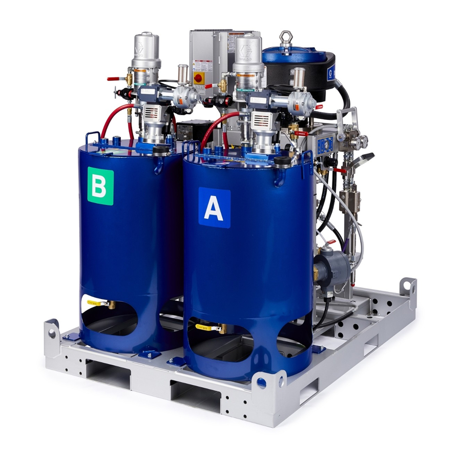
Page 15: Component Identification
Component Identification Component Identification XPs-hf Proportioners (Model 577101 shown) XP-hf Pump Assembly 3A6283F... - Page 16 Component Identification Key: XP-hf Motor Air Supply Hose Yoke with Rod Bearings Stand Recirculation Lines Main Air Controls, see page 18 Motor Position Indicator Bracket XP Displacement Pump Connecting Rod Nut Xtreme XL Air Motor Over-Pressure Rupture Disk; (for pumps that are 145cc or smaller) Primary Heaters BA Solvent Pump, see page 19 Solvent Pump Controls;...
-
Page 17: Junction Box
Component Identification Junction Box Key: MP Main Power Switch ZK Hose Heater Harness Entry Point ZA Power Indicator Light ZL Thermocouple Sensor Entry Point ZB Primary Heater Switches ZM Fluid Heater and Hopper Heater Harness Entry Point ZC Electrical Enclosure ZN Hopper Heater Switches ZE Hose Heater Switch ZR Electric Heated Hose Temperature Controller (Hazardous... -
Page 18: Fluid Control Assembly
Component Identification Fluid Control Assembly Shown with water-heated hose configuration Key: AA Recirculation Manifold AB Mix Manifold AC Recirculation Handle (shown closed), see page 21. AD Solvent Flush Valve AE Dual Shutoff Handle (shown closed) AF Fluid Pressure Gauges AH Fluid Recirculation Fittings AJ B Component Adjustable Fluid Restrictor;... -
Page 19: Solvent Pump
Component Identification Solvent Pump Pump Key: BA Solvent Pump BB Siphon Tube BE Solvent Prime Valve BF Solvent Supply Hose BG Solvent Prime Hose BH Solvent Pump Wet Cup Air Controls Key: DA Solvent Air Shutoff Valve (Relieving) DB Solvent Air Pressure Regulator DC Solvent Air Pressure Gauge DD Solvent Air Outlet DE Solvent Air Inlet... -
Page 20: Heated Hopper Assembly
Component Identification Heated Hopper Assembly Key: Double-Wall Hopper Heating Fluid Fill Port Hopper Lid Heating Fluid Vent Hopper Heater Air Valve (Feed Pump) Agitator Air Regulator (Feed Pump) Feed Pump Air Valve (Agitator) Y-Strainer Air Regulator (Agitator) Recirculation Tube Y-Strainer Valve Material Drain Fill Port Cap Heating Fluid Drain Valve... -
Page 21: System Components
System Components System Components Air Control Components Fluid Line Components Recirculation Manifold (AA) XP-hf Motor Air Valve (CA) Controls recirculation and pump priming. Mix Manifold (AB) Combines A and B fluid into one fluid line. Trapped air can cause the pump to cycle unexpectedly, which could result in serious injury from splashing or moving parts. -
Page 22: Heaters
System Components Heaters Pumps Primary Heaters (F) XP-hf Pump Assembly Viscon HF Fluid Heaters heat resin and hardener before A mechanically linked, fixed-ratio system that consists of the materials combine in the mix manifold assembly. a singular air motor and two individual XP displacement The heater improves chemical reaction and lowers pumps. -
Page 23: Setup
Setup Setup Initial System Setup Proper Lifting of Sprayer Follow these instructions to help prevent serious 1. Check the shipment for accuracy. Ensure you have injury or damage to equipment. Never lift while a received everything you ordered. See Component hopper is filled. -
Page 24: Grounding
Setup Grounding Air and fluid hoses: Use only electrically conductive hoses with a maximum of 300 ft (91 m) combined hose length to ensure grounding continuity. Check electrical resistance of hoses regularly. If total resistance to ground exceeds 29 megohms, replace hose immediately. The equipment must be grounded to reduce the risk Spray gun: Ground through connection to a properly of static sparking and electric shock. -
Page 25: Connect Power Source
Setup Connect Power Source NOTE: Required voltage and amperage is noted on the NOTE: The machine is provided with jumpers in the 380 control panel label. See Power Cord Guidelines tables Vac 3-Phase Wye position. below. NOTE: Terminal jumpers are not used for 480V. 4. - Page 26 Setup XPs-hf Wiring Diagram NON-HAZARDOUS LOCATIONS HAZARDOUS LOCATIONS Terminal Terminal Jumpers Disconnect Jumpers Disconnect ti37278a 230 Vac 230 Vac 380 Vac 480 Vac 1-Phase Delta 3-Phase Delta 3-Phase Wye 3-Phase Delta Disconnect Terminal Jumpers 3A6283F...
-
Page 27: Connect Explosion-Proof Heaters
Setup Connect Explosion-Proof Motor Position Heaters The motor position must be set for the volume mix ratio of the system. Hazardous location proportioners only NOTE: Changing the motor position does not change (xxx1x, xxxx3x) the mix ratio. Check Motor Position 1. - Page 28 Setup 4. Loosen the three nuts below the motor tie rods (P). 5. Slide the tie rods (P) and motor (E) until the indicator lines are aligned with your ratio. NOTICE Do not hit the tie rods (P) with a hammer. Damage to the air motor base may result.
-
Page 29: Connect Air Supply
Setup Connect Air Supply Connecting Heated Hose to Proportioner Connect the air supply hose to the main air inlet (AI). 1. Disconnect the solvent outlet hose (BF) and elbow Use a 1.0 in. (25.4 mm) ID minimum air hose. Do not fitting (BK) from the solvent flush valve (AD). -
Page 30: Connect Static Mixers, Gun, And Hoses
Setup Connect Static Mixers, Gun, and Add Heating Fluid to Heated Hoses Hoppers 1. Connect the outlet of the two primary static mixer tubes (AW) to the gun and hose assembly (ZU). 2. Check that all connections are tight. 1. Use a 50/50 mixture of water and ethylene glycol (engine coolant) for heating fluid in the outer cavity of the hopper. - Page 31 Setup 3. Use approximately 12 gallons (53 liters) to fill the 4. Replace the fill port cap (ET). cavity. Stop filling when fluid is visible at the bottom of the port elbow. NOTE: Thermal expansion may cause the heating fluid to overflow after it rises to temperature.
-
Page 32: Agitators (Ed)
Feed Pumps (EE) The Xtreme-Duty Agitator is provided with an airline ™ Fill the wet-cup half full with Graco Throat Seal (TSL lubricator to aid in proper maintenance. Fill the lubricator or a compatible solvent. with Air Motor Oil 202659 (do not fill past the maximum level shown in the oil fill sight glass). -
Page 33: Solvent Pump (Ba)
Solvent Pump (BA) Add Heating Fluid to Hoses (Water jacket heated hose packages only) Before starting, fill wet cup (BH) 1/3 full with Graco Throat Seal Liquid (TSL) or compatible solvent. 1. Add a 50/50 mixture of water and ethylene glycol to the reservoir (ZF) of the diaphragm pump (ZG). -
Page 34: Operation
Operation Operation Flush Before Using Equipment 3. Fill the “A” and “B” hoppers (J) with respective material, up to 25 gallons. Fill the “A” side (blue) with resin or base material. Fill the “B” side (green) The system was tested with lightweight oil, which is left with the hardener or catalyst. - Page 35 Operation 7. Fully open the feed pump air regulator (EN) and turn 12. Move the recirculation lines (U) back to the correct the feed pump air valve (EM) to OPEN. hopper. 8. Slowly open the feed pump air regulator (EN) to start the feed pump.
-
Page 36: Startup/Recirculate
Operation Startup/Recirculate 4. Slowly increase the agitator air regulator (ER) to turn the agitator until the desired speed is reached. 5. Ensure the feed pump air regulator (EN) is fully closed and open the feed pump air valve (EM) to the OPEN position. - Page 37 Operation 12. For systems with water-heated hose: Pump 13. For systems with water-heated hose only: setting - Set the flow rate of the heating fluid by Heater setting - Adjust the heater thermostat to the opening the diaphragm pump (ZG) needle valve desired temperature.
-
Page 38: Prime Solvent Pump
Operation Prime Solvent Pump 5. Open the solvent flush valve (AD) on the mix manifold. 1. Connect a ground wire (not included) to a metal pail of solvent. 2. Place the siphon tube (BB) and the solvent circulation hose (BG) in the pail of solvent. 6. - Page 39 Operation 8. Slowly turn the solvent pump air regulator (DB) 9. Close the solvent pump air valve (DA) and trigger clockwise to prime the solvent pump and push air the gun to relieve pressure. Engage the trigger lock out of the mix hose and gun. Continue to hold the (TL).
-
Page 40: Prime The Material Lines
Operation Prime the Material Lines (Units with heated hose and remote mix 5. Engage the trigger lock (TL). Remove the spray tip. manifold) TI1949a 1. Follow the Prime the Empty System procedure on ti1948a page 34. 6. Slowly increase the XP-hf motor air regulator (CB) enough to cycle the pumps. -
Page 41: Spray
Operation Spray 4. Slowly increase the XP-hf air regulator (CB) to cycle the pumps. 1. Follow the Startup/Recirculate procedure on page 2. Ensure that the XP-hf air pressure regulator (CB) and is fully closed and open the XP-hf air valve (CA). -
Page 42: Adjust The Restrictor
Operation Adjust the Restrictor 8. Adjust the XP-hf motor air regulator (CB) to the necessary spraying pressure and apply a coating to a test panel. The B side restrictor (AJ) reduces momentary “lead/lag” ratio imbalance of the A and B flow into the static mixer NOTE: Run System Verification tests everyday (see tubes (AN, AW) when the gun opens. -
Page 43: Pressure Relief Procedure
Operation Pressure Relief Procedure 4. Close the dual shutoff handle (AE). Follow the Pressure Relief Procedure whenever you see this symbol. This equipment stays pressurized until pressure is manually relieved. To help prevent serious injury from pressurized fluid, such as skin injection, splashing fluid 5. -
Page 44: Flushing
Operation Flushing Flush Mixed Material 1. Follow the Pressure Relief Procedure on page 43. 2. Ensure the solvent pump regulator (DB) is fully closed and open the solvent air valve (DA). To avoid fire and explosion, always ground equipment and waste container. To avoid static sparking and injury from splashing, always flush at the lowest possible pressure. - Page 45 Operation Flush Hoppers Procedure 5. Open the recirculation handle (AC). 1. Follow the Flush Mixed Material procedure on page 44. 2. Turn off all heater switches (ZB, ZE, ZN) and the main power switch (MP). Allow the system to cool before flushing.
- Page 46 Operation 8. Run the feed pumps until they are dry. Turn off the 10. Close the material drain (EH) and fill the hopper with feed pump air valve (EM) and agitator air valve solvent. (EP). 9. Place a small pail under the hopper and open the material drain (EH) to fully drain the spray material.
- Page 47 Operation Flush Material Lines Procedure 8. Close the main inlet air shutoff valve (CF). 1. Follow the Flush Mixed Material procedure on page 44. 2. Follow the Flush Hoppers Procedure on page 45. 3. Close the recirculation handle (AC) and open the dual shutoff handle (AE).
-
Page 48: Overnight Shutdown
Operation Overnight Shutdown 5. Turn off all heater switches (ZB, ZE, ZN) and the main power switch (MP). 1. Follow the Pressure Relief Procedure procedure on page 43. 2. Flush the mix manifold, hoses, and gun. Follow the Flush Mixed Material procedure on page 44. 3. -
Page 49: System Verification
System Verification Spots that take longer to cure indicate insufficient pump loading, leakage, or lead/lag errors at a remote mix manifold. Graco recommends running the following tests daily. Check for Normal Operation Appearance Test Every time you start spraying: Spray material onto foil. Look for variations in color, •... -
Page 50: Maintenance
Maintenance Maintenance Hose Electrical Resistance 3. Turn off all heaters and allow equipment to cool. 4. Flush mixed material. Follow the complete Flushing Check electrical resistance of hoses regularly. If total procedure starting on page 44. resistance to ground exceeds 29 megohms, replace hose immediately. -
Page 51: Clean Inlet Strainer Screen
Maintenance Clean Inlet Strainer Screen Check Heating Fluid Level Gradual fluid evaporation can occur. Check the level of heating fluid monthly. Add fluid as needed. NOTICE Freezing temperatures can cause damage that may The inlet strainers filter out particles that can plug the result in the heating fluid leaking into the terminal pump inlet check valves. -
Page 52: Feed Pumps
Maintenance Feed Pumps XP Displacement Pumps Check packing nut. Torque to 25-30 ft-lb (34-41 N•m). Keep the wet cup half filled with Graco Throat Seal ™ Liquid (TSL Keep the packing nut/wet-cup half filled with Graco Agitators ™ Throat Seal Liquid (TSL ) or compatible solvent to help prolong packing life. -
Page 53: Troubleshooting
Troubleshooting Troubleshooting 1. Follow Pressure Relief Procedure on page 43 before checking or repairing the system. 2. Check all possible problems and causes before disassembling the gun. Problem Cause Solution System stops or will not start. Air pressure or volume too low. Increase;... - Page 54 Troubleshooting Problem Cause Solution No pressure on hardener side; Overpressure rupture disk blown. Determine cause of fluid leaking from hardener pump overpressurization and correct. outlet rupture disk fitting. Replace rupture disk assembly 258962 (see page 15) and over pressure relief valve (302). Pressure and flow surges on Feed pressure too high.
-
Page 55: Pump Troubleshooting
Troubleshooting Pump Troubleshooting This chart uses proportioning fluid gauges to determine pump malfunctions. Observe the gauge readings during the stroke direction indicated by the bold arrow, and immediately after closing the gun or mix manifold. Refer to other manuals to troubleshoot individual components. TROUBLE AREA: TROUBLE AREA: Resin Pump Leakage... -
Page 56: Repair
Repair Repair Remove XP Displacement Pump 1. Flush all system components. Follow the complete Flushing procedure starting on page 44. 2. Disconnect the hopper fluid lines from the pump Follow the complete Flushing procedure starting on fluid inlet (228). page 44, which includes pressure relief and full system flushing if service time may exceed pot life time before 3. -
Page 57: Recirculation Manifold With Over Pressure Relief Valves
Repair Recirculation Manifold with Over Remove Motor Pressure Relief Valves 1. Flush all system components. Follow the complete Flushing procedure starting on page 44. 1. Flush all system components. Follow the complete 2. Disconnect the air line from the air motor. Flushing procedure starting on page 44. -
Page 58: Replace Over Pressure Relief Valves
Repair Replace Over Pressure Relief 5. Place a spring (720) over each valve stem. Place a clip (718) in each valve stem groove to retain the Valves springs. 1. Flush all system components. Follow the complete 6. Slide handle (711) onto valve stem and rotate Flushing procedure starting on page 44. - Page 59 Repair Material Recirculation Manifold Replacement Guide Colored Valve Sleeve ti19169a ti19168a Material Recirculation Manifold Replacement Table Circulation Relief Target Opening Manifold (35) Valve (302) Valve Sleeve Pressure Part Part Color psi (MPa, bar) Use with: 262783 262809 Gold 7100 (49, 490) All XPs50-hf models 262806 262520...
-
Page 60: Parts
Parts Parts XP50s-hf and XP70s-hf Proportioner Label No. 16F359 C Modifying this machine or adding La modificaci ó n de esta máquina o adici ó n de Modification de cette machine ou de l ajout Non-approved accessories voids the accesorios no autorizados anula la zona d accessoires non approuvés par les vides de Hazardous Area Approvals. -
Page 61: Xp50S-Hf And Xp70S-Hf Proportioners (Continued)
Parts XP50s-hf and XP70s-hf Proportioners (Continued) 3A6283F... -
Page 62: Xp50S-Hf And Xp70S-Hf Proportioners (Continued)
Parts XP50s-hf and XP70s-hf Proportioners (Continued) 3A6283F... - Page 63 Parts XP50s-hf and XP70s-hf Proportioners Parts List Ref. Part Description Qty. Ref. Part Description Qty. 55 16F359 LABEL, warning, fire/exp 25N579 CART, painted, XPs, hazard 25N583 MODULE, air controls, filter - - - - - VALVE, safety (see page 79) (see page 72) 16F615 TOOL, wrench, Xtreme...
-
Page 64: Water Jacketed Heated Hose Packages
Parts Water Jacketed Heated Hose Packages 3A6283F... - Page 65 Parts Water Jacketed Heated Hose Packages Parts List Qty. 240V 480V Ref. Part Description Ordinary Hazardous Ordinary Hazardous Locations Locations Locations Locations XXXX01 XXXX11 XXXX21 XXXX31 17N599 HARNESS, B heater, non-hazardous 17N598 HARNESS, A heater, non-hazardous 116171 BUSHING, strain relief 26C580 JUNCTION BOX, 240V, non-hazardous 26C581...
-
Page 66: Non-Heated Hose Packages
Parts Non-Heated Hose Packages 3A6283F... - Page 67 Parts Non-Heated Hose Packages Parts List Qty. 240 V 480 V Ref. Part Description Ordinary Hazardous Ordinary Hazardous Locations Locations Locations Locations XXXX02 XXXX12 XXXX22 XXXX32 17N599 HARNESS, B heater, non-hazardous 17N598 HARNESS, A heater, non-hazardous 116171 BUSHING, strain relief 26C580 JUNCTION BOX, 240V, non-hazardous 26C581...
-
Page 68: Non-Hazardous Location Electric Heated Hose Packages
Parts Non-Hazardous Location Electric Heated Hose Packages 240V 480V 3A6283F... -
Page 69: Hazardous Location Electric Heated Hose Packages
Parts Hazardous Location Electric Heated Hose Packages 3A6283F... - Page 70 Parts Electric Heated Hose Packages Parts List Qty. 240 V 480 V Ref. Part Description Ordinary Hazardous Ordinary Hazardous Locations Locations Locations Locations XXXX03 XXXX13 XXXX23 XXXX33 17N599 HARNESS, B heater, non-hazardous 17N598 HARNESS, A heater, non-hazardous 116171 BUSHING, strain relief 26C899 JUNCTION BOX, 240V, non-hazardous 26C905...
-
Page 71: Air Control Filter 25N583 Parts
Parts Air Control Filter 25N583 Parts Parts List Ref. Part Description Qty. Ref. Part Description Qty. 127785 COUPLING, universal, 1 in. nptf 116648 FITTING, swivel, 1 in. m x f 16W586 CABLE, lanyard, whip check 17N485 FITTING, tee, 1 x 1 x 1 npt(f), cs, 113161 SCREW, flange, hex hd 2.2k 16P338 SCREW, mach, serrated hex... -
Page 72: Air Control Regulator 25N575 Parts
Parts Air Control Regulator 25N575 Parts Ref. Part Description Qty. Ref. Part Description Qty. 406 108638 FITTING, pipe, tee 402 119363 FITTING, swivel, pipe 407 100960 GAUGE, press air 403 113163 VALVE, ball, vented, 1.0 408 116648 FITTING, swivel, 1 in. m x f 404 17S719 FITTING, 1 in. -
Page 73: Solvent Pump 262392 Parts
Parts Solvent Pump 262392 Parts Torque to 50-55 ft-lb (68-75 N•m). Torque to 75-80 ft-lb (102-108 N•m). Torque to 50-60 ft-lb (68-81 N•m). Ref. Part Description Qty. Ref. Part Description Qty. LW050A LOWER, assy, 50 cc 24F079 MOTOR, air, 6 in., std, slvt only 15T337 RESERVOIR, tsl, 50 cc lwr 7 1/2 111799 SCREW, cap, hex hd motor (not shown) -
Page 74: Solvent Air Control 24F126 Parts
Parts Solvent Air Control 24F126 Parts Ref. Part Description Qty. - - - - - PANEL, air controls, slvt, painted 15T500 GAUGE, pressure, air, pl mnt, 1/8 15T536 REGULATOR, air, 3/8 npt 16F810 NUT, regulator, steel 114362 VALVE, ball, air 15T498 FITTING, 90, swvl, 5/32 t x 1/8 fnpt 113498... -
Page 75: Heater Block Remote Manifold Kit
Parts Heater Block Remote Manifold Kit (Water Jacketed Heated Hose Packages Only) Kit 24Z934 Apply thread sealant to all non-swiveling Supplied loose, not installed. pipe threads. Ref. Part Description Qty. 24F834 CARRIAGE, weldment, remote manifold 16T294 PLATE, heater transfer, PFP 2k 110837 SCREW, flange, hex 110996 NUT, hex, flange head 126692 FITTING, tube, NPT x tube... -
Page 76: Material Recirculation Manifold With Over Pressure Relief Valve
Parts Material Recirculation Manifold with Over Pressure Relief Valve Assembly 262783 (XP50s-hf); 262806 (XP70s-hf) 708* 709* r_258988_3a0420a_1c Apply anaerobic pipe sealant to all non-swiveling pipe Further tighten either valve (302) as required to line threads. up handle straight across. Torque to 28-32 ft-lb (38-43 N•m). Apply grease to spring ends. -
Page 77: Diaphragm Pump 273093 Parts
Parts Diaphragm Pump 273093 Parts (Water Jacketed Heated Hose Packages Only) Apply thread sealant to all non-swiveling pipe threads. Orient fittings approximately 15 degrees away from pump. Orient fittings as shown. Install ground wire between screw and washer. The nut is held in the slot of the pump. Install two loose plugs and muffler provided with pump in the ports indicated. -
Page 78: Xp-Hf Pump Assembly Parts
Parts XP-hf Pump Assembly Parts Torque to 50-60 ft-lb (68-81 N•m). Torque together to 230-250 ft-lb (312-339 N•m). Torque to 145-155 ft-lb (196-210 N•m). Torque together to 95-105 ft-lb (129-142 N•m). Apply medium strength (blue) threadlock to top thread only. Pins and lanyards must be positioned toward the outside of the pump as shown. - Page 79 Parts XP-hf Pump Assembly Parts List Ref. Part Description Qty. Ref. Part Description Qty. 921a 16P338 SCREW, mach, serrated hex hd 273087 PLATE, XP-hf, motor 921b 17N312 PLATE, XP-hf, finger guard 273086 ROD, tie, 4 in. long, 1 in. dia 273092 COVER, pump 273088 MOTOR, air, 13 in.
-
Page 80: Recommended Spare Parts
Recommended Spare Parts Recommended Spare Parts Keep these spare parts on hand to reduce downtime. 1/2 in. Mix Manifold Inlet Ball Valves 24M601, Ball valve repair kit Pump Repair Kits 262740, Spare valve (no handle) 262739, Spare valve (single handle) See Models (page 10) to see what pumps are used on your system. -
Page 81: Accessories And Kits
Accessories and Kits Accessories and Kits Remote Mix Manifold Carriage, 262522 ™ PressureTrak Kit, 25C452 A protective guard to mount mix manifold remote. See Monitors pressures to provide ratio assurance on XP-hf mix manifold manual 3A0590 for more information. plural component sprayers in hazardous and non-hazardous locations. -
Page 82: Dimensions
Dimensions Dimensions System Dimensions Top View Side View 3A6283F... -
Page 83: Technical Specifications
Technical Specifications Technical Specifications XPs-hf System U.S. Metric Output Maximum Fluid Working Pressure See Models section beginning on page 10. Combined Fluid Output (cc/cycle) See Models section beginning on page 10. Pressure Ratio See Models section beginning on page 10. Fluid Flow at 20 cpm See Models section beginning on page 10. - Page 84 Technical Specifications XXXX31 1475 lb 700 kg XXXX32 1425 lb 646 kg XXXX33 1450 lb 658 kg Sound Data Sound Power measured at 70 psi Greater than 96 dBA (0.48 MPa, 4.8 bar), 20 cpm, per ISO-9614-2 Sound Pressure tested at Greater than 86.8 dBA 3.28 ft (1 m) from equipment Proportioner...
-
Page 85: Recycling And Disposal
Technical Specifications Xtreme Duty Agitator U.S. Metric Input Maximum air input 100 psi 6.7 bar, 0.67 MPa Air inlet size 3/8 in. npsm Air Consumption 30 rpm at 20 psi (1.4 bar, 0.14 MPa) 7 cfm 0.198 m3/min 60 rpm at 80 psi (5.5 bar, 0.55 MPa) 30 cfm 0.850 m3/min Maximum free speed at 100 psi (6.7 bar, 0.67 MPa) -
Page 86: Graco Standard Warranty
With the exception of any special, extended, or limited warranty published by Graco, Graco will, for a period of twelve months from the date of sale, repair or replace any part of the equipment determined by Graco to be defective.
Need help?
Do you have a question about the XPs-hf Series and is the answer not in the manual?
Questions and answers