Extra 300LT Maintenance Manual
Electronic toys
Hide thumbs
Also See for 300LT:
- Information manual (264 pages) ,
- Maintenance manual (31 pages) ,
- Maintenance manual (551 pages)

Related Manuals for Extra 300LT


Summary of Contents for Extra 300LT
- Page 1 MAINTENANCE MANUAL EXTRA 300LT Doc. No: EA-0D702 EXTRA FLUGZEUGPRODUKTIONS- UND VERTRIEBS-GMBH Schwarze Heide 21 D-46569 Hünxe, Germany Tel: 49-28 58-91 37-0 Fax: 49-28 58-91 37-30...
-
Page 2: Log Of Revisions
MAINTENANCE MANUAL EXTRA 300LT Log of Revisions Dates of issue for original and revised pages: Date and sign of approval: 1st Edition (Chapter 4 & 5 only) ..... 30. April 2010 EASA MAJOR CHANGE APPROVAL N° 10030180 ..........1. June 2010... - Page 3 MAINTENANCE MANUAL EXTRA 300LT Log of Effective Pages Chapter Page Date of Issue Chapter Page Date of Issue Chapter Page Date of Issue Cover sheet 7. July 2010 7. July 2010 7. July 2010 7. July 2010 7. July 2010 7.
- Page 4 MAINTENANCE MANUAL EXTRA 300LT Log of Effective Pages Chapter Page Date of Issue Chapter Page Date of Issue Chapter Page Date of Issue 7. July 2010 7. July 2010 7. July 2010 7. July 2010 7. July 2010 7. July 2010 7.
- Page 5 MAINTENANCE MANUAL EXTRA 300LT Log of Effective Pages Chapter Page Date of Issue Chapter Page Date of Issue Chapter Page Date of Issue 7. July 2010 7. July 2010 7. July 2010 7. July 2010 7. July 2010 7. July 2010 7.
-
Page 6: List Of Service Bulletins/Service Letters
MAINTENANCE MANUAL EXTRA 300LT List of Service Bulletins/Service Letters Issue Serial N° German AD S.B./S.L. N° Subject Date affected (LTA) PAGE DATE: 7. July 2010 PAGE E... -
Page 7: Table Of Contents
MAINTENANCE MANUAL EXTRA 300LT CONTENTS Title Page Log of Revisions .................................... - Page 8 CONTENTS MAINTENANCE MANUAL EXTRA 300LT STRUCTURES Standard Practices and Structures - General ......................
- Page 9 From: ............. Date: .............. Address: ..........................................................Tel. N°: ............Fax N°: ............To: EXTRA-Flugzeugproduktions- und Fax N°: ......(49)-2858-913730 Vertriebs GmbH Aircraft Description: Type: ......Serial No: ....Flight hours: ....Landings: ....Detailed Description of Damage or Problem...
- Page 10 MAINTENANCE MANUAL EXTRA 300LT Chapter 1 Introduction PAGE DATE: 7. July 2010 CHAPTER PAGE...
- Page 11 MAINTENANCE MANUAL EXTRA 300LT Table of Contents Chapter Title 01-00-00 GENERAL ........3 01-00-01 Trade Marks .
- Page 12 According to the regulations of the FAR part 23, this maintenance manual provides educated maintenance staff with information necessary for servicing, maintaining and repairing the EXTRA 300LT. This manual contains a detailed description of systems including time limits for the particu- lar components, troubleshooting and instructions for the performance of inspection and maintenance work.
- Page 13 GENERAL MAINTENANCE MANUAL EXTRA 300LT Engine: Lycoming AEIO-580-B1A Operaton and Installation Manual AEIO-580 • (P/N:60297-32) Maintenance and Overhaul Man. AEIO-580 • (P/N: LMO-AEIO-580) Service Letters, Bulletins and Instructions INDEX • Service Letters, Bulletins and Instructions • Manufacturer: LYCOMING ENGINES 652 Oliver Street,...
- Page 14 GENERAL MAINTENANCE MANUAL EXTRA 300LT Magneto Start Booster: SlickSTART SS1001 Operation, Maintenance and • Troubleshooting Manual L-1492 Service Bulletins • Manufacturer: UNISON INDUSTRIES 530 Blackhawk Part Avenue Rockford, IL 61104 , USA Inverted Oil System: CHRISTEN 801 Series (mod.) Product Manual (P/N: 70047-001) •...
- Page 15 MAINTENANCE MANUAL EXTRA 300LT Artex ME406 ELT Description, Operation, Installation and Maintenance • Manual ME406 and ME406HM ELT (P/N: 570-1600) Manufacturer: Artex Aircraft Supplies P.O. Box 1270 Canby, Oregon 97013 Aspen EFD1000/500 System Installation Manual #900-00003-001(Rev. G) • ICA Document #900-00012-001(Rev. D) •...
- Page 16 MAINTENANCE MANUAL EXTRA 300LT 01-10-00 SAFETY To keep the security risks during the execution of the inspection and maintenance work as low as possible, observe the following points: Inspection and maintenance work has to be carried out only • by qualified and authorized personnel.
-
Page 17: How To Use The Service Manual
MAINTENANCE MANUAL EXTRA 300LT Chapter 2 How to Use the Service Manual PAGE DATE: 7. July 2010 CHAPTER PAGE... - Page 18 MAINTENANCE MANUAL EXTRA 300LT Table of Contents Chapter/Figure Title 02-10-00 MANUAL DESCRIPTION ..... 3 02-10-01 Manual Set-Up ....... . 3 02-10-02 Chapter Set-Up .
-
Page 19: Manual Description
MAINTENANCE MANUAL EXTRA 300LT 02-00-00 GENERAL The set-up of the manual, the chapters and the handling correspond to the regulations of the Air Transport Associa- tion of America, ATA Specification No. 100. Only the num- bering of the pages and the layout have been changed to make working with this manual easier. -
Page 20: Page Numbering
MAINTENANCE MANUAL EXTRA 300LT defined by the manufacturer. If a more detailed breakdown is necessary, bold faced headlines like the following are used: Powerplant 02-10-03 Page Numbering The page numbering begins at the coversheet of each chapter with "Page 1". In contrast to the ATA Specification 100, the particular sections and subjects don't start with a new numbering. -
Page 21: Layout
MAINTENANCE MANUAL EXTRA 300LT 02-10-05 Layout Apart from the headers and footers the layout consists of two columns. The right column contains text, titles, tables, schedules and figures (figures also can fill the whole page); the left column contains the chapter numbering, boxed textmarkers for notes and safety notes as well as explana- tions. -
Page 22: Notes/Safety Notes
MAINTENANCE MANUAL EXTRA 300LT 02-10-06 Notes/Safety Notes Safety notes in this manual are marked by a boxed textmarker in the margin column and written in semi-bold characters. This manual distinguishes three warning levels: D A N G E R Represents a threatening danger for the personnel. The non-observation of this safety note will result in death or serious injuries. -
Page 23: Handling
Cross-check your documents against these publications and replace pages as necessary. Paper copies of publications will continue to be available if this is your preferred format of publications. Orders can be placed by contacting Extra Aircraft at e-mail: ExtraAircraft@ExtraAircraft.com or facsimile: +49-(0) 2858-9137-30. -
Page 24: Service Bulletin
MAINTENANCE MANUAL EXTRA 300LT 02-20-02 Service Bulletin The service bulletins describe which procedures and how and when they are to be carried out. Enter the receipt of each service bulletin in the Service Bulletin List (page E). Service Bulletins are also available under the Web-link given in section 02-20-01. -
Page 25: Fax-Formats
MAINTENANCE MANUAL EXTRA 300LT 02-20-04 Fax-Formats When contacting EXTRA-Flugzeugproduktions- und Vertriebs-GmbH is advisable in case of questions and/or problems during maintenance of aircraft copy and use the fax-format you find on the preceding pages ("H") for correct identification of aircraft, equipment and existing technical instructions. -
Page 26: General Description
MAINTENANCE MANUAL EXTRA 300LT Chapter 3 General Description PAGE DATE: 7. July 2010 CHAPTER PAGE... - Page 27 GENERAL ........3 Figure 1 View EXTRA 300LT ......3 03-10-00 DESCRIPTION .
-
Page 28: General
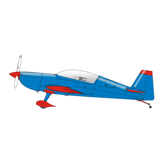
A more detailed description of the systems you find in the respective chapters (see: CONTENTS). The Extra 300LT (refer to figure 1) is designed as a light weight, single-engine, two seat, low-wing monoplane using composite and steel materials. It has a fixed main landing gear and a tail wheel unit with full-swivel capability. -
Page 29: Description
MAINTENANCE MANUAL EXTRA 300LT 03-10-00 DESCRIPTION 03-10-01 Construction Manufacturer: EXTRA-Flugzeugproduktions- und Vertriebs- GmbH Flugplatz Dinslaken D-46569 Hünxe, Germany Fuselage: steel tube design, covered with fabric, composite material resp. aluminium sheet metal, single piece canopy side hinged Wing: fibre composite design... -
Page 30: Brake System
MAINTENANCE MANUAL EXTRA 300LT 03-10-03 Brake System Main wheels: hydraulically operated disc brakes, hydraulic cylinders actuated by brake pedals Tail wheel: no brake 03-10-04 Powerplant Engine Manufacturer: TEXTRON LYCOMING Williamsport Division 652 Oliver Street Williamsport Plant 17 701 Type: AEIO - 580-B1A (6 cyl. -
Page 31: Fuel System
MAINTENANCE MANUAL EXTRA 300LT 03-10-05 Fuel System Tanks: 2 integral wing tanks, 1 center and 1 acro tank behind the firewall (cockpit side) Fuel supply: mechanical engine driven pump, additional electrically operated boost pump 03-10-06 Electrical system Power supply: engine driven 12 V alternator,... -
Page 32: Instruments
MAINTENANCE MANUAL EXTRA 300LT 03-10-07 Instruments Standard (minimum) equipment installed (X): PAGE DATE: 7. July 2010 CHAPTER PAGE... -
Page 33: Airworthiness Limitations
MAINTENANCE MANUAL EXTRA 300LT Chapter 4 Airworthiness Limitations PAGE DATE: 30. April 2010 CHAPTER PAGE... - Page 34 MAINTENANCE MANUAL EXTRA 300LT Log of Revisions Chapter 4 Dates of issue for original and revised pages: Date and sign of approval: 1st Edition ..........30. April 2010 EASA MAJOR CHANGE APPROVAL N° 10030180 ..........1. June 2010 PAGE DATE: 30. April 2010...
- Page 35 MAINTENANCE MANUAL EXTRA 300LT Table of Contents Chapter Title 04-00-00 GENERAL ........4 04-00-01 Temperature Limit .
-
Page 36: General
MAINTENANCE MANUAL EXTRA 300LT 04-00-00 GENERAL For each inspection listed here, refer to the applicable chapter in this manual. I M P O R T A N T It is the operator's responsibility to make sure that time limits or life limits for items in this chapter are not exceeded. - Page 37 GENERAL Operating Time MAINTENANCE MANUAL EXTRA 300LT The reliability of the composite primary parts has been convincingly demonstrated by fatique testing (Two times design life 2x6000 = 12000 hrs). I M P O R T A N T Every 1000 flight hours the "Significant Items Inspec- tion"...
-
Page 38: Life Limited Components
6000 h 04-10-03 Service Life Limited Components The service life of the EA 300LT composite structure as listed in section 04-10-02 has been set to 6000 flight hours. A "Major Inspection" on reaching 6000 flight hours may provide the necessary clearance for further flight. This "Major Inspection"... -
Page 39: Major Inspection
MAINTENANCE MANUAL EXTRA 300LT 04-20-00 MAJOR INSPECTION The EXTRA 300LT has been manufactured utilizing the latest knowledge of composite construction and requires new experience about those parts subject to wear. Until now insufficient experience about this point has been acquired. -
Page 40: Time Limits/Maintenance Checks
MAINTENANCE MANUAL EXTRA 300LT Chapter 5 Time Limits/Maintenance Checks PAGE DATE: 7. July 2010 CHAPTER PAGE... - Page 41 MAINTENANCE MANUAL EXTRA 300LT Table of Contents Chapter/Figure Title 05-00-00 GENERAL ........3 05-10-00 TIME LIMIT COMPONENTS .
-
Page 42: General
EXTRA 300LT. The periodic inspections and checks de- scribed and their recommended time intervals are minimum requirements for maintaining the aircraft in an airworthy condition. -
Page 43: Time Limit Components
MAINTENANCE MANUAL EXTRA 300LT 05-10-00 TIME LIMIT COMPONENTS 05-10-01 General All components not listed herein should be inspected as detailed in Chapter 05-20 „Maintenance Checks“ and re- paired, overhauled as required. It is recommended that overhaul or replacement of components should be accom-... -
Page 44: Recommended Replacement Times
TIME LIMIT COMPONENTS MAINTENANCE MANUAL EXTRA 300LT 05-10-03 Recommended Replacement Times It is recommended to replace the items shown in the following schedule at the times indicated. The times may be modified by the respective national authorities. * on the recommendation... -
Page 45: Time Between Inspection
MAINTENANCE MANUAL EXTRA 300LT 05-10-04 Time Between Inspection Inspect these equipment items at the times shown: PAGE DATE: 7. July 2010 CHAPTER PAGE... -
Page 46: Scheduled Maintenance Checks
MAINTENANCE MANUAL EXTRA 300LT 05-20-00 SCHEDULED MAINTENANCE CHECKS 05-20-01 General Scheduled maintenance checks or tasks must be carried out at 25, 50, 100, 200, 300, 400, 500 and 1000 hour intervals. In addition an annual inspection equal to the 100 hour inspection has to be performed. -
Page 47: Drain And Vent Holes
SCHEDULED MAINTENANCE CHECKS MAINTENANCE MANUAL EXTRA 300LT Figure 1 Drain and Vent Holes PAGE DATE: 7. July 2010 CHAPTER PAGE... -
Page 48: Lubrication Chart 25 Hours
SCHEDULED MAINTENANCE CHECKS MAINTENANCE MANUAL EXTRA 300LT Figure 2 Lubrication Chart 25 hours PAGE DATE: 7. July 2010 CHAPTER PAGE... -
Page 49: Lubrication Chart 50 Hours
SCHEDULED MAINTENANCE CHECKS MAINTENANCE MANUAL EXTRA 300LT Figure 3 Lubrication Chart 50 hours PAGE DATE: 7. July 2010 CHAPTER PAGE... -
Page 50: Lubrication Chart 100 Hours
SCHEDULED MAINTENANCE CHECKS MAINTENANCE MANUAL EXTRA 300LT Figure 4 Lubrication Chart 100 hours PAGE DATE: 7. July 2010 CHAPTER PAGE... -
Page 51: Maintenance Checks Schedule
SCHEDULED MAINTENANCE CHECKS MAINTENANCE MANUAL EXTRA 300LT 05-20-04 Maintenance Checks Schedule The maintenance checks described in this chapter include all the scheduled checks which must be performed. Use the following schedule and the lubrication charts (figures 2-4). Date: Inspector: Mechanic: Serial No.:... - Page 52 Serial No.: Inspections O O 17 Check optional electronic g-meter for the maximum g- loading. If extreme value exceeds ±10 G, contact EXTRA- Flugzeug-produktions- und Vertriebs- GmbH. O O 18 Ignition OFF, main switch OFF, remove ignition key. O O 19 Check if ignition key is removable in OFF-position only, and if key functions in accordance with the requirements of the Teledyne Continental Service Bulletin No.
- Page 53 SCHEDULED MAINTENANCE CHECKS Maintenance Checks Schedule MAINTENANCE MANUAL EXTRA 300LT Date: Inspector: Mechanic: Serial No.: Inspections Engine compartment (Refer to latest edition of Textron Lycoming Operator´s and Maintenance Manual and SB's, Christen Product Manual 801 Series and SB's, Slick Magneto Maintenance and Over- haul Manual and SB's.
- Page 54 SCHEDULED MAINTENANCE CHECKS Maintenance Checks Schedule MAINTENANCE MANUAL EXTRA 300LT Date: Inspector: Mechanic: Serial No.: Inspections 15 Clean and flush the Inverted Oil System with a suitable petroleum solvent, such as Varsol according to Lycoming Operator’s and Maintenance Manual. O O 16 Service engine with recommended lubricating oil in accord- ance with chapter 12-10-04.
- Page 55 SCHEDULED MAINTENANCE CHECKS Maintenance Checks Schedule MAINTENANCE MANUAL EXTRA 300LT Date: Inspector: Mechanic: Serial No.: Inspections 26 Overhaul or replace magnetos. O 27 Adjust magneto to engine timing, refer to Slick Magneto Maintenance and Overhaul Manual O 28 Inspect magneto wiring connections, vent holes and P-lead attachment, refer to Slick Magneto Maintenance and Over- haul Manual.
- Page 56 SCHEDULED MAINTENANCE CHECKS Maintenance Checks Schedule MAINTENANCE MANUAL EXTRA 300LT Date: Inspector: Mechanic: Serial No.: Inspections O 40 Inspect all external exhaust surfaces for signs of leakage. O 41 Inspect all external exhaust joints, slip joints, clamps, couplings for misalignment, warpage, broken, loose or missing fasteners, clamps, gaskets or seals and abnormal wear.
- Page 57 SCHEDULED MAINTENANCE CHECKS Maintenance Checks Schedule MAINTENANCE MANUAL EXTRA 300LT Date: Inspector: Mechanic: Serial No.: Inspections O 56 Inspect condition and tension of alternator drive belt O 57 Inspect security of alternator mounting O 58 Inspect starter and starter drive O O 59 Clean engine if necessary.
- Page 58 9 Visually inspect steel tube construction in the area of hori- zontal stabilizer attach brackets for cracks. In case of doubt remove horizontal stabilizer and use a dye check penetrant. In case cracks are found contact EXTRA- Flugzeugproduktions- und Vertriebs- GmbH for repair advice.
-
Page 59: Flight Controls
SCHEDULED MAINTENANCE CHECKS Maintenance Checks Schedule MAINTENANCE MANUAL EXTRA 300LT Date: Inspector: Mechanic: Serial No.: Inspections Fuel system O O 22 Inspect the fuel lines for leaks, security, chafing, dents and cracks. Replace fuel lines as required. O O 23 Inspect fuel selector valve for operation and proper pointer indication. - Page 60 If the stop is reached the control system indicates too much flexibility which needs to be traced. In this case contact EXTRA Flugzeugproduktions- und Vertriebs- GmbH for advice. O O 14 Inspect all flight control surface ventilation holes for obstruction.
-
Page 61: Landing Gear
SCHEDULED MAINTENANCE CHECKS Maintenance Checks Schedule MAINTENANCE MANUAL EXTRA 300LT Date: Inspector: Mechanic: Serial No.: Inspections Landing gear 1 Check landing gear for general condition. 2 Visually inspect main landing gear spring for dents and cracks. 3 Visually inspect main landing gear spring for deformations, especially in the area of the mounting clamps. - Page 62 SCHEDULED MAINTENANCE CHECKS Maintenance Checks Schedule MAINTENANCE MANUAL EXTRA 300LT Date: Inspector: Mechanic: Serial No.: Inspections O O 13 Inspect the brake disc for rust, excessive grooves, large cracks, coning or other visible damage. Check if disc thick- ness is more than 0.325in/8.255mm. Coning of disc in excess of 0.015 in /0.381 mm is cause for replacement.
- Page 63 MAINTENANCE MANUAL EXTRA 300LT Date: Inspector: Mechanic: Serial No.: Inspections Brake system O O 21 Inspect brake assemblies for general condition. O O 22 Inspect master cylinders for leaks. O 23 Inspect brake lines for leaks, bulges and deterioration. Inspect brake lines for kinks, especially in the extreme positions of pedals.
- Page 64 MAINTENANCE MANUAL EXTRA 300LT Date: Inspector: Mechanic: Serial No.: Inspections O O 34 Check tail wheel rubber tire condition. O O 35 Inspect tail wheel fork and swivel arm mounting bolt for security. O O 36 Check the connector springs for light precompression.
- Page 65 MAINTENANCE MANUAL EXTRA 300LT Date: Inspector: Mechanic: Serial No.: Inspections Instruments 1 Inspect panel mounting for security and safety. 2 Check operation, mounting, and wiring of switches for condition and safety. 3 Check automatic circuit breaker mounting and wiring for condition and safety.
- Page 66 4 Check landing light for function. 5 Aircraft conforms to specifications of respective authority 6 All required airworthiness directives complied with. 7 All EXTRA mandatory Service Bulletins complied with. 8 All vendor Service Bulletins and Service Letters complied with. 9 Check for proper flight manual.
-
Page 67: Significant Items Inspection
SCHEDULED MAINTENANCE CHECKS MAINTENANCE MANUAL EXTRA 300LT 05-20-05 Significant Items Inspection Every 1000 flight hours the "Significant Items Inspection" must be performed in addition to the 100-hour inspection. Inspector: Date: Mechanic: Serial No.: Inspections Wing O 1 Remove wing as per chapter 57. - Page 68 SCHEDULED MAINTENANCE CHECKS Significant Items Inspection MAINTENANCE MANUAL EXTRA 300LT Inspector: Date: Mechanic: Serial No.: Inspections O 13 Inspect aileron cantilever bearings for play. Check for free move- ment and cleanliness. O 14 Inspect attachment fitting for cracks, damage and corrosion. Check for link bolts security.
- Page 69 SCHEDULED MAINTENANCE CHECKS Significant Items Inspection MAINTENANCE MANUAL EXTRA 300LT Inspector: Date: Mechanic: Serial No.: Inspections O 5 Inspect spades visually for general condition. Check spade support for corrosion, cracks and deformations. Ensure proper attachment to aileron. O 6 Inspect ventilation holes for obstruction.
- Page 70 SCHEDULED MAINTENANCE CHECKS Significant Items Inspection MAINTENANCE MANUAL EXTRA 300LT Inspector: Date: Mechanic: Serial No.: Inspections Rudder O 1 Remove rudder as per chapter 27. O 2 Inspect tip area bonding to the skin laminate by coin tapping. O 3 Inspect skin to lower horn rib bonding for delaminations by coin tapping and for cracks.
- Page 71 SCHEDULED MAINTENANCE CHECKS Significant Items Inspection MAINTENANCE MANUAL EXTRA 300LT Inspector: Date: Mechanic: Serial No.: Inspections O 6 Inspect elevator cantilever bearings for play. Check for free move- ment and cleanliness. O 7 Inspect central attachment fitting for cracks, damage and corrosion.
- Page 72 SCHEDULED MAINTENANCE CHECKS Significant Items Inspection MAINTENANCE MANUAL EXTRA 300LT Inspector: Date: Mechanic: Serial No.: Inspections Surface general O 11 Check paint for general condition (blisters etc.). O 12 Check laminate for erosion, scratches, stone nicks and impact damages. O 13 Reinstall elevator actuator lever.
- Page 73 SCHEDULED MAINTENANCE CHECKS Significant Items Inspection MAINTENANCE MANUAL EXTRA 300LT Inspector: Date: Mechanic: Serial No.: Inspections O 8 Detailed visual inspection of control cables and PTFE-coating. O 9 Check condition, attachment and function of trim servo. O 10 Detailed visual inspection of trim tab actuator levers for damages and cracks.
- Page 74 MAINTENANCE MANUAL EXTRA 300LT Inspector: Date: Mechanic: Serial No.: Inspections Tail-wheel landing gear O 1 Inspect glass fibre spring visually for dents, cracks and delaminations. O 2 Inspect mounting bolts and nuts for fretting, wear, damage, stretch and proper torque.
- Page 75 SCHEDULED MAINTENANCE CHECKS Significant Items Inspection MAINTENANCE MANUAL EXTRA 300LT Inspector: Date: Mechanic: Serial No.: Inspections Hardware O 1 Check harness attachment fittings for cracks, deformations and corrosion. O 2 Check bolts and nuts in critical areas for fretting, wear, damage, stretch, proper torque and safety.
-
Page 76: Unscheduled Maintenance Checks
MAINTENANCE MANUAL EXTRA 300LT 05-50-00 UNSCHEDULED MAINTENANCE CHECKS Unscheduled checks are only performed following abnormal events, which could possibly have caused damage to the aircraft or impaired the airworthiness. I M P O R T A N T In case of abnormal events or any exceedance of given limitations (load factor, never exceed speed, etc.) the... - Page 77 UNSCHEDULED MAINTENANCE CHECKS Hard Landing MAINTENANCE MANUAL EXTRA 300LT Inspector: Date: Mechanic: Serial No.: Inspections Landing gear O 1 Examine landing gear mounting clamps for defects (e.g. cracks and deformed areas). O 2 Check clamp bolts and anti abrasion strips of the landing gear for cracks and wear, replace when necessary.
-
Page 78: Engine Fire
UNSCHEDULED MAINTENANCE CHECKS MAINTENANCE MANUAL EXTRA 300LT 05-50-03 Engine Fire After an engine fire, perform a check as described in the following: For damage evaluation consult the manufacturer, before the aircraft is put back into service. Date: Inspector: Mechanic: Serial No.: Inspections O 1 Check all cables and hoses, replace when necessary. -
Page 79: Flightline Inspections
UNSCHEDULED MAINTENANCE CHECKS MAINTENANCE MANUAL EXTRA 300LT 05-50-05 Flightline Inspections These checks include pre-flight and postflight checks, as they are described in Sections 3 and 4 ("EMERGENCY PROCEDURES" and "NORMAL PROCEDURES") of the PILOT´S OPERATING HANDBOOK. When the aircraft is in operation, perform these checks daily. -
Page 80: Dimensions And Areas
MAINTENANCE MANUAL EXTRA 300LT Chapter 6 Dimensions and Areas PAGE DATE: 7. July 2010 CHAPTER PAGE... - Page 81 Rudder ........5 Figure 2 Three-View EXTRA 300LT ..... . 6 PAGE DATE: 7. July 2010...
-
Page 82: General
MAINTENANCE MANUAL EXTRA 300LT 06-00-00 GENERAL The for measuring and weighing the aircraft relevant refer- ence planes are the following: Reference Planes Plane of upper longerons (horizontal plane) Plane of rudder (Vertical/symmetry plane) Fire wall plane (Vertical plane) The following figure1shows the aircraft reference planes:... -
Page 83: Main Data
MAINTENANCE MANUAL EXTRA 300LT 06-10-00 MAIN DATA 06-10-01 Main Dimensions (Refer to figure 2 on page 6) Length: 7.01 m (23.00 ft) Height 1: 2.62 m (8.60 ft) Height 1 Height 2 : 2.59 m (8.45 ft) Height 2 Span: 8.00 m (26.25 ft) -
Page 84: Horizontal Tail
MAIN DATA MAINTENANCE MANUAL EXTRA 300LT 06-10-03 Horizontal Tail Span: 3.20 m (10.50 ft) Area: 2.55 m² (27.45 ft²) Airfoil: Wortmann FX 71-L-150/30 06-10-04 Elevator Area: 0.772 m² (7.77 ft²) Elevator-deflection: up 25°, tolerance ± 2° down 25°, tolerance - 2°... -
Page 85: Three-View Extra 300Lt
MAIN DATA MAINTENANCE MANUAL EXTRA 300LT Figure 2 Three-View EXTRA 300LT PAGE DATE: 7. July 2010 CHAPTER PAGE... -
Page 86: Lifting And Shoring
MAINTENANCE MANUAL EXTRA 300LT Chapter 7 Lifting and Shoring PAGE DATE: 7. July 2010 CHAPTER PAGE... - Page 87 MAINTENANCE MANUAL EXTRA 300LT Table of Contents Chapter/Figure Title 07-10-00 JACKING ........3 07-10-01 Balance Weight .
-
Page 88: Jacking
MAINTENANCE MANUAL EXTRA 300LT 07-10-00 JACKING 07-10-01 Balance Weight Prior to the removal of the horizontal and/or vertical stabilizer(s) or prior to shoring the aircraft as described in chapter 07-20-00 it is necessary to weight the tail to prevent aircraft from tilting onto the nose. In this case follow the steps described below (refer to figure 1): 1 Put a weight (1) of min. -
Page 89: Shoring
MAINTENANCE MANUAL EXTRA 300LT 07-20-00 SHORING Shoring the Extra 300LT is necessary, when the main landing gear or the tail wheel has to be removed or installed. 07-20-01 Shoring the Front 1 Remove the engine cowlings as per chapter 71 and the bottom fuselage cover incl. -
Page 90: Shoring The Tail
MAINTENANCE MANUAL EXTRA 300LT 07-20-02 Shoring the Tail Refer to figure 3. Secure the main wheels with wheel chocks. Make available two approx. 2.5 feet high, approx. 1 foot wide and approx. 3 feet long supports. Cushion the supports. C A U T I O N Don´t handle the elevator when lifting the tail. - Page 91 MAINTENANCE MANUAL EXTRA 300LT Chapter 8 Leveling and Weighing PAGE DATE: 7. July 2010 CHAPTER PAGE...
- Page 92 MAINTENANCE MANUAL EXTRA 300LT Table of Contents Chapter/Figure Title 08-00-00 GENERAL ........3...
- Page 93 08-00-00 GENERAL This chapter contains all information and procedures that are necessary for weighing and leveling the EXTRA 300LT and for determining the Center of Gravity. Weigh the aircraft and determine the Center of Gravity each 5 years, after installation of additional equipment or after repairs.
- Page 94 MAINTENANCE MANUAL EXTRA 300LT 08-10-00 WEIGHING AND CALCULATION OF C OF G N O T E Weigh the aircraft only on even floor and in closed shops (wind protected). Use three identical scales. Ensure that the aircraft is fully equipped with equipment in locations according to the equipment list (Pilot´s Operating...
- Page 95 WEIGHING MAINTENANCE MANUAL EXTRA 300LT Gross weight scale 1 ..kg Tare weight scale 1 (chocks) – ..kg Net weight scale 1 (W ..kg Gross weight scale 2 .
- Page 96 WEIGHING MAINTENANCE MANUAL EXTRA 300LT Empty Weight and Center of Gravity Position EXTRA 300LT Data according to "TC Data-Sheet" and "Pilot´s Operating Handbook and EASA approved Airplane Flight Manual" Doc.-No.: EA - 0D701 Equipment according to Equipment List dated: ... .
- Page 97 MAINTENANCE MANUAL EXTRA 300LT 08-20-00 LEVELING N O T E Level the aircraft only on even floor and in closed shops (wind protected). Secure each main wheel with two wheel chocks. W A R N I N G Do not lift tail wheel higher than necessary for leveling.
-
Page 98: Towing And Taxiing
MAINTENANCE MANUAL EXTRA 300LT Chapter 9 Towing and Taxiing PAGE DATE: 7. July 2010 CHAPTER PAGE... - Page 99 MAINTENANCE MANUAL EXTRA 300LT Table of Contents Chapter/Figure Title 09-00-00 GENERAL ........3 09-10-00 TOWING .
- Page 100 MAINTENANCE MANUAL EXTRA 300LT 09-00-00 GENERAL This chapter describes the procedures and precautions nescessary for proper ground handling of the EXTRA 300LT. 09-10-00 TOWING D A N G E R When preparing for ground handling operation ensure that the ignition switch is off.
- Page 101 MAINTENANCE MANUAL EXTRA 300LT 2 Taxi forward a few feet and check brake effectiveness. 3 While taxiing, make shallow turns to test the brakes and the steerable tail wheel if installed. 4 Keep the Mixture in "FULL RICH" position. PAGE DATE: 7. July 2010...
-
Page 102: Parking, Mooring, Storage And Return To Service
MAINTENANCE MANUAL EXTRA 300LT Chapter 10 Parking, Mooring, Storage and Return to Service PAGE DATE: 7. July 2010 CHAPTER PAGE... - Page 103 MAINTENANCE MANUAL EXTRA 300LT Table of Contents Chapter/Figure Title 10-00-00 GENERAL ........3 10-10-00 PARKING/STORAGE .
-
Page 104: General
MAINTENANCE MANUAL EXTRA 300LT 10-00-00 GENERAL This chapter provides the procedures recommended to park or to moor the aircraft so that the likelihood of ground damage is minimized. PAGE DATE: 7. July 2010 CHAPTER PAGE... -
Page 105: Parking/Storage
MAINTENANCE MANUAL EXTRA 300LT 10-10-00 PARKING/STORAGE Always park the aircraft with the nose in the wind. Addition- ally both main wheels must be chocked fore and aft to prevent movement of the aircraft. C A U T I O N... -
Page 106: Mooring
MAINTENANCE MANUAL EXTRA 300LT 10-20-00 MOORING This section provides the procedures recommended for a normal tie-down of the aircraft. Proper tie-down procedure is the best precaution against damage to the aircraft by gusty or strong winds. To tie-down the aircraft securely, proceed as follows: 1 Head the aircraft into the wind 2 Place chocks fore and aft of each main wheel. -
Page 107: Return To Service
MAINTENANCE MANUAL EXTRA 300LT 10-30-00 RETURN TO SERVICE If the aircraft has been storage for an extended period of time, it is advisable to perform a 50-hour periodic inspec- tion. Refer to chapter "05-20-04 Scheduled Maintenance Checks" PAGE DATE: 7. July 2010... - Page 108 MAINTENANCE MANUAL EXTRA 300LT Chapter 12 Servicing PAGE DATE: 7. July 2010 CHAPTER PAGE...
- Page 109 MAINTENANCE MANUAL EXTRA 300LT Table of Contents Chapter/Figure Title 12-00-00 GENERAL ........3 12-10-00 REPLENISHING .
-
Page 110: General
MAINTENANCE MANUAL EXTRA 300LT 12-00-00 GENERAL This chapter describes the procedures and precautions nescessary for proper servicing of the EXTRA 300LT. The specified intervals (refer to chapter 5) are considered adequate to meet average requirements under normal oper- ating conditions. -
Page 111: Replenishing
MAINTENANCE MANUAL EXTRA 300LT 12-10-00 REPLENISHING The replenishing procedures contained in this section pro- vide the proper methods for replenishing consumed fuel, engine oil and brake fluid. Also included are methods for inflation of tires. 12-10-01 Refueling Refueling is accomplished by pumping or pouring fuel into the two wing tanks and the center tank through their respec- tive filler caps. - Page 112 REPLENISHING Refueling MAINTENANCE MANUAL EXTRA 300LT I M P O R T A N T Under no circumstances should fuel of lower octane rat- ing or automotive fuel (regardless of octane rating) be used. It is recommended that personnel be familiar with Service Instruction No.1070 regarding specified...
-
Page 113: Defueling
Reinstall the fuel line to the 3-port tee-block fitting. 12-10-03 Fuel Drains The EXTRA 300LT has four fuel drain valves for drainage of moisture and sediment. One fuel drain valve labelled WING TANK DRAIN is located in the root section of the underside of each wing. -
Page 114: Replenishment Of Engine Oil
REPLENISHING Replenishment of Engine Oil MAINTENANCE MANUAL EXTRA 300LT water and/or contamination. Continue draining until free of water or contamination. I M P O R T A N T After draining, make sure that the fuel drain valve is returned to the closed position and the valve is not leaking outside the aircraft. - Page 115 REPLENISHING Replenishment of Engine Oil MAINTENANCE MANUAL EXTRA 300LT Replenish engine oil Replenish engine oil using oil of the following specifica- tion: Aviation Grade Straight Mineral oil MIL-L-6082 or SAE J1966 Aviation Grade Straight Mineral oil shall be used to replenish oil supply during the first 25 hours of operation and at the first 25-hour oil change.
- Page 116 REPLENISHING Replenishment of Engine Oil MAINTENANCE MANUAL EXTRA 300LT Change oil and clean oil screen element every 10 hours if sludge is evident. Resume normal oil drain periods after sludge conditions improve. Recommended Viscosity of Engine Oil: MIL-L-22851 or MIL-L-6082 or Average Ambient SAE J1899 Spec.
-
Page 117: Oil Change
REPLENISHING Oil Change MAINTENANCE MANUAL EXTRA 300LT Oil System Capacities: 12-10-05 Oil Change The engine oil must be changed after 25 hours of operation. It should be refilled in accordance with Section "12-10-04 Engine Oil Replenishing" and the latest revision of Lycoming Service Instruction No. -
Page 118: Replenishment Of Brake Fluid
REPLENISHING Replenishment of Brake Fluid MAINTENANCE MANUAL EXTRA 300LT Remove, clean, inspect and reinstall engine oil strainers in accordance with Lycoming Operating Manual. Reinstall oil temperature sensor. Replenish engine oil as per section 12-10-04. Reinstall the exhaust port of the second cylinder using new sealing rings. - Page 119 REPLENISHING Replenishment of Brake Fluid MAINTENANCE MANUAL EXTRA 300LT Figure 1 Replenishment of Brake Fluid Be certain that the bleeding equipment to be used is abso- lutely clean and is filled with brake fluid that conforms to Specification MIL-H-5606, (refer to Chapter 05-20 Lubrication Charts) and is uncontaminated.
-
Page 120: Tire Inflation
Check the brake operation. Reinstall engine cowlings and wheel fairing cover plates. 12-10-07 Tire Inflation For the EXTRA 300LT the required tire pressure is 3.4 bar (49 psi) for both main wheels. Open the tire inflation access cap and use regulated air pressure. -
Page 121: Scheduled Servicing
SCHEDULED SERVICING Exterior Cleaning MAINTENANCE MANUAL EXTRA 300LT 12-20-00 SCHEDULED SERVICING 12-20-01 Exterior Cleaning The painted surface of the aircraft features a long lasting, all- weather finish and should require no buffing or rubbing out in normal conditions. However, it is desirable to wash and polish it to preserve the outstanding exterior. -
Page 122: Interior Cleaning
SCHEDULED SERVICING Engine Cleaning MAINTENANCE MANUAL EXTRA 300LT Dull or scratched canopy sections can be returned to their transparent state by treating them with especially formulated plexiglass cleaning agents. 12-20-02 Interior Cleaning Prior to the first acrobatic flight of the day it is recom- mended to clean the interior with a vacuum cleaner to remove dust and loose dirt. - Page 123 MAINTENANCE MANUAL EXTRA 300LT 5 It is very important not to start the engine before the cleaning agent has been completely removed or has evaporated. PAGE DATE: 7. July 2010 CHAPTER PAGE...
-
Page 124: Unscheduled Servicing
MAINTENANCE MANUAL EXTRA 300LT 12-30-00 UNSCHEDULED SERVICING 12-30-01 Removal of Snow and Ice After snowfall, the snow should be removed immediately from the surfaces of the aircraft. Otherwise the water formed from melted snow will freeze on the surface or in slots and gaps of fairings. -
Page 125: Standard Practices - Airframe
MAINTENANCE MANUAL EXTRA 300LT Chapter 20 Standard Practices - Airframe PAGE DATE: 7. July 2010 CHAPTER PAGE... - Page 126 MAINTENANCE MANUAL EXTRA 300LT Table of Contents Chapter/Figure Title 20-00-00 GENERAL ........3 20-10-00 STANDARD PRACTICES AIRFRAME .
-
Page 127: General
The design of the airframe is according to standard proce- dures and requires no special tools or procedures for main- tenance. For that reason, only the bolts used in the Extra 300LT with relevant torque values and measuring techniques are described in the following. -
Page 128: Standard Practices Airframe
STANDARD PRACTICES AIRFRAME 20-10-01 Type of Bolts For the Extra 300LT, LN-bolts (LN="Luftfahrt Norm"), AN- bolts (AN="Army/Navy") and DIN-bolts (DIN="Deutsche Industrie Norm") are used. The type of bolt can be identified by the designation on the bolt head and by the surface treatment. - Page 129 QQ-P-416A, Type II, Class 3. For the Extra 300LT bolts with shanks drilled for cotter pins or drilled heads for safety wires are used. The adding letter "A" after the dash number specifies bolts with undrilled shank.
-
Page 130: Width Across Flats For Metric Bolts
MAINTENANCE MANUAL EXTRA 300LT Example: DIN 931, M10 x 80 - 8.8 Bolt Head Identification Standard hex head bolt Metric thread size M10 Length 80mm (3.15") Strength type 8.8 Bolt Head: DIN 931: DIN 933: Identification of manufacturer (OEV) Strength type (8.8 resp.12.9) -
Page 131: Torque Values
MAINTENANCE MANUAL EXTRA 300LT 20-10-03 Torque Values Nuts, except of counter nuts are mainly stop nuts according to LN 9348 or selflocking nuts according to AN 365 (MS 21044). a) Standard torque values allowed for nuts according to DIN and LN must be adhered to as follows:... -
Page 132: Special Torque Values
MAINTENANCE MANUAL EXTRA 300LT 20-10-04 Special Torque Values Special torque values for the following items must be adhered PAGE DATE: 7. July 2010 CHAPTER PAGE... -
Page 133: Measuring Techniques
MAINTENANCE MANUAL EXTRA 300LT 20-10-05 Measuring Techniques When using stop nuts, the safety torque (friction torque or braking torque) should be added to the table standard values. This value is indicated on the dial of the torquemeter, before the nut contacts the attachment surface. -
Page 134: Flexible Hose
MAINTENANCE MANUAL EXTRA 300LT 20-10-07 Flexible Hose For the oil and fuel systems aft of the firewall the EXTRA 300LT is equipped with AEROQUIP-hoses or equivalent PARKER/STRATOFLEX-hoses. For the brake system generally KNAPP hoses are used, which are in some cases also installed as sense lines for engine instruments. -
Page 135: Fittings
20-10-08 Fittings Generally AN-fittings are used in the EXTRA 300LT for the oil lubrication and the fuel system. All these fittings are made of aluminium alloy and are colored blue for idendification purposes. The dash number following the AN number indicates the size of the hose for which the fitting is made, in 16ths of an inch. - Page 136 MAINTENANCE MANUAL EXTRA 300LT sleeve while pushing the control lever forward from idle to full throttle position. Finally the solid wire might be forced to bend at the pivot point and at its terminal connection, which would result in a failure because it is not designed to withstand a significant bending load.
- Page 137 MAINTENANCE MANUAL EXTRA 300LT Control cables which have moisture inside of them or have frozen, must be replaced. Do not apply heat to attempt to remove the moisture. Applying heat will not remove the moisture. Serious injury or death may result.
- Page 138 MAINTENANCE MANUAL EXTRA 300LT Correct routing of the control cable whenever: misalignment, unacceptable high internal friction due to • bends below minimum radius of 6" or malfunction of sliding elements has been detected. the usable stroke is not centered within the available travel.
-
Page 139: Control Cables
MAINTENANCE MANUAL EXTRA 300LT Figure 2 Control Cables PAGE DATE: 7. July 2010 CHAPTER PAGE... -
Page 140: Assembly Instruction
MAINTENANCE MANUAL EXTRA 300LT 20-20-00 ASSEMBLY INSTRUCTION 20-20-01 General N O T E Make appropriate logbook entry of compliance with this Assembly Instruction after Container Shipping. In case of the aircraft is delivered in a container it has to be assembled on arrival. - Page 141 MAINTENANCE MANUAL EXTRA 300LT Inspect all removed items for damage prior to assembly. Damaged items have to be replaced or if possible repaired according to chapter 51. C A U T I O N In order to prevent the aircraft from nosing over the assembly has always to start with the empennage.
- Page 142 MAINTENANCE MANUAL EXTRA 300LT Remove tail weight. Check if all switches are in Off-position and connect battery. Perform operational check of electrical equipment. Shut- off BATTERY and ALTERNATOR switches after completion. Perform operational check and rigging of control system. Inspect fluid filled lines for leaks.
-
Page 143: Air Conditioning
MAINTENANCE MANUAL EXTRA 300LT Chapter 21 Air Conditioning PAGE DATE: 7. July 2010 CHAPTER PAGE... - Page 144 MAINTENANCE MANUAL EXTRA 300LT Table of Contents Chapter/Figure Title 21-40-00 HEATING ........3 Figure 1 Heating System, .
-
Page 145: Heating
MAINTENANCE MANUAL EXTRA 300LT 21-40-00 HEATING The 300LT is equipped with a cabin heating system, which allows feeding the front and rear cockpit independently with warm air. The system uses fresh outside air, which is heated up by the engine exhaust muffler. The system is controlled by two handles in the rear cockpit. -
Page 146: Heating System
MAINTENANCE MANUAL EXTRA 300LT Figure 1 Heating System, PAGE DATE: 7. July 2010 CHAPTER PAGE... -
Page 147: Inlet Box
MAINTENANCE MANUAL EXTRA 300LT 21-40-01 Inlet Box Removal/Installation Refer to figure 2. Remove engine cowlings as per chapter 71. Remove bottom fuselage cover as per chapter 53. Loosen the hose clamp (10). Disconnect the hose (11) from the inlet box. -
Page 148: Distribution Box
MAINTENANCE MANUAL EXTRA 300LT Remove the four heating boxes attachment bolts (6). Remove the inlet box (9). Install in reverse sequence of removal. Seal contact areas of boxes with firewall with PRC 812 sealant. 21-40-02 Distribution Box Removal/Installation Refer to figure 2. - Page 149 MAINTENANCE MANUAL EXTRA 300LT Remove main and bottom fuselage cover as per chapter 53. Disconnect Bowden cable from the inlet box actuator arm (14). Remove clamp sheet (12, 15) attachment bolts on the firewall. Loosen hose clamp (11). Mark main Bowden cable (4) routing and remove the attachment self-clinching plastic straps (5).
-
Page 150: Distribution Bowden Cable
MAINTENANCE MANUAL EXTRA 300LT NOTE Ensure distance of cable housing end to clamp sheet is 50 mm (refer to detail C of figure 3) when installing the clamp sheets. Install the clamp sheets (12, 15). Fasten the hose clamp (11). - Page 151 MAINTENANCE MANUAL EXTRA 300LT Loosen hose clamp (13). Mark distribution Bowden cable (3) routing and remove the attachment self-clinching plastic straps (5). Remove attachment nut and washer (7) of the distribution control unit (2). Pull the distribution control unit (2) with the complete Bowden cable (3) aft to remove from aircraft.
- Page 152 MAINTENANCE MANUAL EXTRA 300LT Rigging Refer to figure 3. Loosen Bowden cable attachmant bolt on the distribution box actuator (10). Place distribution box actuator in the upmost position. Push distribution handle (1) to the full forward position. Then pull aft 5 mm (refer to detail A of figure 3).
-
Page 153: Heating Bowden Cables
MAINTENANCE MANUAL EXTRA 300LT Figure 3 Heating Bowden Cables PAGE DATE: 7. July 2010 CHAPTER PAGE... - Page 154 MAINTENANCE MANUAL EXTRA 300LT Chapter 23 Communication PAGE DATE: 7. July 2010 CHAPTER PAGE...
- Page 155 MAINTENANCE MANUAL EXTRA 300LT Table of Contents Chapter/Figure Title 23-10-00 SPEECH COMMUNICATION ....3 23-10-01 VHF Whip Antenna ......4 Figure 1 Whip Antenna .
- Page 156 MAINTENANCE MANUAL EXTRA 300LT 23-10-00 SPEECH COMMUNICATION The EXTRA 300LT can be equipped with various communication systems. Refer to the Equipment List of the Pilot’ Operating Handbook for identification of the units installed. Also refer to the applicable vendor documents for suitable maintenance information.
- Page 157 MAINTENANCE MANUAL EXTRA 300LT 23-10-01 VHF Whip Antenna The VHF whip antenna is installed in the rear fuselage and is towered with the whip into the rudder fin (refer to figure 1). A "RG 50" coaxial cable is guided along the steel tube frame and connects this whip antenna directly to the respective transceiver.
-
Page 158: Electrical Power
MAINTENANCE MANUAL EXTRA 300LT Chapter 24 Electrical Power PAGE DATE: 7. July 2010 CHAPTER PAGE... - Page 159 MAINTENANCE MANUAL EXTRA 300LT Table of Contents Chapter/Figure Title 24-00-00 GENERAL ........3 Figure 1 Electrical Installations in Firewall Area .
-
Page 160: General
MAINTENANCE MANUAL EXTRA 300LT 24-00-00 GENERAL This chapter describes the electrical power system and its operation. This covers the battery system and the alternator system. The electrical installations on the firewall are shown on figure 1. A functional schematic of the complete electrical system is shown on figure 2. -
Page 161: Electrical System Schematic
MAINTENANCE MANUAL EXTRA 300LT Figure 2 Electrical System Schematic PAGE DATE: 7. July 2010 CHAPTER PAGE... -
Page 162: Dc-Generation
MAINTENANCE MANUAL EXTRA 300LT 24-30-00 DC-GENERATION (Refer to figure 2) Power for the electrical system is provided by the battery and/or the alternator. An ammeter is installed into the system to provide an indication of current flow from (discharge current, positive values) or to (charge current, negative values) the battery. -
Page 163: Battery
MAINTENANCE MANUAL EXTRA 300LT External power is connected to the main bus by the external power relais (3). If the battery shall be charged via external power, the BATTERY switch must be in ON-position. The battery can also be charged via the direct charge socket located on the left forward side of the bottom fuselage cover. - Page 164 MAINTENANCE MANUAL EXTRA 300LT regulator is adjusted to 14 Volts. The alternator is mounted at the right front of the engine. The alternator relay and the fuse are located at the upper left cockpit side of the firewall. The ALTERNATOR switch is located on the left side of the rear instrument panel.
-
Page 165: Alternator
MAINTENANCE MANUAL EXTRA 300LT 24-30-21 Alternator Instructions given below are only applicable for Bosch and Prestolite alternators included in the type design. Figure 3 Alternator and Accessories PAGE DATE: 7. July 2010 CHAPTER PAGE... - Page 166 MAINTENANCE MANUAL EXTRA 300LT Removal Remove the upper and lower part of the cowling (ref. chapter 71). Disconnect the wiring of the alternator. (Bosch) Remove cotter pins at castle nuts (2 & 3, figure 1) and safety wire at bolt (1).
-
Page 167: Drive Belt
MAINTENANCE MANUAL EXTRA 300LT Apply a proper tension to the drive belt by counter-clockwise rotating the alternator around bolt connection (3/6, figure 1). Check tension of the drive belt and adjust if necessary per Chapter 24-30-04. 24-30-22 Drive Belt Replacement Remove cowling per Chapter 71. - Page 168 MAINTENANCE MANUAL EXTRA 300LT Check drive belt tension after the first 1 to 1.5 hours of operation and then after 8 hours of operation and adjust for used drive belt per next paragraphs. Tension Check IMPORTANT An improperly tensioned alternator drive belt can slip, wear prematurely, and reduce electrical output of the alternator.
-
Page 169: Alternator Pulley
MAINTENANCE MANUAL EXTRA 300LT (Bosch) Slightly loosen bolt (1) and castle nuts at bolts (2 & 3) to release drive belt tension. (Prestolite) Slightly loosen bolts (4 & 5) and castle nut (7) to release drive belt tension. Rotate the alternator counterclockwise around bolt connection (3/6) to increase the belt tension. -
Page 170: Dc Electrical Load Distribution
MAINTENANCE MANUAL EXTRA 300LT 24-60-00 DC ELECTRICAL LOAD DISTRIBUTION (Refer to figure 2) The bus bar powers the electrical equipment and accessories furnished on the aircraft. From the main bus which physically corresponds to the bus bar the electrical load is distributed through circuit breakers and switches. -
Page 171: Toggle Switch
MAINTENANCE MANUAL EXTRA 300LT 24-60-02 Toggle Switch Removal/Installation C A U T I O N Disconnect battery Remove the instrument panel cover per chapter 31. Disconnect the tubings from the resp. instruments. Remove the instrument panel attachment screws. Rotate the panel. - Page 172 MAINTENANCE MANUAL EXTRA 300LT Remove the cowling, the main fuselage cover and the LH cuff as per chapter 51. Disconnect electrical wiring. Remove the DIN933 M5x12 attachment bolts, the DIN9021 M5x20 washers and the LN9348-05 stopnuts. Remove the relay. Install in reverse sequence of removal.
- Page 173 MAINTENANCE MANUAL EXTRA 300LT Chapter 25 Equipment and Furnishings PAGE DATE: 7. July 2010 CHAPTER PAGE...
- Page 174 MAINTENANCE MANUAL EXTRA 300LT Table of Contents Chapter/Figure Title 25-10-00 FLIGHT COMPARTMENTS ....3 25-10-01 Front Seat ........3 25-10-02 Rear Seat .
-
Page 175: Flight Compartments
MAINTENANCE MANUAL EXTRA 300LT 25-10-00 FLIGHT COMPARTMENTS The EXTRA 300LT is standard equipped with a pilot and a co- pilot seat including special aerobatic seat belt/shoulder harnesses for both seats. An aircraft document bag is installed in the rear cockpit. - Page 176 FLIGHT COMPARTMENTS Seat belts MAINTENANCE MANUAL EXTRA 300LT Removal/Installation 1 Loosen the leather protection cuff from the control stick. 2 Remove quickpins of the backrest steel tubes and the backrest-to-seat connection. 3 Remove rear seat backrest. 4 Disconnect backrest from the steel tubes if necessary by removing the resp.
-
Page 177: Seat Belts
FLIGHT COMPARTMENTS Seat belts MAINTENANCE MANUAL EXTRA 300LT 25-10-03 Seat Belts (Refer to figure 1) Each seat is equipped with a special aerobatic seat belt/shoulder harnesses from the manufac- turer "Hooker custom Harness". Such an assembly of straps consists of a right and left shoulder harness, two right and two left seat belts and a crotch strap. -
Page 178: Tubes For Shoulder Strap Attachment
MAINTENANCE MANUAL EXTRA 300LT Figure 2 Tubes for Shoulder Strap Attachment The shoulder harness shall be installed using the 3-bar slide as shown in figure 3. IMPORTANT Tuck excess webbing through the 3-bar slide. Failure to make this third pass through the 3-bar slide will cause the belt to slip under load. -
Page 179: Aircraft Document Bag
MAINTENANCE MANUAL EXTRA 300LT 25-10-04 Aircraft Document Bag The rear cockpit of the EXTRA 300LT is furnished with an aircraft document bag. This aircraft document bag is mounted with three AN 526 C 1032 R8 bolts and DIN 9021 M5x20 washers to the right inside of the cockpit frame. - Page 180 MAINTENANCE MANUAL EXTRA 300LT Chapter 27 Flight Controls PAGE DATE: 7. July 2010 CHAPTER PAGE...
- Page 181 MAINTENANCE MANUAL EXTRA 300LT Table of Contents Chapter/Figure Title 27-00-00 GENERAL ........3 Figure 1 Controls .
-
Page 182: General
MAINTENANCE MANUAL EXTRA 300LT 27-00-00 GENERAL (Refer to figure 1) The EXTRA 300LT is standard equipped with full dual primary flight controls including conventional control sticks and adjustable rudder pedals. The control surfaces are operated by a direct mechanical linkage. The control surface deflections are shown in figure 2. - Page 183 MAINTENANCE MANUAL EXTRA 300LT N O T E When installing a bellcrank or control stick the spacer sleeve inside the bearing could be displaced as shown in figure 2. Use a mandrel to adjust the spacer sleeve. Figure 2 Spacer Sleeve Displaced...
-
Page 184: Control Surface Deflections
MAINTENANCE MANUAL EXTRA 300LT Figure 4 Control Surface Deflections PAGE DATE: 7. July 2010 CHAPTER PAGE... -
Page 185: Control Rods
MAINTENANCE MANUAL EXTRA 300LT Free Play in the Control System With controls (stick and rudder pedals) locked, the free play measured at the control surfaces must not exceed the values listed: Aileron: ±1 mm * measured at the trailing edge and max. -
Page 186: Control Rod Measurement
MAINTENANCE MANUAL EXTRA 300LT Figure 5 Control Rod Measurement Refer to the following Figure 6 for identification of the control rods. Figure 6 Control Rod Identification PAGE DATE: 7. July 2010 CHAPTER PAGE... -
Page 187: Control Rod Check Hole
MAINTENANCE MANUAL EXTRA 300LT Length Adjustment The standard measurements are given in the paragraph above. 1 Remove the respective access panels. 2 Disconnect one rod end from the respective bellcrank. 3 Loosen the check nut. N O T E It might be necessary to adjust both rod ends to get the correct length. -
Page 188: Bellcranks
MAINTENANCE MANUAL EXTRA 300LT 27-00-02 Bellcranks Removal/Installation Refer to Figure 8 1 Remove the respective access panels. 2 Remove the adjacent control rods per chapter 27-00-01. 3 Remove the M5 attachment bolt (2). 4 Remove the bellcrank. 5 Reverse procedure to install the bellcrank using sufficient washers (min. -
Page 189: Front Control Stick
MAINTENANCE MANUAL EXTRA 300LT 27-00-03 Front Control Stick Removal/Installation Refer to figure 9. 1 Remove front seat per chapter 25-10-01. 2 Disconnect the electrical wiring. 3 Remove the control stick attachment bolt (1). 4 Disconnect the control stick from the control rod per chapter 27-00-01. -
Page 190: Rear Control Stick
MAINTENANCE MANUAL EXTRA 300LT 27-00-04 Rear Control Stick Removal/Installation 1 Remove rear seat as per chapter 25-10-02. 2 Disconnect the electrical wiring. 3 Bring the control stick in the foremost position and discon- nect the control stick from the control rods per chapter 27- 00-01. -
Page 191: Aileron Control
MAINTENANCE MANUAL EXTRA 300LT 27-10-00 AILERON CONTROL (Refer to Figure 10) The aileron (3) is directly mechanically linked to the control sticks (1, 2) by the aileron actuator arm (4) with spade arm, push-pull rods (5), bellcranks (6) and the torque tube (8). -
Page 192: Aileron Control
MAINTENANCE MANUAL EXTRA 300LT Figure 10 Aileron Control PAGE DATE: 7. July 2010 CHAPTER PAGE... -
Page 193: Ailerons
MAINTENANCE MANUAL EXTRA 300LT 27-10-01 Ailerons Removal/Installation Disconnect the actuator rod from the aileron actuator arm. Disassemble the spade if necessary observing the quantity and location of shimming washers. Remove the PU tape from the hinge cutouts. Loosen the hinge bolts and the ground bonding braids and remove the bolts. -
Page 194: Trailing Edge Alignment
MAINTENANCE MANUAL EXTRA 300LT Figure 11 Trailing Edge Alignment If the travel of the right aileron exceeds the given toler- ances, contact the manufacturer. Check if the movement of the control sticks is free over the whole travel range and check if the rear control stick travel is symmetrically to each side. -
Page 195: Rudder Control
MAINTENANCE PRACTICES Aileron Rigging MAINTENANCE MANUAL EXTRA 300LT 27-20-00 RUDDER CONTROL (Refer to figure 13) The rudder pedals (1) are connected via a cable system (2) to the bottom hinge bellcrank (3). The cables are guided by fairleads (6). Springs (8) keep the cables under tension when they are not operated. -
Page 196: Rudder Control
MAINTENANCE MANUAL EXTRA 300LT Figure 13 Rudder Control PAGE DATE: 7. July 2010 CHAPTER PAGE... -
Page 197: Rudder
MAINTENANCE MANUAL EXTRA 300LT 27-20-01 Rudder I M P O R T A N T Perform checks 10-12 of "Flight Controls" presented in chapter 05-20-04 after each maintenance work af- fecting the rudder control cables. Removal/Installation Disconnect the rudder control cables from the bottom hinge bellcrank. -
Page 198: Bottom Hinge Bracket
Remove the control cable parts by pulling out to the back. Installation Use only control cables manufactured by EXTRA Flugzeug- produktions- und Vertriebs- GmbH. Those cables are prepared for simple installation. PAGE DATE: 7. July 2010... - Page 199 MAINTENANCE MANUAL EXTRA 300LT Remove the respective access panels as per chapter 51. Secure the rudder (4, figure 13) in 0°-position. Mount the pre-assembled shackle of the longer control ca- ble to the LH cable fastening (8). Slip 800 mm teflon protective hose on the control cable.
- Page 200 MAINTENANCE MANUAL EXTRA 300LT Consider to let a distance of 1 mm between the thimble and the sleeve and clamp the sleeve. Cut the free end of the cable 20 mm in front of the sleeve. Slip the shrinking sleeve on the cable end and heat up with a heat gun.
-
Page 201: Fairlead
MAINTENANCE MANUAL EXTRA 300LT 27-20-05 Fairlead Removal/Installation Remove the fairlead retaining clip. Pull the fairlead halves out of the sleeve. Reverse procedure to install the fairlead. PAGE DATE: 7. July 2010 CHAPTER PAGE... -
Page 202: Elevator Control
MAINTENANCE MANUAL EXTRA 300LT 27-30-00 ELEVATOR CONTROL Refer to figure 14. The two control sticks (1, 4) are con- nected by a push-pull rod (3) inside the torque tube (2). The control movements are transferred from the rear control stick (2) to the elevator (11) by push-pull rods (3), bellcranks (13, 14) and the elevator actuator arm (12). -
Page 203: Elevator And Trim Tab Control
MAINTENANCE MANUAL EXTRA 300LT Figure 14 Elevator and Trim Tab Control PAGE DATE: 7. July 2010 CHAPTER PAGE... -
Page 204: Elevator
MAINTENANCE MANUAL EXTRA 300LT 27-30-01 Elevator Removal/Installation Before the removal of the elevator, the vertical stabilizer has to be disassembled. Remove the respective access panels. Remove the rudder as per chapter 27-20-01 Remove the vertical stabilizer as per chapter 55-30-00. - Page 205 MAINTENANCE MANUAL EXTRA 300LT Figure 15 Neutral Position of the Rear Control Stick Check if the elevator is in 0°-position. (Elevator trailing edge aligned to the stabilizer tip trailing edge.) If necessary adjust the length of the middle tail control rod as per chapter 27-00-01.
-
Page 206: Trim Tab
MAINTENANCE MANUAL EXTRA 300LT 27-30-02 Trim Tab Removal/Installation Loosen bowden cables. If a replacement is necessary order new cable. Disconnect the safety cotter pins and remove the hinge pins. Install in reverse sequence of removal. Rigging Refer to figure 16. -
Page 207: Trim Tab Rigging
MAINTENANCE MANUAL EXTRA 300LT Figure 16 Trim Tab Rigging PAGE DATE: 7. July 2010 CHAPTER PAGE... - Page 208 MAINTENANCE MANUAL EXTRA 300LT Chapter 28 Fuel PAGE DATE: 7. July 2010 CHAPTER PAGE...
- Page 209 MAINTENANCE MANUAL EXTRA 300LT Table of Contents Chapter/Figure Title 28-00-00 GENERAL ........3 Figure 1 Fuel System .
-
Page 210: General
MAINTENANCE MANUAL EXTRA 300LT 28-00-00 GENERAL The fuel system (refer to figure 1) consists of one center tank (3), an acro tank (8), two wing tanks (1), a fuel selector valve (2), a gascolator (9) , an electrically driven auxiliary pump (6), an engine driven rotary pump (7) and four fuel drains (5). -
Page 211: Fuel System
MAINTENANCE MANUAL EXTRA 300LT Figure 1 Fuel System PAGE DATE: 7. July 2010 CHAPTER PAGE... - Page 212 MAINTENANCE MANUAL EXTRA 300LT When a fuel tank is opened for repair, air ventilation (refer to next paragraph) should be provided immediately to re- duce vapor concentrations. When draining fuel, ensure that suitable containers are available and that drained fuel is stored safely. Do not allow fuel to drip on the ground and form pools.
-
Page 213: Storage
Reduction of Fuel Tank Vapor Hazards MAINTENANCE MANUAL EXTRA 300LT 28-10-00 STORAGE The EXTRA 300LT is equipped with two independent fuel systems: The center- and acro tank system and the wing tank system. The acro tank (1, figure 2) incorporating an inverted flight fuel supply system is mounted in the fuselage just behind the firewall. -
Page 214: Storage
MAINTENANCE MANUAL EXTRA 300LT Figure 2 Storage PAGE DATE: 7. July 2010 CHAPTER PAGE... -
Page 215: Center Tank
MAINTENANCE MANUAL EXTRA 300LT 28-10-01 Center Tank Removal/Installation Remove the main fuselage cover (refer to chapter 53). Remove the front seat as per chapter 25. Remove wing as per chapter 57. Remove the front control stick as per chapter 27. -
Page 216: Acro Tank Flop Tube
MAINTENANCE MANUAL EXTRA 300LT 28-10-03 Acro Tank Flop Tube Removal/Installation Drain the fuel system as per chapter 12-10-02. Disconnect the hose (5, figure 3) and the elbow fitting (4). Remove the acro tank as per chapter 28-11-02. Loosen the flop tube fitting (3) and take the flop tube as- sembly (2) out of the acro tank (1). -
Page 217: Wing Tank Inspection Door
MAINTENANCE MANUAL EXTRA 300LT 28-10-04 Wing Tank Inspection Door Removal/Installation Drain the wing tanks as per chapter 12-10-02. Disconnect the ground bonding leads (2, figure 4) and if necessary the electrical wiring (1) of the fuel quantity transducer. Remove the inspection door bolts. -
Page 218: Wing Tank Outlets
MAINTENANCE MANUAL EXTRA 300LT 28-10-05 Wing Tank Outlets Removal/Installation Remove the inspection door (1) (refer to figure 5) per chapter 28-10-04. Remove the union nuts (2) and the elbow tubes (3). Remove AN 924 nut and washers and remove AN 832 fitting. -
Page 219: Wing Tank Filler Neck
MAINTENANCE MANUAL EXTRA 300LT Completely drain the center tank as per chapter 12. Loosen the lower hose clip. Remove the filler neck. Install in reverse sequence of removal. 28-10-07 Wing Tank Filler Neck Removal/Installation Completely drain the wing tanks as per chapter 12. -
Page 220: Filler Neck And Sealing Lip Removal/Installation
MAINTENANCE MANUAL EXTRA 300LT Install the new sealing lip using new washers (6) and body- bound rivets. Figure 6 Filler Neck and Sealing Lip Removal/Installation 28-10-09 Ventilation Line Replacement General information concerning fittings is given in chapter 20-10-08. PAGE DATE: 7. July 2010... -
Page 221: Distribution
Tank), "E" (Engine), and "CT" (Center Tank) to ensure correct installation of fuel lines (refer to detail A of figure 8). The EXTRA 300LT has four fuel drain valves (4)for drainage of moisture and sediment. One fuel drain valve labelled WING TANK DRAIN is located in the root section of the underside of each wing. -
Page 222: Distribution
MAINTENANCE MANUAL EXTRA 300LT Figure 7 Distribution PAGE DATE: 7. July 2010 CHAPTER PAGE... -
Page 223: Fuel Selector Valve
MAINTENANCE MANUAL EXTRA 300LT 28-20-01 Fuel Selector Valve C A U T I O N Do not change fuel selector position while applying not more than 15 PSI hydraulic or pneumatic pressure to the fuel selector valve in case the valve shall be checked when removed. -
Page 224: Fuel Selector Valve And Control Rod
MAINTENANCE MANUAL EXTRA 300LT Figure 8 Fuel Selector Valve and Control Rod PAGE DATE: 7. July 2010 CHAPTER PAGE... -
Page 225: Selector Valve Control Rod
MAINTENANCE MANUAL EXTRA 300LT 28-20-02 Selector Valve Control Rod Removal/Installation (Refer to figure 8) Remove the rear control rod connection bolt (11). Pull the control rod (12) to the rear. Remove the control rod attachment bolts (5). Remove the front control rod connection bolt (7). -
Page 226: Gascolator
MAINTENANCE MANUAL EXTRA 300LT 28-20-03 Gascolator Removal/Installation Drain the fuel system per chapter 12-10-02. Disconnect the fuel lines on the gascolator. Loosen the knurled nut (1, figure 9). Remove the mounting bracket (2). Remove the fuel reservoir (3) and the sealing ring (4). -
Page 227: Electrical Boost Pump
MAINTENANCE MANUAL EXTRA 300LT 28-20-04 Electrical Boost Pump Removal/Installation Drain the fuel system as per chapter 12-10-02. Disconnect the plug and the fuel lines on the boost pump. Loosen the screw clamps (1, figure 10). Remove the boost pump (2). -
Page 228: Fuel Lines
MAINTENANCE MANUAL EXTRA 300LT 28-20-05 Fuel Lines Replacement General information concerning hoses and fittings you find in chapter 20-10-07/08. I M P O R T A N T If replacement of fuel lines passing the firewall is nec- essary, renew the sealing of the rubber grommet grooves and gaps at the engine side of the firewall. -
Page 229: Indicating
MAINTENANCE MANUAL EXTRA 300LT 28-40-00 INDICATING (Refer to figure 11) For fuel contents indicating the center tank is equipped with a tubular fuel quantity transducer (1) and the left wing tank with a lever-type fuel quantity transducer (2). They transmit the fuel levels to the respective fuel quantity indicators at the instrument panel (3). -
Page 230: Indicating
MAINTENANCE MANUAL EXTRA 300LT Figure 11 Indicating PAGE DATE: 7. July 2010 CHAPTER PAGE... -
Page 231: Fuel Quantity Indicator
MAINTENANCE MANUAL EXTRA 300LT 28-40-01 Fuel Quantity Indicator Removal/Installation Disconnect battery. Loosen the nuts, remove the mounting bracket and re- move the fuel quantity indicator. Disconnect the wiring (the lamp is not used). Install in reverse sequence of removal observing the wiring diagram. -
Page 232: Fuel Quantity Transducer (Center Tank)
MAINTENANCE MANUAL EXTRA 300LT Calibration (Center Tank) Drain the fuel system (refer to chapter 12-10-02). Remove the fuel quantity indicator following step 2 of chapter 28-40-01. Bring indicator to „0“- position by turning the ad- justment screw. Reinstall the fuel quantity indicator. - Page 233 MAINTENANCE MANUAL EXTRA 300LT 6 Clean sealing surfaces mechanically and with Acetone. 7 Install in reverse sequence of removal after applying 3M Brand Fuel Resistant Coating 776 (3M, St. Paul, USA) for sealing to both sides of the sealing ring.
-
Page 234: Float Wire
MAINTENANCE MANUAL EXTRA 300LT 5 Clean sealing surfaces mechanically and with Acetone. 6 Install in reverse sequence of removal after applying 3M Brand Fuel Resistant Coating 776 (3M, St. Paul, USA) for sealing to both sides of the sealing ring and the grooves inside the tank. -
Page 235: Float Wire Installation
MAINTENANCE MANUAL EXTRA 300LT Figure 14 Float Wire Installation 4 Reinstall the lever-type tank unit as per chapter 28-40-04. PAGE DATE: 7. July 2010 CHAPTER PAGE... - Page 236 MAINTENANCE MANUAL EXTRA 300LT Chapter 31 Indication/Recording System PAGE DATE: 7. July 2010 CHAPTER PAGE...
- Page 237 MAINTENANCE MANUAL EXTRA 300LT Table of Contents Chapter/Figure Title 31-00-00 GENERAL ........3 31-10-00 INSTRUMENT AND CONTROL PANELS .
-
Page 238: General
MAINTENANCE MANUAL EXTRA 300LT 31-00-00 GENERAL The Extra 300LT is equipped with flight instruments in both cockpits. Instruments and placards can feature markings in either metric or English units (refer to Pilot's Operating Handbook , Section 2 "Markings and Placards"). The colour markings in instruments follow US-FAR, part 23 recommendations. -
Page 239: Instrument And Control Panels
MAINTENANCE MANUAL EXTRA 300LT 31-10-00 INSTRUMENT AND CONTROL PANELS 31-10-01 Rear Instrument Panel The instrument panel of the rear cockpit consist of a top panel sheet (instrument panel) with an instrument cover and a center panel sheet (control switch and circuit breaker panel). -
Page 240: Rear Switches & Circuit Breakers
MAINTENANCE MANUAL EXTRA 300LT Figure 1 Rear Instrument Panel Figure 2 Rear Switches & Circuit Breakers PAGE DATE: 7. July 2010 CHAPTER PAGE... - Page 241 MAINTENANCE MANUAL EXTRA 300LT Position Item Fig. 1 G-meter Volt/Amperemeter Airspeed indicator Magn. direction indicator Altimeter Manifold pressure / fuel flow Trim position indicator RPM Indicator Transponder Magneto selector switch and starter Oil pressure / oil temperature EGT / CHT...
-
Page 242: Front Instrument Panel
MAINTENANCE MANUAL EXTRA 300LT 31-10-02 Front Instrument Panel An altimeter and airspeed indicator (2, 3, figure 3) are installed on a separate removable instrument panel (1) in the main fuselage cover in front of the front pilot. Figure 3 Front Instrument Panel... -
Page 243: Front Instrument Panel Removal/Installation
MAINTENANCE MANUAL EXTRA 300LT Figure 4 Front Instrument Panel Removal/Installation PAGE DATE: 7. July 2010 CHAPTER PAGE... -
Page 244: Rear Instrument Cover
MAINTENANCE MANUAL EXTRA 300LT 31-10-03 Rear Instrument Cover Removal/Installation 1 Remove the screws located at the top of the front seat back rest (1, figure 5). 2 Remove the outer screws (2) of the rear instrument panel (The two inner screws connect the panel to the steelframe). -
Page 245: Typical Instruments
MAINTENANCE MANUAL EXTRA 300LT 31-10-04 Typical Instruments Removal/Installation In Figure 5 typical instrument attachments used in the EXTRA 300LT are outlined. Switch off aircraft power Remove main fuselage cover per chapter 53. Remove rear instrument panel cover if applicable per chapter 31-10-03. -
Page 246: Central Warning Systems
CENTRAL WARNING SYSTEMS 31-50-01 Stall Warning System The EXTRA 300LT is equipped with a stall warning system as standard. This system is designed to warn the pilot by an audible alarm horn, which is fitted in the back of the front seat. - Page 247 MAINTENANCE MANUAL EXTRA 300LT Chapter 32 Landing Gear PAGE DATE: 7. July 2010 CHAPTER PAGE...
- Page 248 MAINTENANCE MANUAL EXTRA 300LT Table of Contents Chapter/Figure Title 32-10-00 LANDING GEAR ......3 Figure 1 Wheel Rake and Toe-in .
-
Page 249: Landing Gear
MAINTENANCE MANUAL EXTRA 300LT 32-10-00 LANDING GEAR The EXTRA 300LT is designed as a conventional tail wheel airplane, with an unretractable landing gear. The landing gear consists of a 2 wheel main landing gear and a tail wheel. The main wheels are attached to the fuselage by means of the landing gear U-spring. -
Page 250: Main Landing Gear
MAINTENANCE MANUAL EXTRA 300LT 32-10-01 Main Landing Gear Removal/Installation Refer to figure 2 Remove the engine cowling, the landing gear cuffs and the bottom fuselage cover as per chapter 51. Shore the aircraft as per chapter 07-20-00 Drain brake system. -
Page 251: Main Landing Gear Mounting
MAINTENANCE MANUAL EXTRA 300LT Figure 2 Main Landing Gear Mounting 32-10-03 Wheel Axis Removal/Installation Remove wheel fairing as per chapter 32-40-02. Remove wheel. Remove the four wheel axis attachment bolts and remove the axis, the reinforcement plate and the wheel fairing holder plate. -
Page 252: Tail Wheel Fork
MAINTENANCE MANUAL EXTRA 300LT Disconnect the steering chains (15) from the steering arm (8). Remove the tail spring attachment bolts (1-3). Remove the tail spring (4). Remove bolts (6) for disassembly if appropriate. Reverse procedure for installation; consider to fasten the breather line using the MS21919-DG12 clamp (5). -
Page 253: Tail Wheel, Fork And Spring
MAINTENANCE MANUAL EXTRA 300LT Figure 3 Tail Wheel, Fork and Spring PAGE DATE: 7. July 2010 CHAPTER PAGE... -
Page 254: Wheels And Brakes
MAINTENANCE MANUAL EXTRA 300LT 32-40-00 WHEELS AND BRAKES General This chapter provides maintenance personnel with neces- sary procedures to accomplish both on-aircraft and off- aircraft maintenance of Cleveland design wheel and brake assemblies. Such maintenance shall include inspection, removal, servicing, refinishing, and installation of assem- blies. -
Page 255: Brake System
MAINTENANCE MANUAL EXTRA 300LT Figure 4 Brake System PAGE DATE: 7. July 2010 CHAPTER PAGE... -
Page 256: Master Cylinder
MAINTENANCE MANUAL EXTRA 300LT 32-40-01 Master Cylinder Removal/Installation Drain the brake system. Disconnect the brake lines. Remove the attachment bolts. Remove the master cylinder. Install in reverse sequence of removal. PAGE DATE: 7. July 2010 CHAPTER PAGE... -
Page 257: Wheel Fairing
MAINTENANCE MANUAL EXTRA 300LT 32-40-02 Wheel Fairing The wheel fairings are made from carbon fiber with honeycomb. Each wheel fairing consists of the fairing body, a brake inspection panel on the inboard side and a tire inflation access cap on the outboard side. -
Page 258: Tail Wheel
MAINTENANCE MANUAL EXTRA 300LT 32-40-03 Tail Wheel Disassembly/Assembly Refer to figure 3. Shore the tail as per chapter 07-20-02. Remove the attachment bolt, washers, and stopnut (10). Remove the tailwheel. Disassemble the bearings (11), the wheel halves (12), the spacer sleeve (13), and the solid ruber tire (14). - Page 259 MAINTENANCE MANUAL EXTRA 300LT Chapter 33 Lights PAGE DATE: 7. July 2010 CHAPTER PAGE...
- Page 260 MAINTENANCE MANUAL EXTRA 300LT Table of Contents Chapter/Figure Title 33-10-00 FLIGHT COMPARTMENT ....3 33-10-01 Low Voltage Monitor......3 33-40-00 EXTERIOR .
-
Page 261: Flight Compartment
MAINTENANCE MANUAL EXTRA 300LT 33-10-00 FLIGHT COMPARTMENT 33-10-01 Low Voltage Monitor For monitoring the generator function a low voltage monitor is installed on the rear instrument panel (see figure 2 of chapter 31). The indicator is dimmable and has a built-in bulb testing device („press to test“). - Page 262 MAINTENANCE MANUAL EXTRA 300LT Fasten the attachment nut. Turn the indicator to the 12 o'clock position. Reinstall the instrument cover per chapter 31-10-03. PAGE DATE: 7. July 2010 CHAPTER PAGE...
-
Page 263: Exterior
MAINTENANCE MANUAL EXTRA 300LT 33-40-00 EXTERIOR 33-40-10 Navigation/Strobe Light System Refer to figure 1. The lighting units installed at the wing tips incorporate the red or green navigation LED lights on the forward section, a strobe light in the center and a clear tail position LED light on the aft section. -
Page 264: Navigation/Strobe Light
MAINTENANCE MANUAL EXTRA 300LT 33-40-11 Navigation/Strobe Light Removal/Installation Refer to figure 1. W A R N I N G High Voltage! Wait 5 minutes after shutting off before starting any work on the strobe light system. 1 Disconnect the battery and wait 5 minutes. -
Page 265: Strobe Light Power Supply Removal/Installation
MAINTENANCE MANUAL EXTRA 300LT 33-40-12 Strobe Light Power Supply Removal/Installation Refer to figure 2. W A R N I N G High Voltage! Wait 5 minutes after shutting off before starting any work on the strobe light system. Disconnect the electrical wiring of the power supply (1). -
Page 266: Landing Light System
MAINTENANCE MANUAL EXTRA 300LT 33-40-20 Landing Light System A landing light (1) consisting of a hood (10), a glass (11) and the head lamp (6) is integrated in the RH bottom half of the engine cowling. It is energized by a power supply box (2) installed LH inside the lower cowling next to the firewall. - Page 267 MAINTENANCE MANUAL EXTRA 300LT Figure 3 Landing Light PAGE DATE: 7. July 2010 CHAPTER PAGE...
-
Page 268: Head Lamp
MAINTENANCE MANUAL EXTRA 300LT 33-40-22 Head Lamp Removal/Installation Remove landing light as per chapter 33-40-21. Remove the attachment bolts (5). Remove the head lamp (6) from the hood (10). Install in reverse sequence of removal. 33-40-23 Landing Light Power Supply Removal/Installation BATTERY switch OFF. - Page 269 MAINTENANCE MANUAL EXTRA 300LT Chapter 34 Navigation PAGE DATE: 7. July 2010 CHAPTER PAGE...
- Page 270 MAINTENANCE MANUAL EXTRA 300LT Table of Contents Chapter/Figure Title 34-00-00 GENERAL ........3 34-10-00 FLIGHT ENVIRONMENT DATA.
-
Page 271: General
MAINTENANCE MANUAL EXTRA 300LT 34-00-00 GENERAL The Extra 300LT is equipped with an altimeter, an airspeed indicator and a magnetic compass in the rear cockpit. In the front cockpit an additional airspeed indicator and altimeter are installed. Refer to the Equipment List of the Pilot's Operating Handbook for installed optional equipment. -
Page 272: Flight Environment Data
MAINTENANCE MANUAL EXTRA 300LT 34-10-00 FLIGHT ENVIRONMENT DATA This Section describes that portion of the system which senses the environmental conditions and uses the data to influence navigation. 34-10-01 Pitot/Static System The pitot/static tube is designed to pick up pitot pressure and static pressure. -
Page 273: Altimeter
MAINTENANCE MANUAL EXTRA 300LT 34-10-02 Altimeter The altimeter is designed to measure pressure changes of the atmosphere by means of an aneroid capsule, the pressure changes corresponding to changes in altitude. In this instrument the pinion shaft drives the pointer shaft of the large pointer via gearwheels . -
Page 274: Pitot-Static Tube
MAINTENANCE MANUAL EXTRA 300LT Removal/Installation Remove the instrument cover per chapter 31-10-03 (rear airspeed indicator only). Remove the vinyl tubing. Remove the attachment bolts and clip nuts. Remove the airspeed indicator. Install in reverse sequence of removal. Observe correct installation of vinyl tubing: "Stat. Druck" = static pressure, "Meßdruck"... - Page 275 MAINTENANCE MANUAL EXTRA 300LT 5 Loosen clamps and disconnect the tubing. 6 Remove the fittings if necessary. 7 Install in reverse sequence of removal. Use new stop nuts. PAGE DATE: 7. July 2010 CHAPTER PAGE...
-
Page 276: Attitude And Direction
MAINTENANCE MANUAL EXTRA 300LT 34-20-00 ATTITUDE AND DIRECTION This section describes that portion of the system which uses magnetic or inertia forces to sense and display the direction or attitude of the aircraft. 34-20-01 Magnetic Compass The magnetic compass shows the course of the aircraft in relation to magnetic north. -
Page 277: Attitude Indicator
MAINTENANCE MANUAL EXTRA 300LT 34-20-02 Attitude Indicator An attitude indicator, also known as a gyro horizon or artificial horizon, is an instrument used in an aircraft to inform the pilot of the orientation of the airplane relative to the earth. It indicates pitch (fore and aft tilt) and bank (side... -
Page 278: Dependent Position Determining
DEPENDENT POSITION DETERMINING 34-50-01 Transponder Various transponders can be installed in the EXTRA 300LT. A transponder is a radio transmitter and receiver that fulfills the role of the airborne beacon equipment according to the requirements of the Air Traffic Radar Beacon System (ATCRBS). - Page 279 MAINTENANCE MANUAL EXTRA 300LT Chapter 51 Standard Practices and Structures - General PAGE DATE: 7. July 2010 CHAPTER PAGE...
- Page 280 MAINTENANCE MANUAL EXTRA 300LT Table of Contents Chapter/Figure Title 51-00-00 GENERAL ........3 51-00-01 Access Panel Identification .
-
Page 281: General
GENERAL 51-00-01 Access Panel Identification For the EXTRA 300LT all removable covers and fairings are defined as access panels (refer to figure 1 and the adjacent chart). If maintenance or repair is not restricted to a small area it is advisable to remove all access panels before beginning work or checks. -
Page 282: Access Panel Identification
MAINTENANCE MANUAL EXTRA 300LT Figure 1 Access Panel Identification PAGE DATE: 7. July 2010 CHAPTER PAGE... - Page 283 MAINTENANCE MANUAL EXTRA 300LT Pos. Item Top half of the engine cowling Oil filler access door Main fuselage cover Instrument cover Baggage compartment door Tail fairing Tail cone access panel (RH) Tail side skin (RH/LH) Cuff Wheel fairing Wheel fairing inspection cap...
-
Page 284: Investigation
W A R N I N G Only the Damages Classes 2, 3 and 4 may be repaired by qualified personnel. In case of Damage Class 1 it has to be contacted EXTRA Flugzeugproduktions- und Vertriebs- GmbH. According to the Luftfahrt-Bundesamt (Federal German... -
Page 285: Repair Criteria And Limits
Classification". I M P O R T A N T Only the Damage Classes 2, 3 and 4 may be repaired by qualified personnel. In case of Damage Class 1 EXTRA Flugzeugproduktions- und Vertriebs- GmbH has to be contacted. The decision whether to repair or replace a major unit of... -
Page 286: Materials
MAINTENANCE MANUAL EXTRA 300LT 51-30-00 MATERIALS This Section describes metallic and non-metallic materials used in the repair of the EXTRA 300LT and gives the sources of supply (manufacturers and supplier). 51-30-01 Composite Parts I M P O R T A N T Only approved materials have to be used for the repair of composite parts. - Page 287 MAINTENANCE MANUAL EXTRA 300LT WLB-No.* weave weight Style US-style LN 9169 patterns g/m² 1610 plain 90070 8.4505.60 none twill 2/2 92110 8.4548.60 8.4551.60 none twill 2/2 92125 8.4551.60 none twill 2/2 92140 *All glass fabric is made of alkali-free E glass with Volan-A finish or with finish I 550.
- Page 288 MAINTENANCE MANUAL EXTRA 300LT Style WLB-No.* weave weight US-style ECC/CCC DIN 65147 patterns g/m² none twill 2/2 *WLB: Werkstoff Leistungsblatt, according to German standard DIN-WL Glass rovings Manufacturer: GEVETEX Textilglas-GmbH Postfach 426, D-5100 Aachen, Germany Supplier: Lange & Ritter GmbH Dieselstraße 25,...
- Page 289 MAINTENANCE MANUAL EXTRA 300LT Supplier: Gaugler & Lutz OHG Habsburger Str. 12 D-73432 Aalen-Ebnat, Germany Type: Airex C 71.55 b) Honeycomb Manufacturer: EURO COMPOSITES S.A: B.P.95, Zone Industrielle, L-6401 Echternach / Luxembourg Type: ECA-I-R 4.8-29 and ECA-R 4.8-48 Manufacturer: Schütz GmbH & Co. KGaA Schützstr.
- Page 290 MAINTENANCE MANUAL EXTRA 300LT Supplier: Wessels & Müller AG Pagenstecherstraße 121, D-49090 Osnabrück, Germany Type: Glasurit HS-2K-Decklack 929-91/93/94 Glasurit HS Decklackhärter 352-50/91/216 Glasurit Einstellzusatz Glasurit Zweischicht-Decklack Metallic/Uni/Perleffekt 352-50/91/216 Glasurit Einstellzusatz Glasurit Zweischicht-Decklack Metallic/Uni/Perleffekt 93-E3 Glasurit Einstellzusatz 923-155 Glasurit MS-Klarlack 929-91/93/94 Glasurit HS Decklackhärter 352-50/91/216 Glasurit Einstellzusatz 285-100 VOC Glasurit Rapidfüller VOC, weiß...
-
Page 291: Metal Components
MAINTENANCE MANUAL EXTRA 300LT 51-30-02 Metal Components I M P O R T A N T Only approved materials have to be used for the repair of metal components. Steel tubing Manufacturer: MHP Mannesmann Hoesch Präzisrohr GmbH Postfach 1713, D-59061 Hamm, Germany... -
Page 292: Aluminium Components
MAINTENANCE MANUAL EXTRA 300LT Type: 801-72 VOC Glasurit Grundfüller EP VOC, grau 965-60 Glasurit Härter EP 352-91/216 Glasurit Einstellzusatz Glasurit HS-2K-Decklack 929-91/93/94 Glasurit HS Decklackhärter 352-50/91/216 Glasurit Einstellzusatz 51-30-03 Aluminium Components Aluminium sheet metal Manufacturer: Kaiser Aluminium & Chem. Corp. -
Page 293: Various Components
MAINTENANCE MANUAL EXTRA 300LT Supplier: Wessels & Müller AG Pagenstecherstraße 121, D-49090 Osnabrück, Germany Type: 283-150 VOC Glasurit Grundfüller EP VOC 352-228 Glasurit Zusatzlösung 352-50/91 Glasurit Einstellzusatz Glasurit HS-2K-Decklack 929-91/93/94 Glasurit HS Decklackhärter 352-50/91/216 Glasurit Einstellzusatz Aluminium hardware metal (brackets, pedestals, castings, etc.) - Page 294 MAINTENANCE MANUAL EXTRA 300LT Type: Scotch-Weld Urethane 3549 B/A Manufacturer: degussa/Evonic Supplier: Mecaplex AG Solothurnstr. 138 CH-2540 Grenchen Type: ACRIFIX 190/KATALYSATOR 20 Sealant Manufacturer: LE JOINT FRANCAIS Supplier: Aviation Products Europe GmbH Redcarstr. 44a 53842 Troisdorf-Spich Type: PRC 812 Manufacturer: 3M...
- Page 295 MAINTENANCE MANUAL EXTRA 300LT Supplier: Global Aviation & Piper Parts GmbH Flughafen Kassel D-34379 Calden Type: ACF-50 PAGE DATE: 7. July 2010 CHAPTER PAGE...
-
Page 296: Control Surface Balancing
MAINTENANCE MANUAL EXTRA 300LT 51-60-00 CONTROL SURFACE BALANCING 51-60-01 Weighing and Determination of Control Surface Moments All weighing of control surfaces is performed with surfaces removed from aircraft. Weighing and determination of con- trol surface moments is necessary after repairs or painting. - Page 297 MAINTENANCE MANUAL EXTRA 300LT Procedure 1 Remove the control surface (refer to chapter 27). 2 Reinstall the bolts in two brackets. 3 Put the control surfaces on the balancing mandrels (use a wire for the trim tab). 4 Level control surfaces and weigh by means of a con-...
-
Page 298: Determination Of Control Surface Moments
MAINTENANCE MANUAL EXTRA 300LT Figure 3 Determination of Control Surface Moments PAGE DATE: 7. July 2010 CHAPTER PAGE... - Page 299 MAINTENANCE MANUAL EXTRA 300LT Weights Aileron LH: (W) ..kg Aileron RH: (W) ..kg Rudder: (W) ..kg Elevator: (W) .
-
Page 300: Repairs
MAINTENANCE MANUAL EXTRA 300LT 51-70-00 REPAIRS 51-70-01 Repair of Reinforced Glass and Carbon Fibre Components I M P O R T A N T Repair of composite parts has to be carried out only by qualified and authorized personnel. If the aircraft is damaged, proceed as follows. First conduct a careful visual inspection of the surface and the damaged area. - Page 301 MAINTENANCE MANUAL EXTRA 300LT The number of layers required to restore the stability in the damaged area can be taken from the layer sequence/place- ment plan (refer to the respective chapters). It is necessary to know the number and direction of layers in the damaged area, in order to be able to replace them with the original number.
-
Page 302: Repair Of Sandwich Material
MAINTENANCE MANUAL EXTRA 300LT 51-70-02 Repair of Sandwich Material Two types of core materials are used for sandwich on the EXTRA 300LT: PVC hard foam Honeycomb both with glass or carbon fibre shells. The following section describes the repair of both types of sandwich. - Page 303 MAINTENANCE MANUAL EXTRA 300LT sequence plans. Ensure to use correct style and direction of fabric. I M P O R T A N T Repair area must be clean of dirt, dust and grease! Lay out the required number and size of fabric pieces on a piece of colored plastic foil and soak (wet) them with resin mixture, subsequently position them on the repair area.
-
Page 304: Curing Cycle Resin L20/Sl
MAINTENANCE MANUAL EXTRA 300LT Figure 6 Curing cycle resin L20/SL After the curing process is completed, the repair area can be sanded level to the surrounding area. C A U T I O N Sand only the edge thickness of repair laminate (refer... - Page 305 MAINTENANCE MANUAL EXTRA 300LT preparing the hole. Preferably use a hand held milling machine. In case of cutting with a saw, the pulsation stress may peel of the inner laminate (secondary damage). If the extent of the disbonded area on the inner laminate exceeds the prepared cut out, increase the cut out of material and upper laminate.
-
Page 306: Damage Of Complete Sandwich
MAINTENANCE MANUAL EXTRA 300LT Figure 8 Damage of Complete Sandwich Lay out the required number and size of fabric pieces on a piece of plastic foil and wet them with resin mixture. Subsequently, position them on the repair area. I M P O R T A N T Remove the plastic foil after each positioning process. -
Page 307: Repair Of Laminates
MAINTENANCE MANUAL EXTRA 300LT For painting of the repair area proceed like mentioned in chapter 51-70-06. 51-70-03 Repair of Laminates a) Minor damage Scarf the edges of the minor damage area with sandpaper. Minimum lenght of scarf per fabric layer approx. 20 mm;... - Page 308 MAINTENANCE MANUAL EXTRA 300LT If the extent of the damaged area exceeds 10 cm (4 inches) a large damage repair is required. Carefully trim out the damaged portion to a circular or oval shape. Prelaminate a backing plate from two layers of glass fibre fabric and resin mixture, which must be approx.
-
Page 309: Repair Of Minor Damage
MAINTENANCE MANUAL EXTRA 300LT N O T E Lay out the required number and size of fabric pieces on a piece of colored plastic foil and wet them with resin mixture. Subsequently position them on the repair area. I M P O R T A N T Remove the plastic foil after each positioning process. - Page 310 MAINTENANCE MANUAL EXTRA 300LT Subsequently scarf the edges of the damaged portion with sandpaper. Minimum lenght of scarf per fabric layer approx. 20 mm; I M P O R T A N T ratio (laminate thickness : scarf lenght) approx. 1: 50.
-
Page 311: Repair Of Spars
MAINTENANCE MANUAL EXTRA 300LT Apply suction with a vacuum pump (pressure difference approx. 0.7bar / 10psi). Curing cycle. Following the curing cycle carefully remove vacuum bagging material and peel nylon fabric. After the pre-curing period at room temperature, the re- paired area has to be cured according the temperature cycle as shown on figure 3. -
Page 312: Painting Of Composite Parts
I M P O R T A N T Alterations or repair of the airplane must be accom- plished by licensed personnel. Consult EXTRA Flugzeugproduktions- und Vertriebs- GmbH in case of doubt about a repair not specifically mentioned there. -
Page 313: Aluminium And Steel Components Refinishing
MAINTENANCE MANUAL EXTRA 300LT separation compounds and other foreign materials. Subse- quently apply Glassodur Rapid Filler with a spray gun. N O T E The Rapid Filler must be completely dry before the cov- ering paint can be applied. For the final sanding, use 400 grade wet sandpaper to achieve a smooth clean surface. - Page 314 MAINTENANCE MANUAL EXTRA 300LT After cleaning, thoroughly dry all metal parts with filtered, dry compressed air. It is recommended that all O-rings, backup rings, and wipers be replaced at each overhaul. However, if necessary, O-rings may be reused, but should be put back into the position from which they were removed.
- Page 315 MAINTENANCE MANUAL EXTRA 300LT Where applicable refer to inspection procedures given in the respective chapters for specific parts to locate possible defects. N O T E Refinishing should be completed as soon as possible; unprotected parts will begin to corrode.
- Page 316 MAINTENANCE MANUAL EXTRA 300LT Chapter 53 Fuselage PAGE DATE: 7. July 2010 CHAPTER PAGE...
- Page 317 MAINTENANCE MANUAL EXTRA 300LT Table of Contents Chapter/Figure Title 53-00-00 GENERAL ........3 Figure 1 Fuselage Steel Tube Design .
- Page 318 MAINTENANCE MANUAL EXTRA 300LT 53-00-00 GENERAL The fuselage structure of the EXTRA 300LT consists of a TIG-welded steel tube construction integrating the wing and empennage connections (refer to figure 1). The particular areas of the fuselage are covered with different materials (also refer to chapter 51-00-01 "Access Panel...
-
Page 319: Fuselage Steel Tube Design
MAINTENANCE MANUAL EXTRA 300LT Figure 1 Fuselage Steel Tube Design PAGE DATE: 7. July 2010 CHAPTER PAGE... -
Page 320: Canopy Glass
MAINTENANCE MANUAL EXTRA 300LT 53-00-01 Canopy Removal/Installation 1 Open canopy. C A U T I O N Support the canopy by hand before disconnecting the opening limiter strap. 2 Remove the attachment bolt of the opening limiter strap. 3 Push canopy to front and remove. -
Page 321: Canopy Position Markings
MAINTENANCE MANUAL EXTRA 300LT Position markings Position markings Figure 3 Canopy Position Markings 6 Secure the canopy glass in the frame. Draw a positioning line (see figure 2) and position markings on the inside (see figure 3). 7 Prepare canopy glass for bonding. -
Page 322: Canopy Adhesive Remainders
MAINTENANCE MANUAL EXTRA 300LT Filler Figure 5 Canopy Adhesive Remainders 12 Remove the fine tape. 13 Prepare adhesive (3M Scotch-Weld Urethane Adhesives 3549 B/A )(refer to chapter 51-30): Thoroughly mix approx. 300 g (approx. 10.6 oz.) adhesive (weight ratio white base : brown accelerator - 100 : 109, 40-70 minutes application time at RT). -
Page 323: Main Fuselage Cover
MAINTENANCE MANUAL EXTRA 300LT 22 Sand down (using Scotch Brite Handpad Fine) the overlapping part between canopy glass and canopy frame on the inside (Area B in figure 5). 23 Apply primer (Glasurit 934-0)(refer to chapter 51-30) and refinish the area. -
Page 324: Layer Sequence Main Fuselage Cover
MAINTENANCE MANUAL EXTRA 300LT Figure 6, Sheet 1 Layer Sequence Main Fuselage Cover PAGE DATE: 7. July 2010 CHAPTER PAGE... - Page 325 MAINTENANCE MANUAL EXTRA 300LT Figure 6, Sheet 2 Layer Sequence Main Fuselage Cover PAGE DATE: 7. July 2010 CHAPTER PAGE...
-
Page 326: Bottom Fuselage Cover
MAINTENANCE MANUAL EXTRA 300LT 53-00-04 Bottom Fuselage Cover Removal 1 Remove engine cowling as per chapter 71, the landing gear cuffs and main fuselage cover in accordance with this chapter. 2 Pull the plug of OAT sensor wiring. 3 Disconnect the antenna wiring. - Page 327 MAINTENANCE MANUAL EXTRA 300LT 5 Install bottom cowling attachment screws (one on either side) without cowling present (see two outer circles in figure 7). 6 Loosen clamp screws on gascolator drain and fuel pump vent lines for easy access (see inner dotted circles).
-
Page 328: Layer Sequence Bottom Fuselage Cover
MAINTENANCE MANUAL EXTRA 300LT Figure 8 Layer Sequence Bottom Fuselage Cover PAGE DATE: 7. July 2010 CHAPTER PAGE... -
Page 329: Layer Sequence Cuffs
MAINTENANCE MANUAL EXTRA 300LT Figure 9 Layer Sequence Cuffs PAGE DATE: 7. July 2010 CHAPTER PAGE... -
Page 330: Layer Sequence Tail Fairing
MAINTENANCE MANUAL EXTRA 300LT Figure 10 Layer Sequence Tail Fairing PAGE DATE: 7. July 2010 CHAPTER PAGE... -
Page 331: Layer Sequence Top Half Of The Engine Cowling
MAINTENANCE MANUAL EXTRA 300LT Figure 11 Layer Sequence Top Half of the Engine Cowling PAGE DATE: 7. July 2010 CHAPTER PAGE... - Page 332 MAINTENANCE MANUAL EXTRA 300LT Figure 12 Layer Sequence Bottom Half of the Engine Cowling PAGE DATE: 7. July 2010 CHAPTER PAGE...
- Page 333 MAINTENANCE MANUAL EXTRA 300LT Chapter 55 Stabilizers PAGE DATE: 7. July 2010 CHAPTER PAGE...
- Page 334 MAINTENANCE MANUAL EXTRA 300LT Table of Contents Chapter/Figure Title 55-00-00 GENERAL ........3 55-10-00 HORIZONTAL STABILIZER .
-
Page 335: General
MAINTENANCE MANUAL EXTRA 300LT 55-00-00 GENERAL The EXTRA 300LT has a conventional empennage with stabilizers and moveable control surfaces. The spars consist of carbon roving caps, carbon fibre webs and PVC foam cores. The shell of the horitontal stabilizer are built of honeycomb sandwich with carbon fibre laminate. -
Page 336: Horizontal Stabilizer
MAINTENANCE MANUAL EXTRA 300LT 55-10-00 HORIZONTAL STABILIZER Figure 1 Layer Sequence Horizontal Stabilizer PAGE DATE: 7. July 2010 CHAPTER PAGE... - Page 337 MAINTENANCE MANUAL EXTRA 300LT Removal Remove elevator and rudder as per chapters 27-20-01 and 27-30-01, remove the vertical stabilizer as per chapter 55- 30-00 and then reverse the installation procedure. Installation C A U T I O N Make shure that the trim bowden cable will not be dam- aged when installing the horizontal stabilizer.
-
Page 338: Horizontal Stabilizer Removal/Installation
MAINTENANCE MANUAL EXTRA 300LT Figure 2 Horizontal Stabilizer Removal/Installation PAGE DATE: 7. July 2010 CHAPTER PAGE... -
Page 339: Elevator
MAINTENANCE MANUAL EXTRA 300LT 55-20-00 ELEVATOR Figure 3 Layer Sequence Elevator PAGE DATE: 7. July 2010 CHAPTER PAGE... -
Page 340: Vertical Stabilizer
MAINTENANCE MANUAL EXTRA 300LT 55-30-00 VERTICAL STABILIZER Figure 4 Layer Sequence Vertical Stabilizer PAGE DATE: 7. July 2010 CHAPTER PAGE... - Page 341 MAINTENANCE MANUAL EXTRA 300LT Removal Remove the tail fairing and the tail cone access panel as per chapter 51-00-01. Remove the rudder as per chapter 27-20-01. Remove the bottom hinge bracket assembly as per chapter 27-20-02. Remove the two stop nuts (2, figure 5) and washers of the front main bolts.
-
Page 342: Vertical Stabilizer Removal/Installation
MAINTENANCE MANUAL EXTRA 300LT Figure 5 Vertical Stabilizer Removal/Installation PAGE DATE: 7. July 2010 CHAPTER PAGE... -
Page 343: Rudder
MAINTENANCE MANUAL EXTRA 300LT 55-40-00 RUDDER Figure 6 Layer Sequence Rudder PAGE DATE: 7. July 2010 CHAPTER PAGE... - Page 344 MAINTENANCE MANUAL EXTRA 300LT Chapter 57 Wings PAGE DATE: 7. July 2010 CHAPTER PAGE...
- Page 345 MAINTENANCE MANUAL EXTRA 300LT Table of Contents Chapter/Figure Title 57-00-00 GENERAL ........3 Figure 1, Sheet 1 Layer Sequence Wing .
-
Page 346: General
MAINTENANCE MANUAL EXTRA 300LT 57-00-00 GENERAL The wing consists of a one-piece, dual chamber main spar with carbon fibre roving caps and carbon fibre webs. For the spar core PVC foam is used. The wing shells are a honeycomb sandwich construction with carbon fibre laminates. To pre- vent buckling of the shells, plywood ribs are used. -
Page 347: Layer Sequence Wing
GENERAL MAINTENANCE MANUAL EXTRA 300LT Figure 1, Sheet 1 Layer Sequence Wing PAGE DATE: 7. July 2010 CHAPTER PAGE... - Page 348 GENERAL MAINTENANCE MANUAL EXTRA 300LT Figure 1, Sheet 2 Layer Sequence Wing PAGE DATE: 7. July 2010 CHAPTER PAGE...
-
Page 349: Layer Sequence Wing
GENERAL MAINTENANCE MANUAL EXTRA 300LT Figure 1, Sheet 3 Layer Sequence Wing PAGE DATE: 7. July 2010 CHAPTER PAGE... -
Page 350: Wing
MAINTENANCE MANUAL EXTRA 300LT 57-00-01 Wing Removal Reverse procedure of installation omitting step 16. Installation Remove the canopy, the engine cowlings, the main fuselage cover and the wing gap cover as per chapter 51. Remove the right front canopy hinge. -
Page 351: Shims Installation
MAINTENANCE PRACTICES Wing MAINTENANCE MANUAL EXTRA 300LT I M P O R T A N T If there is clearance between the main spar and the at- tachment brackets (1, Figure 2), use shims (3) like shown below which are to be slided in the front gaps (2). - Page 352 MAINTENANCE PRACTICES Wing MAINTENANCE MANUAL EXTRA 300LT Install short aileron push pull rods as per chapter 27-00-01. Perform an aileron rigging as per chapter 27-10-02. Connect fuel system (fuel lines and vent lines), pitot/static system, stall warner, navigation/strobe light ground bonding leads and wing fuel indicator with prefitted plugs per respective chapters.
-
Page 353: Wing Removal/Installation
MAINTENANCE PRACTICES Wing MAINTENANCE MANUAL EXTRA 300LT Figure 3 Wing Removal/Installation PAGE DATE: 7. July 2010 CHAPTER PAGE... -
Page 354: Ailerons
MAINTENANCE MANUAL EXTRA 300LT 57-60-00 AILERONS The ailerons are constructed in the same manner as the wing but with a single chamber spar. They are supported at three points in spherical bearings pressed into aluminium brack- ets. Furthermore the ailerons are equipped with "glass fibre laminate spades"... -
Page 355: Layer Sequence Ailerons
AILERONS MAINTENANCE MANUAL EXTRA 300LT Figure 4 Layer Sequence Ailerons PAGE DATE: 7. July 2010 CHAPTER PAGE... - Page 356 SERVICE MANUAL EXTRA 300LT Chapter 61 Propeller PAGE DATE: 7. July 2010 CHAPTER PAGE...
- Page 357 SERVICE MANUAL EXTRA 300LT Table of Contents Chapter/Figure Title 61-00-00 GENERAL ........3 61-10-00 PROPELLER .
- Page 358 SERVICE MANUAL EXTRA 300LT 61-00-00 GENERAL The EXTRA 300LT is equipped with MTV-9-B-C/C 198-25 (3-blade) propeller. Maintenance work or overhaul of the propeller requires consultation of the propeller manufac- turer MT-Propeller. Proper control,operation and maintenance of the propeller is described in the Operation- and Installation Overhaul Manual E-124 of the manufacturer.
- Page 359 SERVICE MANUAL EXTRA 300LT 61-10-00 PROPELLER The MTV-Propellers are made of laminated wood encased in glass-fiber reinforced plastic, which is painted to make it waterproof. N O T E For more information about the propeller refer to MT- Propeller Operation- and Installation Manual E-124.
- Page 360 SERVICE MANUAL EXTRA 300LT 61-20-00 CONTROLLING The pitch change is conducted by a propeller governor (refer to Figure 1). Once an engine rotational speed is selected it will be held constant independant of airspeed or power variations. The governor itself is actuated via a vernier control cable ending on the left side of the rear cockpit.
- Page 361 SERVICE MANUAL EXTRA 300LT Figure 2 RPM Vernier Control Cable Installation PAGE DATE: 7. July 2010 CHAPTER PAGE...
- Page 362 SERVICE MANUAL EXTRA 300LT 61-20-01 Governor One of the following governors is installed: MT-Propeller P-880-5, preset for a max. 2700 rpm Woodward A-210988, preset for a max. 2700 rpm Refer to the MT-Propeller Operation- and Installation Manual E-1048 for further information.
- Page 363 SERVICE MANUAL EXTRA 300LT Mark vernier control cable routing and remove the self- clinching plastic straps. Remove attachment nut (9) and washer of the vernier control unit (7). Pull the vernier control unit aft (about 15 cm) and then inside the cockpit to remove.
- Page 364 SERVICE MANUAL EXTRA 300LT a Remove cotter pin, castle nut, washers and bolt from the rod end to governor actuator (2) attachment. Loosen the counter nut and adjust rod end by turning. Ensure thread is visible in the inspection hole when fastening. Apply inspection lacquer on the counter nut.
- Page 365 SERVICE MANUAL EXTRA 300LT Chapter 71 Power Plant PAGE DATE: 7. July 2010 CHAPTER PAGE...
- Page 366 SERVICE MANUAL EXTRA 300LT Table of Contents Chapter/Figure Title 71-10-00 COWLING ........3 Figure 1 Engine Cowling .
- Page 367 SERVICE MANUAL EXTRA 300LT 71-10-00 COWLING Description The engine cowling is divided into two parts: The top half (1, figure 1) and bottom half (2) made of GFRP or CFRP honeycomb sandwich. The top half of the engine cowling features a hinged hatch (3) for access to the oil dip stick.
- Page 368 SERVICE MANUAL EXTRA 300LT Removal/Installation NOTE It is favourable to remove the cowling with two persons. WARNING Before rotating the propeller in the most convenient position for removal of the cowling, make sure that the ignition switch is in the “OFF” position.
- Page 369 SERVICE MANUAL EXTRA 300LT 71-20-00 ENGINE MOUNT Description The engine is mounted on the airframe via the engine mount. The engine mount is constructed of welded steel tubes and is bolted to the firewall at 4 attachment points. The tubes of the engine mount structure are provided with an internal anti corrosion treatment.
- Page 370 SERVICE MANUAL EXTRA 300LT Figure 3 Engine Mount & Shock Mount Installation PAGE DATE: 7. July 2010 CHAPTER PAGE...
- Page 371 SERVICE MANUAL EXTRA 300LT Removal This paragraph describes the removal of the engine mount from the engine. Disconnect oil cooler assembly from its supports at the engine mount by removing the connection bolts and nuts, remove baffles if necessary. Unscrew locknuts of the mounting bolts (refer to figure 3) at the shock mounts.
- Page 372 SERVICE MANUAL EXTRA 300LT Unscrew locknut of the mounting bolt at one shock mount (ref. figure 3). Push bolt backwards to remove it. Remove forward half of the shock mount. Remove tubular spacer. Extract aft half of the shock mount. If necessary, lower respectively lift the engine a little to get the needed clearance for removal of the aft shock mount half.
- Page 373 SERVICE MANUAL EXTRA 300LT 71-60-00 AIR BAFFLES Description Refer to figure 4. Air baffles are screwed to the engine to achieve optimum engine cooling. These baffles are multi section items designed for separate removal of each section. They are manufactured of plated aluminium sheets. The interface to the engine cowling is sealed by rubber strips, which are riveted to the outer edge of the baffles.
- Page 374 SERVICE MANUAL EXTRA 300LT Disconnect ignition harness. Disconnect air ducting to exhaust heat exchanger at air intake of forward LH baffle. Unscrew grommets for ignition harness and RPM bowden cable from their cutouts and pull out ignition harness and RPM bowden cable.
- Page 375 MAINTENANCE MANUAL EXTRA 300LT Chapter 72 Engine PAGE DATE: 7. July 2010 CHAPTER PAGE...
- Page 376 MAINTENANCE MANUAL EXTRA 300LT Table of Contents Chapter/Figure Title 72-00-00 GENERAL ........3 72-10-00 ENGINE .
- Page 377 MAINTENANCE MANUAL EXTRA 300LT 72-00-00 GENERAL This chapter describes the engine installed in the EXTRA 300LT aircraft, together with its fitted assemblies. Operation and maintenance work of the engine requires consultation of the Lycoming Operator`s Manual (refer to chapter 1).
- Page 378 MAINTENANCE MANUAL EXTRA 300LT Trouble Possible Cause Remedy Engine will not start or is Defective battery Replace with a charged hard to start battery per Ch. 24. Rough idle Cracked engine mounts or Replace per Ch. 71. defective shock mounts Engine shock mount Install per Ch.
- Page 379 The engine installed is a TEXTRON Lycoming 6-cylinder direct drive, horizontally opposed, air cooled engine. Engine type: AEIO-580-B1A 315 HP @ 2700 RPM Figure 1 shows the Lycoming engine of the EXTRA 300LT: Figure 1 Lycoming Engine The induction system is equipped with a BENDIX RSA-10 fuel injection system which is attitude independent.
- Page 380 MAINTENANCE MANUAL EXTRA 300LT The oil temperature is limited by installation of an oil cooler. The ignition is a magneto type with 2 independent systems. Additionally a Slick Start System is installed with the AEIO- 580-B1A engine. N O T E For more information about the engine refer to Lycoming Operator´s Manual.
- Page 381 MAINTENANCE MANUAL EXTRA 300LT Remove the LH & RH cuff from bottom fuselage cover (ref. chapter 53). Remove the propeller spinner and propeller in accordance with MT-Propeller Manual E-124, latest revision. Close fuel selector valve. Disconnect the fuel supply hose at inlet of mechanical (engine driven) pump.
- Page 382 MAINTENANCE MANUAL EXTRA 300LT (which are covered with a firesleeve) to the oil sump of the engine. Disconnect the smoke oil supply hose at the smoke oil injector nozzle on the exhaust end pipe (if a smoke system is installed).
- Page 383 MAINTENANCE MANUAL EXTRA 300LT Chapter 73 Engine Fuel and Control PAGE DATE: 7. July 2010 CHAPTER PAGE...
- Page 384 MAINTENANCE MANUAL EXTRA 300LT Table of Contents Chapter/Figure Title 73-20-00 CONTROLLING ......3 73-20-10 Throttle .
- Page 385 MAINTENANCE MANUAL EXTRA 300LT 73-20-00 CONTROLLING 73-20-10 Throttle Refer to figure 1. The throttle is controlled by means of the throttle control levers located on the left side of the cockpit. These levers are interconnected by the throttle control linkage. The throttle control levers transfer their movements to the throttle by means of the throttle control cable.
-
Page 386: Throttle Control Cable
MAINTENANCE MANUAL EXTRA 300LT 73-20-11 Throttle Control Cable Refer to chapter 20 for general information about handling of control cables. Removal Ensure master switch is off. Remove engine cowling per chapter 71. Remove main fuselage cover per chapter 53. Remove cotter pin, castle nut, washers and bolt from the rod end (2, figure 4) to throttle actuator (1) attachment. - Page 387 MAINTENANCE MANUAL EXTRA 300LT Installation Install in reverse sequence of removal observing the following items: Thread the respective clamp sheet on the throttle control cable before penetrating the firewall. Install both rod ends with 8 rotations to the throttle control cable.
-
Page 388: Rear Throttle Control Lever
MAINTENANCE MANUAL EXTRA 300LT 73-20-12 Rear Throttle Control Lever Figure 3 Throttle Control Levers Removal Ensure master switch is off. Remove engine cowling per chapter 71. Remove main fuselage cover per chapter 53. Remove cotter pin, castle nut, washers and bolt and remove the control cable rod end (6, figure 3) and the throttle control linkage (3) from the throttle control lever (5). -
Page 389: Throttle Control Cable Rigging
MAINTENANCE MANUAL EXTRA 300LT Installation Install in reverse sequence of removal observing the following items: Thread the intercom switch and the smoke switch wiring through the throttle control lever (5, figure 3) before positioning it. Tighten the throttle control lever castle nut (7) slightly. -
Page 390: Front Throttle Control Lever
MAINTENANCE MANUAL EXTRA 300LT Loosen the counter nut and adjust rod end by turning. Ensure thread is visible in the inspection hole when fastening. Apply inspection lacquer on the counter nut. Reinstall the rod end to the throttle actuator (1). -
Page 391: Mixture Control
MAINTENANCE MANUAL EXTRA 300LT Figure 5 Mixture Control 73-20-21 Mixture Vernier Control Cable Refer to chapter 20 for general information about handling of control cables. Removal Ensure master switch is off. Remove engine cowling per chapter 71. Remove main and bottom fuselage cover per chapter 53. - Page 392 MAINTENANCE MANUAL EXTRA 300LT Remove clamp sheet attachment bolts on the firewall and remove plastic grommets. Mark mixture vernier control cable routing and remove the attachment self-clinching plastic straps. Remove attachment nut and washer of the mixture control unit. Pull the vernier control unit aft (about 15 cm) and then inside the cockpit to remove.
-
Page 393: Gap On Mixture Control Unit
MAINTENANCE MANUAL EXTRA 300LT Figure 6 Gap on Mixture Control Unit, If not, loosen clamp block (1, figure 7) attachment bolt and adjust the mixture vernier control cable position in the clamp block. Fasten clamp block (1) attachment bolt. Figure 7 Mixture Vernier Control Cable Rigging Check full travel. - Page 394 MAINTENANCE MANUAL EXTRA 300LT Loosen the counter nut and adjust rod end (2) by turning. Ensure thread is visible in the inspection hole when fastening. Apply inspection lacquer on the counter nut. Reinstall the rod end (2) to the mixture actuator (3).
-
Page 395: Indicating
MAINTENANCE MANUAL EXTRA 300LT 73-30-00 INDICATING Fuel pressure is sensed on the EXTRA 300LT engine and is indicated to the pilot in command. Refer to chapter 77-40 if an integrated engine instrument system is installed. Trouble Shooting Trouble Possible Cause... -
Page 396: Fuel Pressure Sense Line
MAINTENANCE MANUAL EXTRA 300LT Figure 8 Fuel Pressure Sense Line 73-30-11 Fuel Pressure Gauge Removal/Installation Refer to chapter 31. 73-30-12 Sense Line Removal/Installation 1 Remove cowling per chapter 71. 2 Remove clamps. CAUTION Pick up spilling fluid, when disconnecting a sense line. - Page 397 MAINTENANCE MANUAL EXTRA 300LT 4 Remove the sense line. 5 Install in reverse sequence of removal. Torque sense line fittings with 15.3 – 16.9Nm (135-150lbs-inch) and apply inspection lacquer. 73-30-15 Fitting Removal/Installation 1 Remove cowling per chapter 71: 2 Disconnect the sense line as per chapter 73-30-12.
- Page 398 MAINTENANCE MANUAL EXTRA 300LT Chapter 77 Engine Indicating PAGE DATE: 7. July 2010 CHAPTER PAGE...
- Page 399 MAINTENANCE MANUAL EXTRA 300LT Table of Contents Chapter/Figure Title 77-00-00 GENERAL ........3 Figure 1 Engine Sensor Locations .
-
Page 400: General
MAINTENANCE MANUAL EXTRA 300LT 77-00-00 GENERAL See also sub-chapter 77-40 when MVP-50P is installed. The following engine instruments are installed in the EXTRA 300LT: 1 tachometer 2 manifold pressure gauge 3 cylinder head temperature gauge 4 exhaust gas temperature gauge Generally engine data is routed electrically from the engine sensors (refer to figure 1) to the instruments. - Page 401 MAINTENANCE MANUAL EXTRA 300LT Trouble Shooting Trouble Possible Cause Remedy No engine speed indication Tachometer defective Replace tachometer No MAP indication Gauge defective Replace gauge No MAP variation Sense line leakage Replace sense line with power setting No CHT indication...
-
Page 402: Power
MAINTENANCE MANUAL EXTRA 300LT 77-10-00 POWER 77-10-10 Engine speed data in the EXTRA 300LT is obtained from the ignition switch. The tachometer is located in the rear instrument panel and requires electrical supply bus voltage. 77-10-11 Tachometer Removal/Installation Refer to chapter 31. -
Page 403: Sense Line Engine Compartment
MAINTENANCE MANUAL EXTRA 300LT 77-20-22 Sense Line Engine Compartment Removal/Installation 1 Remove cowling per chapter 71. 2 Remove clamps if applicable. 3 Disconnect the sense line from the fittings. 4 Remove the sense line. 5 Install in reverse sequence of removal. Torque sense line fittings with 15.3 to 16.9Nm (135 to 150 inch lbs.) and apply... -
Page 404: Temperature
MAINTENANCE MANUAL EXTRA 300LT 77-20-00 TEMPERATURE 77-20-10 Cylinder Head Temperature (CHT) The cylinder head temperature gauge is located in the rear instrument panel. The sensor is located in the rear right-hand cylinder (No. 5). 77-20-11 Cylinder Head Temperature Gauge Removal/Installation Refer to chapter 31. -
Page 405: Exhaust Gas Temperature (Egt)
MAINTENANCE MANUAL EXTRA 300LT 77-20-20 Exhaust Gas Temperature (EGT) The exhaust gas temperature gauge is located in the rear instrument panel. The temperature sensor is located on the rear exhaust pipe on the right-hand side (refer to figure 1). The sensor is mounted with a clamp. When leaning the engine using EGT gauge, follow the procedures of the engine manufacturer (Lycoming Service Instruction No. -
Page 406: Integrated Engine Instrument Systems
MAINTENANCE MANUAL EXTRA 300LT 77-40-00 INTEGRATED ENGINE INSTRUMENT SYSTEMS 77-41-00 Electronics International MVP-50P The EXTRA 300 LT can be equipped with the MVP-50P Glass Panel Engine Monitor. The complete system as installed in the EXTRA 300LT consists of: Item Location Main Engine Screen... - Page 407 Refer to the MVP-50P documentaion of Electronics International Inc. (see chapter 1) for detailled information about features. The following features are not available in the configuration installed in the EXTRA 300LT: External dimmer potentiometer External warning and caution light Voice alarm...
- Page 408 MAINTENANCE MANUAL EXTRA 300LT Instrument Panel Layout Generally an alternate panel is used to carry the MVP-50P. For that reason the circuit breaker layout also changes as shown in figure 2. Figure 2 Alternate Panel Layout Pos. Item 1 Alternator warning light incl. press-to-test feature...
- Page 409 MAINTENANCE MANUAL EXTRA 300LT 77-41-01 Main Engine Screen The MVP-50P Main Engine Screen (see figure 3) displays the primary engine and aircraft instruments. This screen is displayed on power-up and is the screen that should be monitored for most of the flight.
-
Page 410: Mounting Sheet
MAINTENANCE MANUAL EXTRA 300LT 77-41-02 Mounting Sheet To carry the electronic data converter (1, figure 4) and two modules (2 - 3) a mounting sheet (10) is installed on the right side of the fuselage just behind the firewall. Removal/Installation Remove main fuselage cover as per chapter 53. - Page 411 MAINTENANCE MANUAL EXTRA 300LT Figure 4 Mounting Sheet and MVP-50P Components PAGE DATE: 7. July 2010 CHAPTER PAGE...
-
Page 412: Fuel Flow Transducer
MAINTENANCE MANUAL EXTRA 300LT 77-41-05 Fuel Flow Transducer Removal/Installation CAUTION Ensure exhaust is cool. Spilling fuel could inflame. BATTERY switch off. Remove engine cowlings as per chapter 71. Remove the fire sleeve (6). Disconnect the fuel hoses (3, figure 5) from the transducer (4). -
Page 413: Probes And Transducers
MAINTENANCE MANUAL EXTRA 300LT 77-41-06 Probes and Transducers The CHT probes are screwed to the respective ports on the engine (see figure 6). The EGT probes are attached to the exhaust pipes with clamps (see figure 6). The OT probe is screwed to the respective port on the aft engine side (see figure 6 of chapter 79). - Page 414 MAINTENANCE MANUAL EXTRA 300LT Chapter 78 Exhaust PAGE DATE: 7. July 2010 CHAPTER PAGE...
- Page 415 MAINTENANCE MANUAL EXTRA 300LT Table of Contents Chapter/Figure Title 78-00-00 GENERAL ........3 Figure 1 Exhaust System .
-
Page 416: General
MAINTENANCE MANUAL EXTRA 300LT 78-00-00 GENERAL The EXTRA 300LT is generally equipped with a Gomolzig 6 in 1 exhaust system (refer to figure 1) with integrated silencer (muffler). Figure 1 Exhaust System PAGE DATE: 7. July 2010 CHAPTER PAGE... - Page 417 MAINTENANCE MANUAL EXTRA 300LT 78-10-00 COLLECTOR/NOZZLE Description Each engine cylinder has a separate exhaust pipe routed down merging in collector tubes with increasing diameter. The collector tubes are equipped with heat shields to protect the lower engine cowling against the heat. Several exhaust pipes feature slip joints to allow for thermal expansion.
-
Page 418: Exhaust System
MAINTENANCE MANUAL EXTRA 300LT NOTE The use of new gaskets and seals is recommended when ever replacing or reinstalling exhaust system com- ponents. Removal Remove upper and lower engine cowling per Ch. 71. Remove EGT sensor on the right hand side rear cylinder (No.5) per chapter 77. -
Page 419: Exhaust Pipe
MAINTENANCE MANUAL EXTRA 300LT Leakage Testing This can be done without having to remove the system. Loosen the screws that hold the heat shroud. Inspect the muffler for cracks and corrosion. Reweld minor cracks. Replace parts which show major damage. -
Page 420: Gasket
MAINTENANCE MANUAL EXTRA 300LT 78-10-03 Gasket Replacement Remove exhaust system per chapter 78-10-00. Replace gaskets Reinstall exhaust system in reverse sequence of removal 78-10-04 Heat Shield Replacement Refer to figure 2 Remove cowling per chapter 71. Remove heat shield worm drive hose clips. - Page 421 MAINTENANCE MANUAL EXTRA 300LT Chapter 79 Oil System PAGE DATE: 7. July 2010 CHAPTER PAGE...
- Page 422 MAINTENANCE MANUAL EXTRA 300LT Table of Contents Chapter/Figure Title 79-00-00 GENERAL ........3 79-01-00 Christen Inverted Oil System .
-
Page 423: General
(Refer to Christen Product Manual and Lycoming Operaton and Installation Manual (refer to chapter 1). Additionally, the lubrication system of the EXTRA 300LT has a single oil cooler which is connected to the engine by flexible tubing. 79-01-00... -
Page 424: Inverted Oil System, Normal Flight
INVERTED OIL SYSTEM MAINTENANCE MANUAL EXTRA 300LT Normal flight During normal flight, the weighted ball valve at the top of the oil separator is open, allowing blow-by gases from the engine crankcase to be vented from the breather port to the top of the oil separator and out through the overboard breather line. -
Page 425: Inverted Oil System, Inverted Flight
INVERTED OIL SYSTEM Principles of Operation MAINTENANCE MANUAL EXTRA 300LT Any oil in the lines which fails to return to the sump during the transition between normal and inverted flight drains into the oil separator. This oil then returns to the sump from the bottom of the oil separator during periods of normal flight. -
Page 426: Valve Balls
MAINTENANCE MANUAL EXTRA 300LT 79-01-01 Valve Balls Reseating Marginal oil loss through the oil valve may result from nicks in the valve seats which cause leakage when the valve should be closed. Such nicks can be caused by mishandling or by... -
Page 427: Distribution
79-20-01 Oil Cooler Description and Operation The lubrication system of the EXTRA 300LT has a single oil cooler which is mounted on the aft right hand side of the engine. It is connected to the engine by hoses. During operation the hot lubricating oil leaving the engine is pumped by an engine-driven pump via a hose to the oil cooler. -
Page 428: Oil Cooling System
MAINTENANCE MANUAL EXTRA 300LT Figure 3 Oil Cooling System 79-20-02 Fittings General information concerning fittings used in the EXTRA 300LT can be found in chapter 20-10-08. 79-20-03 Flexible Hoses General information concerning flexible hoses can be found in chapter 20-10-07. -
Page 429: Indicating
MAINTENANCE MANUAL EXTRA 300LT 79-30-00 INDICATING Oil pressure and oil temperature are sensed on the EXTRA 300LT engine and are indicated to the pilot in command. Refer to chapter 77-40 if an integrated engine instrument system is installed. Trouble Shooting... -
Page 430: Oil Pressure Sensor & Wet Line
MAINTENANCE MANUAL EXTRA 300LT Figure 4 Oil Pressure Sensor & Wet Line 79-30-11 Oil Pressure Gauge Oil pressure indication is combined with the oil temperature indication in a single unit. Removal/Installation Refer to chapter 31. 79-30-12 Oil Pressure Wet Line... -
Page 431: Engine Fitting
MAINTENANCE MANUAL EXTRA 300LT 79-30-13 Engine Fitting Removal/Installation 1 Remove upper cowling per Chapter 71. 2 Disconnect the sense wet line per Chapter 79-30-12. 3 Remove the engine fitting. 4 Install in reverse sequence of removal. Torque engine fitting with 15.3 to 16.9Nm (135 to 150 in.lbs.) and apply inspection lacquer. -
Page 432: Oil Temperature Sensor Location
MAINTENANCE MANUAL EXTRA 300LT Figure 5 Oil Temperature Sensor Location PAGE DATE: 7. July 2010 CHAPTER PAGE...
Need help?
Do you have a question about the 300LT and is the answer not in the manual?
Questions and answers