Table of Contents
Advertisement
Quick Links
TITLE PAGE
U.S. I N F O R M A T I O N M A N U A L
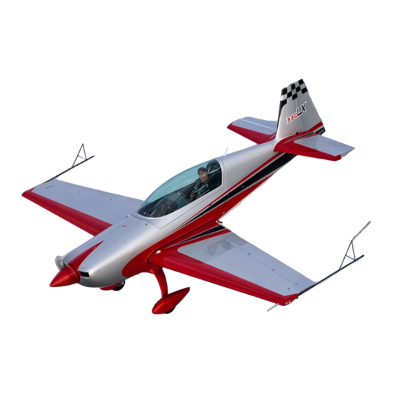
EXTRA 330LX
MANUFACTURER
EXTRA Flugzeugproduktions- und Vertriebs- GmbH
Flugplatz Dinslaken
46569 Hünxe, Federal Republic of Germany
W A R N I N G
This is an Information Manual and may be used for general purposes only.
This Information Manual is not kept current.
It must not be used as a substitute for the official FAA approved
Airplane Flight Manual (AFM) / Pilot's Operating Handbook (POH)
required for operation of an U.S. registered airplane.
Advertisement
Chapters
Table of Contents

Subscribe to Our Youtube Channel
Related Manuals for Extra 330lx


Summary of Contents for Extra 330lx
- Page 1 U.S. I N F O R M A T I O N M A N U A L EXTRA 330LX MANUFACTURER EXTRA Flugzeugproduktions- und Vertriebs- GmbH Flugplatz Dinslaken 46569 Hünxe, Federal Republic of Germany W A R N I N G This is an Information Manual and may be used for general purposes only.
- Page 2 Left blank intentionally...
- Page 3 Pilot´s Operating Handbook US EXTRA 330LX SECTION 0 LOG OF REVISIONS Dates of issue for original and revised pages: Date and sign of approval: Original ........19. February 2014 Approved by CSV Project N° 0010009466 Date of Approval ......07. March 2014...
- Page 4 Pilot´s Operating Handbook US EXTRA 330LX LOG OF EFFECTIVE PAGES Page Date Page Date All ........19. February 2014 Page Date: 19. February 2014...
- Page 5 Pilot´s Operating Handbook US EXTRA 330LX Left blank intentionally Page Date: 19. February 2014...
- Page 6 INTRODUCTION This handbook contains 9 sections, and includes the material required to be furnished to the pilot by FAR Part 23. It also contains supplementary data supplied by EXTRA Flugzeug- produktions- und Vertriebs- GmbH. THIS MANUAL IS FURNISHED TO THE CIVIL AVIATION AUTHORITIES AS A PART OF THE CERTIFICATION MATERIAL FOR THIS MODEL.
- Page 7 Pilot´s Operating Handbook US EXTRA 330LX WARNINGS, CAUTIONS AND NOTES The following definitions apply to Warnings, Cautions, and Notes: WARNING => Operating procedures, techniques, etc., which could result in personal injury or loss of life if not carefully followed. CAUTION =>...
- Page 8 Pilot´s Operating Handbook US EXTRA 330LX MAIN TABLE OF CONTENTS Section Page GENERAL LIMITATIONS EMERGENCY PROCEDURES NORMAL PROCEDURES PERFORMANCE WEIGHT & BALANCE/EQUIPMENT LIST AIRPLANE & SYSTEMS DESCRIPTIONS AIRPLANE HANDLING, SERVICE & MAINTENANCE SUPPLEMENTS Page Date: 19. February 2014...
-
Page 9: Table Of Contents
Section 1 Pilot´s Operating Handbook US General EXTRA 330LX SECTION 1 GENERAL Table of Contents Paragraph Page DESCRIPTION ........................1-3 SPECIFICATION OF CLASS ....................1-3 MANUFACTURER ....................... 1-3 TECHNICAL DATA ......................1-3 1.3.1 3-View Drawing ........................1-3 1.3.2 Main Data ..........................1-4 1.3.3... -
Page 10: Page Date: 19. February
Section 1 Pilot´s Operating Handbook US General EXTRA 330LX Left blank intentionally 1 - 2 Page Date: 19. February 2014... -
Page 11: Description
EXTRA 330LX DESCRIPTION The fuselage of the EXTRA 330LX is built of a tig-welded steel-tube construction. Wings, empennage and landing gear are manufactured from composite material. The aircraft is a two-seater with the rear cockpit equipped with a complete set of airplane controls and instruments. -
Page 12: Main Data
Section 1 Pilot´s Operating Handbook US General EXTRA 330LX 1.3.2 MAIN DATA - Length 7.20 m (23.06 ft) - Height 2.62 m ( 8.60 ft) - Span 8.00 m (26.25 ft) - Wheel base 5.12 m (16.80 ft) - Wheel track 1.80 m ( 5.91 ft) -
Page 13: Engine
Section 1 Pilot´s Operating Handbook US General EXTRA 330LX ENGINE Manufacturer: Textron-Lycoming Williamsport Plant PA 17701 USA. Type: Lycoming AEIO-580-B1A Rated power: 315 HP/235 kW @ 2700 RPM 303 HP/226 kW @ 2600 RPM 286 HP/213 kW @ 2400 RPM PROPELLER Manufacturer: MT-Propeller Entwicklung GmbH, Federal Republic of Germany. -
Page 14: Loading
Section 1 Pilot´s Operating Handbook US General EXTRA 330LX OIL (Cont.) Average ambient air Mil-L6082 Mil-22851 temperature grades ashless dispersant grades - 18°C til 21°C SAE 30 SAE 30,40 or 20W40 (0°F - 70°F) - 18°C til 32°C SAE 20W50 SAE 20W50 or 15W50 (0°F - 90°F) -
Page 15: Secondary Terminology
Section 1 Pilot´s Operating Handbook US General EXTRA 330LX Meteorological terminology International standard atmospheric condition Outside air temperature 1.10 SECONDARY TERMINOLOGY Feet/minute Feet = 0.3048 m inch = 2.54 cm Meter Litres US.gal US (liquid) gallon = 3.79 litres US.qt US (liquid) quart = 0.946 litres... -
Page 16: Conversion Table
Section 1 Pilot´s Operating Handbook US General EXTRA 330LX 1.11 CONVERSION TABLE 1 - 8 Page Date: 19. February 2014... - Page 17 Section 2 Pilot´s Operating Handbook US Limitations EXTRA 330LX SECTION 2 LIMITATIONS Table of Contents Paragraph Page GENERAL ..........................2-3 AIR SPEED (IAS) ........................ 2-3 CROSS-WIND COMPONENT ....................2-3 ENGINE ..........................2-3 2.4.1 Fuel ............................. 2-3 2.4.2 Engine Limitations ....................... 2-4 PROPELLER ........................
- Page 18 Section 2 Pilot´s Operating Handbook US Limitations EXTRA 330LX Left blank intentionally 2 - 2 Page Date: 19. February 2014...
-
Page 19: General
This aircraft is certified under FAA Type Certification Data Sheet N° A67EU. Any exceedance of given limitations has to be reported by the pilot so that necessary inspection or maintenance procedures according to the MAINTENANCE MANUAL EXTRA 330LX can be performed . -
Page 20: Engine Limitations
Section 2 Pilot´s Operating Handbook US Limitations EXTRA 330LX 2.4.2 ENGINE LIMITATIONS Maximum Rotational Speed Take-Off and Maximum Continuous: 2600 rpm b) Oil-temperature - Maximum 118°C (245°F) c) Oil capacity - Maximum sump capacity: 15.13 L (16 US.qt) - Minimum sump capacity: 8.51 L... -
Page 21: Propeller
Section 2 Pilot´s Operating Handbook US Limitations EXTRA 330LX PROPELLER MT-Propeller Entwicklung GmbH, Federal Republic of Germany a) Standard: MTV-9-B-C/C198-25, 3-blade constant speed b) Alternative: MTV-14-B-C/C190-130, 4-blade constant speed Maximum rotational speed - Take-Off and Maximum Continuous: 2600 rpm WEIGHT LIMITS... -
Page 22: Acrobatic Maneuvers
Section 2 Pilot´s Operating Handbook US Limitations EXTRA 330LX ACROBATIC MANEUVERS 2.8.1 RESERVED 2.8.2 ACROBATIC FLIGHT The plane is designed for unlimited acrobatics (wing tank must be empty). Inverted flight maneuvers are limited to max 4 minutes. The structure is designed for full aileron control input up to 185 KIAS (343 km/h) in combination with 2/3 of the applicable max. -
Page 23: Load Factor
Section 2 Pilot´s Operating Handbook US Limitations EXTRA 330LX Maneuvers Recommended entry speeds IAS Symbol Remarks min knots (km/h) max knots (km/h) Segment: horizontal Line 45°climbing 80 (148) 90° up 45° diving reduce throttle 90° diving reduce throttle 1/4 Loop climb. -
Page 24: Flight Crew Limits
Section 2 Pilot´s Operating Handbook US Limitations EXTRA 330LX 2.10 FLIGHT CREW LIMITS Minimum crew is one pilot in the rear seat. Solo flying from rear seat only. Maximum 2 persons are allowed. For hearing protection noise supression (passive or active) communication headsets are required. -
Page 25: Operating Placards
Section 2 Pilot´s Operating Handbook US Limitations EXTRA 330LX 2.14.2 OPERATING PLACARDS V = 154 KTS (ACRO) (near each airspeed indicator) The markings and placards installed in this airplane contain operating limitations which must be complied with when operating this airplane in the acrobatic category. Other operating limitations... - Page 26 Section 2 Pilot´s Operating Handbook US Limitations EXTRA 330LX FUEL SELECTOR VALVE WING TANKS usable 120 L (31.7 US GAL) CENTER (ACRO) TANK usable 67 L (17.7 US GAL) (in both cockpits next to the fuel selector) WING TANK MUST BE EMPTY FOR ACROBATICS.
- Page 27 Section 2 Pilot´s Operating Handbook US Limitations EXTRA 330LX PROP HIGH RPM LOW RPM (On RPM control in the rear cockpit) MIXTURE RICH LEAN (On mixture control in the rear cockpit) THROTTLE OPEN CLOSE (Near throttle control in both cockpits)
- Page 28 Section 2 Pilot´s Operating Handbook US Limitations EXTRA 330LX WING TANK DRAIN (Near the LH drain valve in the bottom fuselage cover) CENTER TANK DRAIN (Near the RH drain valve in the bottom fuselage cover) GASCOLATOR DRAIN (Near the drain valve on the RH lower side of the firewall)
- Page 29 Section 2 Pilot´s Operating Handbook US Limitations EXTRA 330LX Approved acrobatic maneuvers and recommended entry airspeeds Maneuvers Airspeeds Maneuvers Airspeeds min KIAS max KIAS min KIAS max KIAS Segment: Horizontal Line Aileron roll 45°climbing Snap roll 90° up "Tail-slide" 45° diving...
-
Page 30: Instrument Markings
Section 2 Pilot´s Operating Handbook US Limitations EXTRA 330LX 2.14.3 INSTRUMENT MARKINGS AIRSPEED INDICATOR green arc 64 KIAS (119 km/h) - 154 KIAS (285 km/h) yellow arc 154 KIAS (285 km/h) - 219 KIAS (406 km/h) red line 219 KIAS (406 km/h) -
Page 31: Kinds Of Operation Equipment List
Section 2 Pilot´s Operating Handbook US Limitations EXTRA 330LX 2.15 KINDS OF OPERATION EQUIPMENT LIST The aircraft may be operated in day VFR when the appropriate equipment is installed and operable. No Pilot's Operating Handbook Supplement grants approval for IFR operation. - Page 32 The asterisks ( * ) used in the above list mean that according to FAR Part 91 „General Operating and Flight Rules" each occupant of an US registered airplane must wear an approved parachute when performing acrobatic maneuvers. Extra Flugzeugproduktions- und Vertriebs- GmbH considers acrobatics without wearing an approved parachute to be unsafe. 2 - 16...
- Page 33 Pilot´s Operating Handbook US Section 3 EXTRA 330LX Emergency Procedures SECTION 3 EMERGENCY PROCEDURE Table of Contents Paragraph Page INTRODUCTION ........................3-3 3.0.1 General ..........................3-3 3.0.2 General Behaviour in Emergency Situations ................. 3-3 AIRSPEEDS FOR EMERGENCY OPERATION ..............3-4 OPERATIONAL CHECKLIST ....................
- Page 34 Pilot´s Operating Handbook US Section 3 EXTRA 330LX Emergency Procedures Left blank intentionally 3 - 2 Page Date: 19. February 2014...
-
Page 35: Introduction
Pilot´s Operating Handbook US Section 3 EXTRA 330LX Emergency Procedures INTRODUCTION 3.0.1 GENERAL This section contains the checklist and procedures coping with emergencies that may occur. This checklist must be followed in various emergencies to ensure maximum safety for the crew and/or aircraft. -
Page 36: Airspeeds For Emergency Operation
Pilot´s Operating Handbook US Section 3 EXTRA 330LX Emergency Procedures AIRSPEEDS FOR EMERGENCY OPERATION Stall speed 64 KIAS (119 km/h) Engine failure after take-off 90 KIAS (167 km/h) Best recommended gliding speed (glide angle 1 : 6,2) -Acro III Category... -
Page 37: Loss Of Oil Pressure
Pilot´s Operating Handbook US Section 3 EXTRA 330LX Emergency Procedures 3.2.4 LOSS OF OIL PRESSURE 1. Positive "g" Apply If oil pressure is not regained then: 2. Airspeed 90 KIAS (167 km/h) 3. Throttle REDUCE AS REQUIRED 4. Engine oil temperature OBSERVE INDICATION 5. -
Page 38: Forced Landings
Pilot´s Operating Handbook US Section 3 EXTRA 330LX Emergency Procedures FORCED LANDINGS 3.3.1 EMERGENCY LANDING WITHOUT ENGINE POWER 1. Seat belts, shoulder harnesses SECURE 2. Airspeed 90 KIAS (167 km/h) 3. Mixture IDLE CUT OFF 4. Fuel shutoff valve OFF (Pull & Turn) 5. -
Page 39: If Engine Fails To Start
Pilot´s Operating Handbook US Section 3 EXTRA 330LX Emergency Procedures 3.4.2 IF ENGINE FAILS TO START 1. Cranking CONTINUE 2. Throttle FULL OPEN 3. Mixture IDLE CUT OFF 4. Fuel shutoff valve OFF (Pull & Turn) If fire is extinguished: 5. -
Page 40: Emergency Exit After Turn Over
Pilot´s Operating Handbook US Section 3 EXTRA 330LX Emergency Procedures EMERGENCY EXIT AFTER TURN OVER 1. Battery switch 2. Alternator switch 3. Fuel shutoff valve OFF (Pull & Turn) 4. Seat belts OPEN 5. Parachute harnesses (if wearing a parachute) OPEN 6. - Page 41 Section 4 Pilot´s Operating Handbook US Normal Procedures EXTRA 330LX SECTION 4 NORMAL PROCEDURES Table of Contents Paragraph Page GENERAL ..........................4-3 4.0.1 Airspeeds for Normal Operation ................... 4-3 4.0.2 Checklist and Procedures ....................4-3 PREFLIGHT INSPECTION ....................4-4 CHECKLIST PROCEDURES ....................4-4 STARTING PROCEDURES ....................
- Page 42 Section 4 Pilot´s Operating Handbook US Normal Procedures EXTRA 330LX Left blank intentionally 4 - 2 Page Date: 19. February 2014...
-
Page 43: General
Section 4 Pilot´s Operating Handbook US Normal Procedures EXTRA 330LX GENERAL 4.0.1 AIRSPEEDS FOR NORMAL OPERATION CATEGORY ACRO I ACRO II ACRO III 820 kg 870 kg 950 kg (1808 lbs) (1918 lbs) (2095 lbs) KIAS (km/h) KIAS (km/h) KIAS (km/h) -
Page 44: Preflight Inspection
Section 4 Pilot´s Operating Handbook US Normal Procedures EXTRA 330LX PREFLIGHT INSPECTION 4.1.1 EXTERIOR INSPECTION ILLUSTRATION 4.1.2 GENERAL Visually check airplane for general condition during walk around inspection. Perform exterior check as outlined in the picture above in counterclockwise direction. - Page 45 Section 4 Pilot´s Operating Handbook US Normal Procedures EXTRA 330LX 6. Wing fuel tank drain DRAIN FOR AT LEAST 4 SECONDS TO CLEAR SUMP OF POSSIBLE WATER; CHECK CLOSED 7. Right landing gear, wheel CHECK 8. Stall warning vane CHECK 4) Nose 1.
-
Page 46: Starting Procedures
Section 4 Pilot´s Operating Handbook US Normal Procedures EXTRA 330LX STARTING PROCEDURES 4.3.1 COLD ENGINES The following starting procedures are recommended, however, the starting conditions may necessitate some variation from these procedures. 1. Perform pre-flight inspection. 2. Set propeller governor control to "High RPM" position. -
Page 47: Take-Off Procedure
Section 4 Pilot´s Operating Handbook US Normal Procedures EXTRA 330LX TAKE-OFF PROCEDURE 4.5.1 BEFORE TAKE-OFF Before you line up at the runway for take-off: Oil pressure and oil temperature CHECK Magnetos CHECK as follows: Engine RPM: 1800 min Pay attation to the three small LEDs in the "Status" area on the upper left corner of... -
Page 48: Climb
Section 4 Pilot´s Operating Handbook US Normal Procedures EXTRA 330LX CLIMB Climbs may be performed up to maximum continuous RPM. RPM above 2400 should, however, be used only when necessary for maximum performance in order to avoid unnecessary noise. Turn boost pump "OFF". -
Page 49: Normal Landing
Section 4 Pilot´s Operating Handbook US Normal Procedures EXTRA 330LX N O T E Stall speed will be: MTOW = 820 kg (1808 lbs): 59 KIAS (109 km/h) MTOW = 870 kg (1918 lbs): 61 KIAS (113 km/h) MTOW = 950 kg (2095 lbs): 64 KIAS (119 km/h) 4.8.4... -
Page 50: Acrobatic Maneuvers
Section 4 Pilot´s Operating Handbook US Normal Procedures EXTRA 330LX 4.12 ACROBATIC MANEUVERS 4.12.1 GENERAL N O T E Prior to executing these maneuvers tighten harnesses and check all loose items are stowed. Start the maneuvers at safe altitude and maximum continuous power setting if not otherwise noted. - Page 51 Section 4 Pilot´s Operating Handbook US Normal Procedures EXTRA 330LX - Segment line 90° up: Any entry speed may be used. Out of a horizontal pull-up at 200 KIAS (370 km/h) the vertical penetration will be 2.500 ft. The speed will gradually decrease to 0.
-
Page 52: Spin
Section 4 Pilot´s Operating Handbook US Normal Procedures EXTRA 330LX 4.12.3 SPIN To enter a spin proceed as follows: - Reduce speed, power idle - When the plane stalls: - Kick rudder to desired spin direction - Hold ailerons neutral - Stick back (positive spinning), stick forward (negative spinning) The plane will immediately enter a stable spin. - Page 53 Pilot´s Operating Handbook US Normal Procedures EXTRA 330LX No determination has been made by the Federal Aviation Administration that the noise levels of this aircraft are or should be acceptable or unacceptable for operation at, into, or out of any airport.
- Page 54 Section 4 Pilot´s Operating Handbook US Normal Procedures EXTRA 330LX Left blank intentionally 4 - 14 Page Date: 19. February 2014...
- Page 55 Section 5 Pilot´s Operating Handbook US Performance EXTRA 330LX SECTION 5 PERFORMANCE Table of Contents Paragraph Page SECTION 5 GENERAL ..........................5-3 5.1.1 Performance Charts ......................5-3 5.1.2 Definitions of Terms ......................5-3 5.1.3 Sample Problem ........................5-3 ISA CONVERSION ......................5-5 AIRSPEED CALIBRATION ....................
- Page 56 Section 5 Pilot´s Operating Handbook US Performance EXTRA 330LX Left blank intentionally 5 - 2 Page Date: 19. February 2014...
-
Page 57: General
Section 5 Pilot´s Operating Handbook US Performance EXTRA 330LX SECTION 5 PERFORMANCE GENERAL Performance data charts on the following pages are presented to facilitate the planning of flights in detail and with reasonable accuracy under various conditions. The data in the charts have been computed from actual flight tests with the aircraft and engine in good condition and using average piloting techniques. - Page 58 Section 5 Pilot´s Operating Handbook US Performance EXTRA 330LX TAKE-OFF Take-Off Distance is shown by Fig. 5.5 Example: -T/O Weight: 870 kg (1918 lbs) -Ground Roll: 112 m (367 ft) -Total Distance to clear a 50 ft obstacle: 248 m (813 ft) These distances are well within the available field length incl.
-
Page 59: Isa Conversion
Section 5 Pilot´s Operating Handbook US Performance EXTRA 330LX ISA CONVERSION ISA Conversion of pressure altitude and outside air temperature Page Date: 19. February 2014 5 - 5... -
Page 60: Airspeed Calibration
Section 5 Pilot´s Operating Handbook US Performance EXTRA 330LX AIRSPEED CALIBRATION CAS [km/h] 110 130 150 170 190 210 230 250 270 290 310 330 350 370 390 410 90 100 110 120 130 140 150 160 170 180 190 200 210 220... -
Page 61: Stall Speed
Section 5 Pilot´s Operating Handbook US Performance EXTRA 330LX STALL SPEED CONDITION: POWER IDLE FORWARD C/G STALL SPEEDS ANGLE OF BANK WEIGHT CATEGORY 0° 30° 45° 60° 1,15 g 1,41 g kg (lbs) KIAS (km/h) KIAS (km/h) KIAS (km/h) KIAS (km/h) -
Page 62: Take-Off Performance
Section 5 Pilot´s Operating Handbook US Performance EXTRA 330LX TAKE-OFF PERFORMANCE Power : T/O Power Runway: Concrete N O T E For every 5 kts (9 km/h) headwind, the T/O distance can be decreased by 4%. For every 3 kts (6 km/h) tailwind [up to 10 kts (19 km/h)], the T/O distance is increased by 10%. -
Page 63: Rate Of Climb Performance
Section 5 Pilot´s Operating Handbook US Performance EXTRA 330LX RATE OF CLIMB PERFORMANCE Page Date: 19. February 2014 5 - 9... -
Page 64: Time To Climb, Fuel To Climb
Section 5 Pilot´s Operating Handbook US Performance EXTRA 330LX TIME TO CLIMB, FUEL TO CLIMB 5 - 10 Page Date: 19. February 2014... -
Page 65: Range
Section 5 Pilot´s Operating Handbook US Performance EXTRA 330LX RANGE Page Date: 19. February 2014 5 - 11... -
Page 66: Endurance
Section 5 Pilot´s Operating Handbook US Performance EXTRA 330LX ENDURANCE 5 - 12 Page Date: 19. February 2014... -
Page 67: Cruise Performance
Section 5 Pilot´s Operating Handbook US Performance EXTRA 330LX 5.10 CRUISE PERFORMANCE Configuration: T/O Weight 950 kg (2095 lb) Acro & Center Tank Fuel Capacity 69 L (18.2 US gal) Total Fuel Capacity 189 L (49.9 US gal) Range and Endurance values include fuel for warm-up and Take-Off from SL, max. cont. Power climb to cruising altitude, and a reserve of 21 L (5.55 US gal) for 45 minutes with 45% Power. -
Page 68: Landing Performance
Section 5 Pilot´s Operating Handbook US Performance EXTRA 330LX 5.11 LANDING PERFORMANCE Power : Idle Runway: Concrete Brakes: maximum N O T E For every knot (1.852 km/h) headwind, the landing distance can be decreased by 3%. On a solid, dry and plain grass runway, the landing is increased by 15%. - Page 69 Section 6 Pilot´s Operating Handbook US Weight and Balance and Equipment List EXTRA 330LX SECTION 6 WEIGHT AND BALANCE AND EQUIPMENT LIST Table of Contents Paragraph Page SECTION 6 WEIGHT AND BALANCE AND EQUIPMENT LIST GENERAL ..........................6-3 AIRCRAFT WEIGHING PROCEDURE ................. 6-3 6.2.1...
- Page 70 Section 6 Pilot´s Operating Handbook US Weight and Balance and Equipment List EXTRA 330LX Left blank intentionally 6 - 2 Page Date: 19. February 2014...
-
Page 71: General
Section 6 Pilot´s Operating Handbook US Weight and Balance and Equipment List EXTRA 330LX GENERAL This section describes the procedure for establishing the basic weight and moment of the aircraft. Sample forms are provided for reference. Procedures for calculating the weight and movement for various operations are also provided. -
Page 72: Owners Weight And Balance Record
Section 6 Pilot´s Operating Handbook US Weight and Balance and Equipment List EXTRA 330LX If a new weight is added to the known old weight and CG position the resulting new weight and CG can be obtained by a simple calculation:... -
Page 73: Center Of Gravity Calculation (Sample Problem)
Section 6 Pilot´s Operating Handbook US Weight and Balance and Equipment List EXTRA 330LX CENTER OF GRAVITY CALCULATION (SAMPLE PROBLEM) PILOT ACRO-TANK COPILOT WING-TANK Rear Seat Fuel Front Seat Fuel Position 51 LTR 120 LTR (13.4 US GAL) (31,7 US GAL) - Page 74 Section 6 Pilot´s Operating Handbook US Weight and Balance and Equipment List EXTRA 330LX 6 - 6 Page Date: 19. February 2014...
-
Page 75: Sample
Section 6 Pilot´s Operating Handbook US Weight and Balance and Equipment List EXTRA 330LX 6.3.1 Sample Take-off Condition: Pilot On Rear Seat 90.0 kg ( 198.5 lbs) Copilot On Front Seat 90.0 kg ( 198.5 lbs) 51 L Fuel in Acro Tanks 37.0 kg... -
Page 76: Loading Weights And Moments
Section 6 Pilot´s Operating Handbook US Weight and Balance and Equipment List EXTRA 330LX LOADING WEIGHTS AND MOMENTS OCCUPANTS : max. 2 PILOT COPILOT WEIGHT REAR SEAT FRONT SEAT Pilot + Parachute Arm = 207cm (81.5 inch) Arm = 98 cm (38.4 inch) -
Page 77: Weights And Moments Limits
Section 6 Pilot´s Operating Handbook US Weight and Balance and Equipment List EXTRA 330LX WEIGHTS AND MOMENTS LIMITS EXAMPLE: At 790 KG (1741 LBS) and 640000 kgcm the C/G location is 80.0 cm (31.4") aft of ref datum Page Date: 19. February 2014... -
Page 78: Equipment List
Section 6 Pilot´s Operating Handbook US Weight and Balance and Equipment List EXTRA 330LX EQUIPMENT LIST EXTRA 330LX S/N: QTY ITEM MANUFACT. MODEL NO PART OR P/N WEIGHT ARM R* INST (kg) Mooring (10) Wing Tie Down Rings Extra 8C801.002 0.05... - Page 79 Section 6 Pilot´s Operating Handbook US Weight and Balance and Equipment List EXTRA 330LX QTY ITEM MANUFACT. MODEL NO PART OR P/N WEIGHT ARM R* INST (kg) Electrically Extra EA-86612 7.28 1.10 Adjustable Pedals Sys. Fuel System (28) Elec. Fuel Pump...
- Page 80 Section 6 Pilot´s Operating Handbook US Weight and Balance and Equipment List EXTRA 330LX QTY ITEM MANUFACT. MODEL NO PART OR P/N WEIGHT ARM R* INST (kg) Airspeed Ind. front (kts) Mikrotechna Praha LUN 1106.K2B4/SC 34155 0.50 0.65 reserved Airspeed Indicator United Instr.
- Page 81 Optional Clock Digital Clock Astrotech LC-2 FI0004 0.14 1.60 Optional Aerobatics Equipment Aresti-Card Holder Extra EA-83504.4 EA-83504. 0.09 1.66 004-PG Aresti-Card Holder (Aspen) Extra EA-86504.4 EA-86504. 0.09 1.66 004-PG Sighting device Extra EA-8E801.30 0.55 1.60 (45°/90°) Smoke System Extra 86112 9.20...
- Page 82 33902-PG 1.00 1.53 Cowling (54) Cowling (CRP) Extra EA-83001.0 9.20 -0.57 Cowling (GRP) Extra EA-83003.0 10.60 -0.57 Cowling (CRP, incl. Landing Extra EA-8E001.0 9.20 -0.57 Light provision) Canopy (56) Standard Canopy Extra 26301.000-LV 26301.000-VF 13.50 1.69 Single Seat Canopy Extra EA-86411.0...
- Page 83 Section 6 Pilot´s Operating Handbook US Weight and Balance and Equipment List EXTRA 330LX QTY ITEM MANUFACT. MODEL NO PART OR P/N WEIGHT ARM R* INST (kg) Powerplant (7X) Engine Engine Lycoming AEIO-580-B1A 32712 191.72 -0.72 (R/H)ENPL-RT10427 Shock Mount Barry...
- Page 84 Section 6 Pilot´s Operating Handbook US Weight and Balance and Equipment List EXTRA 330LX QTY ITEM MANUFACT. MODEL NO PART OR P/N WEIGHT ARM R* INST (kg) Optional add on to convent eng. Gauges Fuel Scan Sys. FS-450 30611-PG 0.18 0.98...
- Page 85 Section 7 Pilot´s Operating Handbook US Description and Operation of Aircraft and Systems EXTRA 330LX SECTION 7 DESCPRIPTION & OPERATION OF AIRCRAFT AND SYSTEMS Table of Contents Paragraph Page THE AIRCRAFT ........................7-3 FUSELAGE ......................... 7-3 WINGS ..........................7-4 EMPENNAGE ........................7-4 FLIGHT CONTROL SYSTEM ....................
- Page 86 Section 7 Pilot´s Operating Handbook US Description and Operation of Aircraft and Systems EXTRA 330LX Left blank intentionally 7 - 2 Page Date: 19. February 2014...
-
Page 87: The Aircraft
EXTRA 330LX is a light weight, robust, single piston-engined, two-seat aircraft with a fuselage structure in tig-welded steel-tube construction. The landing gear, wing, and tail are made of epoxy, reinforced with glass- and carbonfiber. -
Page 88: Wings
EMPENNAGE The EXTRA 330LX possesses a cruziform empennage with stabilizers and moveable control surfaces. The rudder is balanced aerodynamically at the tip. Spars consist of PVC foam cores, CRP caps and CRP laminates. -
Page 89: Flight Control System
FLIGHT CONTROL SYSTEM 7.5.1 PRIMARY CONTROL SYSTEM The EXTRA 330LX is standard equipped with full dual primary flight controls including front and rear sticks and adjustable rudder pedals. The primary control surfaces are operated through a direct mechanical linkage. 7.5.2 LONGITUDINAL FLIGHT CONTROL SYSTEM Front and rear sticks are interconnected by a push rod inside the torque tube. -
Page 90: Instrument Panel (Rear Cockpit)
Section 7 Pilot´s Operating Handbook US Description and Operation of Aircraft and Systems EXTRA 330LX 7.6.1 INSTRUMENT PANEL (REAR COCKPIT) Figure 1, Instrument Panel Figure 2, Switches, Circuit Breaker 7 - 6 Page Date: 19. February 2014... - Page 91 Section 7 Pilot´s Operating Handbook US Description and Operation of Aircraft and Systems EXTRA 330LX Position Item Fig. 1 G-meter Volt/Amperemeter Airspeed indicator Magn. direction indicator Altimeter Manifold pressure / fuel flow RPM Indicator Trim position indicator Transponder Magneto selector switch and starter...
-
Page 92: Instrument Panel (Front Cockpit)
Section 7 Pilot´s Operating Handbook US Description and Operation of Aircraft and Systems EXTRA 330LX 7.6.2 INSTRUMENT PANEL (FRONT COCKPIT) Normally the instument panel in the front cockpit is only equipped with: - Airspeed indicator - Altimeter indicator. LANDING GEAR The landing gear is a composite construction with a multichamber fiberglass spring in a tail-wheel design. -
Page 93: Power Plant
Section 7 Pilot´s Operating Handbook US Description and Operation of Aircraft and Systems EXTRA 330LX 7.10 POWER PLANT 7.10.1 ENGINE The power plant consists of one Textron-Lycoming six-cylinder, horizontally opposed, aircooled, direct drive, fuel injection engine type with inverted oil system. -
Page 94: Engine Installation
Position up = WING TANK 7.10.9 EXHAUST SYSTEM A complete Gomolzig 6 in 1 System with integrated silencer is installed on the 330LX. 7.11 FUEL SYSTEM The fuel system (refer to Figure 3) consists of two separate, independent tanks: - Acro & center tank in the fuselage... - Page 95 Section 7 Pilot´s Operating Handbook US Description and Operation of Aircraft and Systems EXTRA 330LX Figure 3, Fuel System Page Date: 19. February 2014 7 - 11...
-
Page 96: Electrical System
Section 7 Pilot´s Operating Handbook US Description and Operation of Aircraft and Systems EXTRA 330LX Wing Tank: The root section of each wing - in front of main spars forms an integral fuel tank providing two interconnected tanks with 120 liters (31,7 US GAL.) total capacity. Each side of the wing has a 2"... - Page 97 Section 7 Pilot´s Operating Handbook US Description and Operation of Aircraft and Systems EXTRA 330LX Figure 4, Electrical System Page Date: 19. February 2014 7 - 13...
- Page 98 Section 7 Pilot´s Operating Handbook US Description and Operation of Aircraft and Systems EXTRA 330LX Left blank intentionally 7 - 14 Page Date: 19. February 2014...
- Page 99 Section 8 Pilot´s Operating Handbook US Handling, Servicing and Maintenance EXTRA 330LX SECTION 8 HANDLING, SERVICING & MAINTENANCE TABLE OF CONTENTS Paragraph Page INTRODUCTION ........................8-3 AIRPLANE INSPECTION PERIODS ..................8-3 PILOT CONDUCTED PREVENTIVE MAINTENANCE ............8-3 ALTERATIONS OR REPAIR ....................8-3 SERVICING .........................
- Page 100 Section 8 Pilot´s Operating Handbook US Handling, Servicing and Maintenance EXTRA 330LX Left blank intentionally 8 - 2 Page Date: 19. February 2014...
-
Page 101: Introduction
Section 8 Pilot´s Operating Handbook US Handling, Servicing and Maintenance EXTRA 330LX SECTION 8 HANDLING, SERVICING AND MAINTENANCE INTRODUCTION a) The airplane owner should establish contact with the dealer or certified service station for service and information. b) All correspondence regarding the airplane must include its serial number which is stamped on a plate on the L/H rear part of the fuselage. -
Page 102: Servicing
Section 8 Pilot´s Operating Handbook US Handling, Servicing and Maintenance EXTRA 330LX SERVICING In addition to the airplane inspection periods (8.2) information for servicing the aircraft with proper oil and fuel is covered in Section 2 (Limitations) and Section 7 (Description and Operation). - Page 103 Pilot´s Operating Handbook US Section 9 EXTRA 330LX Supplements SECTION 9 SECTION 9 SUPPLEMENTS SECTION 9 SUPPLEMENTS Doc-No. EA-0E701US.1 SUPPLEMENTS ........................3 Table of Contents Section Pages Supplements ........................4 p. Steerable Tail Wheel ..................... 4 p. Electric Pedal Adjustment ..................... 4 p.
- Page 104 Section 9 Pilot´s Operating Handbook US Supplements EXTRA 330LX Left blank intentionally 9 - 2 Page Date: 19. February 2014...
- Page 105 The described systems and equipment are certified by the EASA on behalf of the FAA for the EXTRA 330LX. Pages and contents of this section must not be exchanged and alterations of or additions to the approved contents must not be made without the EXTRA Flugzeugproduktions- und Vertriebs- GmbH/FAA approval.
- Page 106 Section 9 Pilot´s Operating Handbook US Supplements EXTRA 330LX Left blank intentionally 9 - 4 Page Date: 19. February 2014...
- Page 107 Section 901 Pilot´s Operating Handbook US Steerable Tail Wheel EXTRA 330LX SECTION 901 STEERABLE TAIL WHEEL Table of Contents Paragraph Page 901.1 GENERAL ......................... 901-3 901.2 LIMITATION ........................901-3 901.3 EMERGENCY PROCEDURES ................... 901-3 901.4 NORMAL PROCEDURES ....................901-3 901.5 PERFORMANCE ......................
- Page 108 Section 901 Pilot´s Operating Handbook US Steerable Tail Wheel EXTRA 330LX Left blank intentionally 901 - 2 Page Date: 19. Februar 2014...
-
Page 109: General
901.1 GENERAL To improve taxi and handling quality, the EXTRA 330LX can be equipped with an optional steerable tailwheel. The deflection angle of this tailwheel is arranged by the rudder control up to plus/minus 30°. Exceeding this deflection the tailwheel has a full-swivel capability by a release mechanism. - Page 110 Section 901 Pilot´s Operating Handbook US Steerable Tail Wheel EXTRA 330LX 901.8 HANDLING, SERVICING AND MAINTENANCE During 50 hour inspection, the bearing steel sleeve has to be lubricated on the point of lubri- cating. Additionally all parts of the tailwheel have to be inspected visually for deformations, cracks and corrosion.
- Page 111 Pilot´s Operating Handbook US Section 902 EXTRA 330LX Electric Pedal Adjustment SECTION 902 ELECTRIC PEDAL ADJUSTMENT Table of Contents Paragraph Page 902.1 GENERAL ......................... 902-3 902.2 LIMITATIONS ........................902-3 902.3 EMERGENCY PROCEDURES ................... 902-3 902.4 NORMAL PROCEDURES ....................902-3 902.5 PERFORMANCE ......................
- Page 112 Section 902 Pilot´s Operating Handbook US Electric Pedal Adjustment EXTRA 330LX Left blank intentionally 902 - 2 Page Date: 19. Februar 2014...
- Page 113 902.1 GENERAL To improve seat and control convenience, the EXTRA 330LX is equipped with an electric pedal adjustment system. The pedal adjustment system provides an in-flight capability to adjust the pedals according the pilots size and operation. For example a more relaxed, stretched seating position for long cross-country flights is possible.
- Page 114 Section 902 Pilot´s Operating Handbook US Electric Pedal Adjustment EXTRA 330LX 902.7 DESCRIPTION OF THE SYSTEM The electrical pedal adjustment system consists of a foot rest and the rudder pedal itself, including brake pedal and brake cylinder. An S-shaped cable leader is attached to the rudder pedal, through which the control cable runs from the rudder actuator arm to the front cable attachment at the steel frame.
- Page 115 Section 903 Pilot´s Operating Handbook US Cabin Heating System EXTRA 330LX SECTION 903 CABIN HEATING SYSTEM Table of Contents Paragraph Page 903.1 GENERAL ......................... 903-3 903.2 LIMITATIONS ........................903-3 903.3 EMERGENCY PROCEDURES ................... 903-3 903.4 NORMAL PROCEDURES ....................903-3 903.5 PERFORMANCE ......................
- Page 116 Section 903 Pilot´s Operating Handbook US Cabin Heating System EXTRA 330LX Left blank intentionally 903 - 2 Page Date: 19. February 2014...
- Page 117 903.1 GENERAL The 330LX can be equipped with a cabin heating system, which allows feeding the front and rear cockpit independently with warm air. The system uses fresh outside air, which is heated up by the engine exhaust muffler. The system is controlled by two handles in the rear cockpit.
- Page 118 Section 903 Pilot´s Operating Handbook US Cabin Heating System EXTRA 330LX 903.7 SYSTEM DESCRIPTION On the left front engine baffle a 3” air intake (1, figure 1) with screen is positioned. From there fresh air is routed through a 3" ducting (2) to the exhaust muffler heat shroud (3), where it is heated up.
- Page 119 Pilot´s Operating Handbook US Section 904 EXTRA 330LX Accelerometer TL-3424_EXT SECTION 904 ACCELEROMETER TL-3424_EXT Table of Contents Paragraph Page 904.1 GENERAL ......................... 904-3 904.2 LIMITATIONS ........................904-3 904.3 EMERGENCY PROCEDURES ................... 904-3 904.4 NORMAL PROCEDURES ....................904-3 904.5 PERFORMANCE ......................904-3 904.6...
- Page 120 Section 904 Pilot´s Operating Handbook US Accelerometer TL-3424_EXT EXTRA 330LX Left blank intentionally 904 - 2 Page Date: 19. February 2014...
- Page 121 ACCELEROMETER TL-3424_EXT 904.1 GENERAL The TL-3424_EXT accelerometer can be installed as an option in the EXTRA 330LX. It is used in a special password protected configuration. This configuration helps the pilot to operate the aircraft within limits. In detail the TL-3424_EXT accelerometer allows: 1.
- Page 122 Section 904 Pilot´s Operating Handbook US Accelerometer TL-3424_EXT EXTRA 330LX 904.6 WEIGHT AND BALANCE Refer to the Equipment List in Section 6 of this Handbook. 904.7 DESCRIPTION The complete installation consists of: 1 TL-3424_EXT Accelerometer 2 G/V LIMITS WARNING LIGHT 3 RS-232c (D-SUB 9 pins [female]) The TL-3424_EXT is complete weight acceleration management.
- Page 123 Pilot´s Operating Handbook US Section 904 EXTRA 330LX Accelerometer TL-3424_EXT The TL-3424_EXT checks all measured values at two levels - for a warning and an alarm limit signalization. If the measured values are above the warning limit and below the alarm limit an intermitted sound is heard on the head set and the G/V LIMIT WARNING LIGHT flashes.
- Page 124 Section 904 Pilot´s Operating Handbook US Accelerometer TL-3424_EXT EXTRA 330LX SYMBOLS The following symbols are used in the TL-3424_EXT display. Display Symbol Meaning recording to memory Recording paused Acceleration values indicated up/down arrows storing expected, release buttons when setting arrows vanish CONTROLLING THE INSTRUMENT VIA NAV-MENU There are black labels on the display.
- Page 125 Pilot´s Operating Handbook US Section 905 EXTRA 330LX External Power SECTION 905 EXTERNAL POWER Table of Contents Paragraph Page 905.1 GENERAL ........................905-3 905.2 LIMITATIONS ........................905-3 905.3 EMERGENCY PROCEDURES ..................905-3 905.4 NORMAL PROCEDURES ....................905-3 905.5 PERFORMANCE ......................905-4 905.6...
- Page 126 Section 905 Pilot´s Operating Handbook US External Power EXTRA 330LX Left blank intentionally 905 - 2 Page Date: 19. February 2014...
- Page 127 EXTERNAL POWER 905.1 GENERAL The EXTRA 330LX can be equipped with an external power receptacle system. This system provides the capability to start the engine independent of the board battery and further allows feeding the electrical system for longer periods.
-
Page 128: Performance
Section 905 Pilot´s Operating Handbook US External Power EXTRA 330LX CAUTION Pay attention to objects and persons in the propeller operating area! Hold the canopy tight! 8. Apply the brakes. 9. Engage starter. 10.When engine fires release the ignition switch back to "BOTH". - Page 129 Pilot´s Operating Handbook US Section 906 EXTRA 330LX Digital RPM Indicator SECTION 906 DIGITAL RPM INDICATOR Table of Contents Paragraph Page 906.1 GENERAL ......................... 906-3 906.2 LIMITATIONS ........................906-3 906.3 EMERGENCY PROCEDURES ................... 906-3 906.4 NORMAL PROCEDURES ....................906-3 906.5 PERFORMANCE ......................
- Page 130 Section 906 Pilot´s Operating Handbook US Digital RPM Indicator EXTRA 330LX Left blank intentionally 906 - 2 Page Date: 19. February 2014...
- Page 131 EXTRA 330LX Digital RPM Indicator DIGITAL RPM INDICATOR 906.1 GENERAL The EXTRA 330LX is as standard equipped with an "P-1000" Digital rpm indicator. The following model is used: P100-230-635-00 (max. 2600 rpm) 906.2 LIMITATIONS The operation limitations are not affected by the installation of the "P-1000" Digital RPM indicator.
- Page 132 Section 906 Pilot´s Operating Handbook US Digital RPM Indicator EXTRA 330LX Magneto-Control RPM range RPM- restriction Status Display Operation placard: Hours Clear Trap Press-and-hold Operation placard: buttons Press-and-release 906.6 WEIGHT AND BALANCE Refer to the Equipment List in Section 6 of this Handbook.
- Page 133 Pilot´s Operating Handbook US Section 906 EXTRA 330LX Digital RPM Indicator RPM RANGES The face of the indicator is placarded with the respective engine rpm operating range. Additionally the engine operating ranges are indicated by the large green, yellow, and red LEDs.
- Page 134 Section 906 Pilot´s Operating Handbook US Digital RPM Indicator EXTRA 330LX PRESS-AND-RELEASE operation mode (press and release in less than 2/3 of a second) This operation mode is placarded below each button.(L , DIM , R) Masks (L , R) During normal operation, the tachometer presents the average of the left and right internal tachometers on the display.
- Page 135 Pilot´s Operating Handbook US Section 907 EXTRA 330LX Smoke System SECTION 907 SMOKE SYSTEM Table of Contents Paragraph Page 907.1 GENERAL ......................... 907-3 907.2 LIMITATIONS ........................907-3 907.3 EMERGENCY PROCEDURES ................... 907-3 907.4 NORMAL PROCEDURES ....................907-4 907.5 PERFORMANCE ......................907-5 907.6...
- Page 136 Section 907 Pilot´s Operating Handbook US Smoke System EXTRA 330LX Left blank intentionally 907 - 2 Page Date: 19. February 2014...
- Page 137 EXTRA 330LX Smoke System SMOKE SYSTEM 907.1 GENERAL For performing at airshows, the EXTRA 330LX may optionally be equipped with a smoke system. 907.2 LIMITATIONS For safe operation of the smoke system the following limitations have to be considered: 1) The load factor and "MTOW" are limited to:...
- Page 138 Section 907 Pilot´s Operating Handbook US Smoke System EXTRA 330LX FIRE IN FLIGHT 1. Switch "SMOKE ARM" CAUTION If the fire (after the smoke system is shut off) will not extinguish proceed as follows: 2. Mixture IDLE CUT OFF 3. Fuel selector valve OFF (Pull &...
- Page 139 Pilot´s Operating Handbook US Section 907 EXTRA 330LX Smoke System CAUTION A shut-off failure of the refill process can be recognized by smoke oil spilling out of the vent line. In this case, turn off refill switch. The floating device switch in the main smoke oil tank has to be checked accordingly.
- Page 140 Pilot´s Operating Handbook US Smoke System EXTRA 330LX throttle lever. For filling the smoke oil tanks the "SMOKE REFILL" switch needs to be ON. After the refill process is completed the "SMOKE REFILL" has to switched OFF. When both switches ("SMOKE ARM"...
- Page 141 Pilot´s Operating Handbook US Section 907 EXTRA 330LX Smoke System 907.8 HANDLING, SERVICING AND MAINTENANCE At every refilling: - Check automatic shut-off Additionally during the 100h Check - Check the system for leakage (lines, fittings, tanks) - Check the smoke oil tanks for proper attachment...
- Page 142 Section 907 Pilot´s Operating Handbook US Smoke System EXTRA 330LX Left blank intentionally 907 - 8 Page Date: 19. February 2014...
- Page 143 Pilot´s Operating Handbook US Section 908 EXTRA 330LX Single Seat Canopy SECTION 908 SINGLE SEAT CANOPY Table of Contents Paragraph Page 908.1 GENERAL ......................... 908-3 908.2 LIMITATIONS ........................908-3 908.3 EMERGENCY PROCEDURES ................... 908-3 908.4 NORMAL PROCEDURES ....................908-3 908.5 PERFORMANCE ......................
- Page 144 Section 908 Pilot´s Operating Handbook US Single Seat Canopy EXTRA 330LX Left blank intentionally 908 - 2 Page Date: 19. February 2014...
- Page 145 Pilot´s Operating Handbook US Section 908 EXTRA 330LX Single Seat Canopy SINGLE SEAT CANOPY 908.1 GENERAL For airshow performances the standard canopy can be replaced by a single seat canopy, which gives a gorgeous appearance. 908.2 LIMITATIONS With the single seat canopy installed the aircraft is limited to the category ACRO I.
- Page 146 Section 908 Pilot´s Operating Handbook US Single Seat Canopy EXTRA 330LX Left blank intentionally 908 - 4 Page Date: 19. February 2014...
- Page 147 Section 909 Pilot´s Operating Handbook US ARTEX ME-406 ELT EXTRA 330LX SECTION 909 ARTEX ME-406 ELT Table of Contents Paragraph Page 909.1 GENERAL ......................... 909-3 909.2 LIMITATIONS ........................909-3 909.3 EMERGENCY PROCEDURES ................... 909-4 909.4 NORMAL PROCEDURES ....................909-4 909.5 PERFORMANCE ......................
- Page 148 Section 909 Pilot´s Operating Handbook US ARTEX ME-406 ELT EXTRA 330LX Left blank intentionally 909 - 2 Page Date: 19. February 2014...
-
Page 149: General
EXTRA 330LX 909.1 GENERAL To improve the passive security, the EXTRA 330LX can be equipped with an optional Emergency Locator Transmitter ARTEX ME-406. In the event of a crash, the ME-406 activates automatically (automatic fixed „AF“ configuration), and transmits the standard swept tone on 121.5 MHz lasting until battery power is gone. This 121.5 MHz signal is mainly used to pinpoint the beacon during search and rescue operations. -
Page 150: Emergency Procedures
Section 909 Pilot´s Operating Handbook US ARTEX ME-406 ELT EXTRA 330LX 909.3 EMERGENCY PROCEDURES • In case of a forced landing turn the remote switch in the rear panel to the "ON" position prior to touch down. Although the ELT will be activated automatically after an aircraft accident or forced landing with high G-force, •... -
Page 151: System Description
Section 909 Pilot´s Operating Handbook US ARTEX ME-406 ELT EXTRA 330LX 909.7 SYSTEM DESCRIPTION The ELT installation consists of the ELT unit and a buzzer, both fastened to the fuselage structure aft of the back seat, an antenna located on the main fuselage cover behínd the cockpit, and a remote switch with LED indication located on the instrument panel. -
Page 152: Handling, Servicing And Maintenance
Section 909 Pilot´s Operating Handbook US ARTEX ME-406 ELT EXTRA 330LX 909.8 HANDLING, SERVICING AND MAINTENANCE 909.8.1 TRANSMITTER TEST ARTEX recommends that the ELT be tested every 1-2 months. Follow the steps outlined in the 909.8.2 SELF TEST paragraph. N O T E The self-test time is accumulated in a register on the battery pack. - Page 153 Section 909 Pilot´s Operating Handbook US ARTEX ME-406 ELT EXTRA 330LX • If this error code persists there may be a problem with the antenna installation. This can be checked with a VSWR meter. Check the antenna for opens, shorts, resistive ground plane connection.
- Page 154 Section 909 Pilot´s Operating Handbook US ARTEX ME-406 ELT EXTRA 330LX Left blank intentionally 909 - 8 Page Date: 19. February 2014...
- Page 155 Section 910 Pilot´s Operating Handbook US NAT AA83-001 Intercom EXTRA 330LX SECTION 910 NAT AA83-001 INTERCOM Table of Contents Paragraph Page 910.1 GENERAL ......................... 910-3 910.1.1 Installation Adjustments ....................910-3 910.2 LIMITATIONS ........................910-3 910.3 EMERGENCY PROCEDURES ................... 910-4 910.4 NORMAL PROCEDURES ....................
- Page 156 Section 910 Pilot´s Operating Handbook US NAT AA83-001 Intercom EXTRA 330LX Left blank intentionally 910 - 2 Page Date: 19. February 2014...
- Page 157 Section 910 Pilot´s Operating Handbook US NAT AA83-001 Intercom EXTRA 330LX 910.1 GENERAL The AA83-001 is a stereo voice-activated intercom, providing full intercom capabilities for pilot and copilot. Further passenger features are not used in the configuration installed. The AA83-001 also provides transmit capability for pilot and co-pilot to a single COM radio or audio selector panel.
- Page 158 Section 910 Pilot´s Operating Handbook US NAT AA83-001 Intercom EXTRA 330LX 910.3 EMERGENCY PROCEDURES Not applicable 910.4 NORMAL PROCEDURES Not applicable 910.5 PERFORMANCE Not applicable 910.6 WEIGHT AND BALANCE Refer to the Equipment List in Section 6 of this Handbook.
- Page 159 Section 910 Pilot´s Operating Handbook US NAT AA83-001 Intercom EXTRA 330LX ICS VOL/PILOT VOX This control is a fluted concentric rubber knob on the top of the panel. The inner (front) knob is the ICS VOL control, which is used to set intercom volume. It is at minimum volume when fully counterclockwise (ccw).
- Page 160 Section 910 Pilot´s Operating Handbook US NAT AA83-001 Intercom EXTRA 330LX 910.7.2 OPERATION VOX OPERATION The VOX control is used to set the level of audio required to activate the microphones. The AA83-001 provides three modes of intercom operation, selected by the position of the VOX control.
- Page 161 Section 910 Pilot´s Operating Handbook US NAT AA83-001 Intercom EXTRA 330LX The copilot will be unable to monitor any transceiver activity, although he retains full ICS and music functions. This mode is ‚fail-passive‘ meaning that it requires no power to operate and is the same mode the box goes into automatically when power is lost to the AA83-001.
- Page 162 Section 910 Pilot´s Operating Handbook US NAT AA83-001 Intercom EXTRA 330LX The relative volume of the music can be changed from the panel by the knob marked with a musical note. Below is a simple chart to aid in understanding audio switching in the NORMAL Operation mode.
- Page 163 Section 911 Pilot´s Operating Handbook US BECKER ATC 4401 Transponder EXTRA 330LX SECTION 911 BECKER ATC 4401 TRANSPONDER Table of Contents Paragraph Page 911.1 GENERAL ......................... 911-3 911.1.1 Controls and indicators ..................... 911-4 911.1.2 Switching on the unit (pre-flight check) ................911-4 911.1.3...
- Page 164 Section 911 Pilot´s Operating Handbook US BECKER ATC 4401 Transponder EXTRA 330LX Left blank intentionally 911 - 2 Page Date: 19. February 2014...
-
Page 165: General
Section 911 Pilot´s Operating Handbook US BECKER ATC 4401 Transponder EXTRA 330LX 911.1 GENERAL The Becker panel mounted ATC 4401 Transponder is a radio transmitter and receiver that fulfills the role of the airborne beacon equipment according to the requirements of the Air Traffic Radar Beacon System (ATCRBS). -
Page 166: Controls And Indicators
Section 911 Pilot´s Operating Handbook US BECKER ATC 4401 Transponder EXTRA 330LX 911.1.1 CONTROLS AND INDICATORS o i t c t i f f o g i l i t h h t i o i t o i t... -
Page 167: Squawk Selection
Section 911 Pilot´s Operating Handbook US BECKER ATC 4401 Transponder EXTRA 330LX 3 After the switch-on test has elapsed and no error-message is written in the display, the transponder switches to the mode set on the mode switch (A). N O T E The blind encoder is only powered if the transponder is not switched OFF (at least SBY). - Page 168 Section 911 Pilot´s Operating Handbook US BECKER ATC 4401 Transponder EXTRA 330LX 1 Storing a new VFR code: a Set the code to be stored in accordance with section B. b Press store push-button STO (J), the set code then flashes.
-
Page 169: Flight Operation In Mode A (Transponder Reply Code Only)
Pilot´s Operating Handbook US BECKER ATC 4401 Transponder EXTRA 330LX Avoid selecting code 7500 and all codes in the 7600-7777 range. These trigger special indicators in automated facilities. Only the code 7500 will be decoded as the hijack code. An aircraft’s transponder code (if available) is utilized to enhance the tracking capabilities of the ATC facility, therefore care should be taken when making routine code changes. -
Page 170: Configuration Mode
Section 911 Pilot´s Operating Handbook US BECKER ATC 4401 Transponder EXTRA 330LX 2 A permanent test runs in the background of the transponder operation. The built-in FPGA organizes the required resources for this. The transmitter recognizes a missmatching or own abnormal behavior and delivers an alarm signal to the FPGA. - Page 171 Section 912 Pilot´s Operating Handbook US BECKER BXP 6401 Transponder EXTRA 330LX SECTION 912 BECKER ATC 6401 TRANSPONDER Table of Contents Paragraph Page 912.1 GENERAL ......................... 912-3 912.1.1 Controls and Indicators ..................... 912-4 912.1.2 Switching on the Unit (pre-flight check) ................912-4 912.1.3...
- Page 172 Section 912 Pilot´s Operating Handbook US BECKER BXP 6401 Transponder EXTRA 330LX Left blank intentionally 912 - 2 Page Date: 19. February 2014...
-
Page 173: General
Section 912 Pilot´s Operating Handbook US BECKER BXP 6401 Transponder EXTRA 330LX 912.1 GENERAL The Becker panel mounted BXP 6401 Transponder is a radio transmitter and receiver that fulfills the role of the airborne beacon equipment according to the requirements of the Air Traffic Radar Beacon System (ATCRBS). -
Page 174: Controls And Indicators
Section 912 Pilot´s Operating Handbook US BECKER BXP 6401 Transponder EXTRA 330LX 912.1.1 CONTROLS AND INDICATORS h t i o i t c t i o i t o i t c t i o i t c t i... -
Page 175: Display
Section 912 Pilot´s Operating Handbook US BECKER BXP 6401 Transponder EXTRA 330LX N O T E The blind encoder is only powered if the transponder is not switched OFF (at least SBY). A blind encoder needs a warm-up time (sometimes a several minutes). Therefore although the solid state transponder needs no warm-up time, turn the transponder to SBY immediately after starting the engine. -
Page 176: Squawk Ident
Pilot´s Operating Handbook US BECKER BXP 6401 Transponder EXTRA 330LX Avoid selecting code 7500 and all codes in the 7600-7777 range. These trigger special indicators in automated facilities. Only the code 7500 will be decoded as the hijack code. An aircraft’s transponder code (if available) is utilized to enhance the tracking capabilities of the ATC facility, therefore care should be taken when making routine code changes. -
Page 177: Selection Mode
Pilot´s Operating Handbook US BECKER BXP 6401 Transponder EXTRA 330LX During the PBIT the XPDR is in the SBY mode but this is not indicated on the display. The operating mode indication on the display starts immediately after finalisation of the PBIT. - Page 178 Section 912 Pilot´s Operating Handbook US BECKER BXP 6401 Transponder EXTRA 330LX SETTING THE FLIGHT NUMBER: 1 Press SEL button (G) to enter the select mode. 2 Rotate (B) until 'AI' is displayed. 3 Push (C) to switch to 'FN'. The cursor is set on the first character.
-
Page 179: Flight Operation In Mode A/C/S (Reply Code And Altitude Code)
Section 912 Pilot´s Operating Handbook US BECKER BXP 6401 Transponder EXTRA 330LX VFR CODE PRESETTING Press the SEL button (G) to get into configuration mode (selection is indicated in the left bottom corner of the display under the operating mode indication). -
Page 180: Vfr Code Activation
Section 912 Pilot´s Operating Handbook US BECKER BXP 6401 Transponder EXTRA 330LX 912.1.9 VFR CODE ACTIVATION 1 Press the VFR push-button (J). The preselected code is then displayed. After 3 seconds, the displayed code gets active and overwrites the previously-set reply code. - Page 181 Pilot´s Operating Handbook US Section 913 EXTRA 330LX GARMIN GTX 327 Transponder SECTION 913 GARMIN GTX 327 TRANSPONDER Table of Contents Paragraph Page 913.1 GENERAL ......................... 913-3 913.1.1 Mode Selection Keys ......................913-3 913.1.2 Code Selection ......................... 913-4 913.1.3 Keys for other GTX 327 Functions ..................913-4 913.2...
- Page 182 Section 913 Pilot´s Operating Handbook US GARMIN GTX 327Transponder EXTRA 330LX Left blank intentionally 913 - 2 Page Date: 19. February 2014...
- Page 183 Pilot´s Operating Handbook US Section 913 EXTRA 330LX GARMIN GTX 327 Transponder 913.1 GENERAL The GARMIN GTX 327 is a panel-mounted TSO.d transponder with the addition of timing functions. The transponder is a radio transmitter and receiver that operates on radar frequencies, receiving ground radar interrogations at 1030 MHz and transmitting a coded response of pulses to ground- based radar on a frequency of 1090 MHz.
- Page 184 Pilot´s Operating Handbook US GARMIN GTX 327Transponder EXTRA 330LX Powers on the transponder in Mode A and Mode C. At power on the last active identification code will be selected. In ALT mode, the transponder replies to identification and altitude interrogations, as indicated by the Reply Symbol.
- Page 185 Pilot´s Operating Handbook US Section 913 EXTRA 330LX GARMIN GTX 327 Transponder Sets the transponder code to the pre-programmed VFR code selected in the Configuration Mode. Pressing the VFR key again will restore the previous identification code. START/STOP Starts and stops the Count Up and Count Down timers.
- Page 186 Section 913 Pilot´s Operating Handbook US GARMIN GTX 327Transponder EXTRA 330LX 913.2 LIMITATIONS Not applicable. 913.3 EMERGENCY PROCEDURES 913.3.1 IMPORTANT CODES 7600 Loss of communications. 7500 Hijacking. 7700 Emergency (All secondary surveillance radar sites are ready to receive this code at all times).
- Page 187 Pilot´s Operating Handbook US Section 914 EXTRA 330LX GARMIN GTX 328 Transponder SECTION 914 GARMIN GTX 328 TRANSPONDER Table of Contents Paragraph Page 914.1 GENERAL ......................... 914-3 914.1.1 Mode Selection Keys ......................914-4 914.1.2 Code Selection ......................... 914-4 914.1.3 Keys for other GTX 328 Functions ..................914-5 914.1.4...
- Page 188 Section 914 Pilot´s Operating Handbook US GARMIN GTX 328 Transponder EXTRA 330LX Left blank intentionally 914 - 2 Page Date: 19. February 2014...
-
Page 189: General
Pilot´s Operating Handbook US Section 914 EXTRA 330LX GARMIN GTX 328 Transponder 914.1 GENERAL The Garmin GTX 328 panel mounted Mode S VFR Transponder is a radio transmitter and receiver that fulfills the role of the airborne beacon equipment according to the requirements of the Air Traffic Radar Beacon System (ATCRBS). -
Page 190: Mode Selection Keys
Section 914 Pilot´s Operating Handbook US GARMIN GTX 328 Transponder EXTRA 330LX 914.1.1 MODE SELECTION KEYS Powers off the GTX 328. Pressing STBY, ON or ALT Key powers on the transponder displaying the last active identification code. STBY Selects the standby mode. When in standby mode, the transponder will not reply to any inter- rogations. -
Page 191: Keys For Other Gtx 328 Functions
Pilot´s Operating Handbook US Section 914 EXTRA 330LX GARMIN GTX 328 Transponder Avoid selecting codes 0000, 7500, and all codes in the 7600-7777 range. These codes trigger special indicators in automated facilities. An aircraft’s transponder code is used for ATC tracking purposes, therefore exercise care when making routine code changes! 914.1.3 KEYS FOR OTHER GTX 328 FUNCTIONS... -
Page 192: Configuration Mode
Section 914 Pilot´s Operating Handbook US GARMIN GTX 328 Transponder EXTRA 330LX 'ALTITUDE MONITOR' The ALTITUDE MONITOR function is not available in this installation. 'OAT/DALT' The OAT/DALT function is not available in this installation (no temperature input). 'COUNT UP TIMER' Controlled by the START/STOP and CLR keys. -
Page 193: Limitations
Pilot´s Operating Handbook US Section 914 EXTRA 330LX GARMIN GTX 328 Transponder 914.2 LIMITATIONS Not applicable. 914.3 EMERGENCY PROCEDURES 914.3.1 IMPORTANT CODES 7600 Loss of communications. 7500 Hijacking. 7700 Emergency (All secondary surveillance radar sites are ready to receive this code at all times). - Page 194 Section 914 Pilot´s Operating Handbook US GARMIN GTX 328 Transponder EXTRA 330LX Left blank intentionally 914 - 8 Page Date: 19. February 2014...
- Page 195 Pilot´s Operating Handbook US Section 915 EXTRA 330LX GARMIN GTX 330 Transponder SECTION 915 GARMIN GTX 330 TRANSPONDER Table of Contents Paragraph Page 915.1 GENERAL ......................... 915-3 915.1.1 Mode Selection Keys ......................915-4 915.1.2 Code Selection ......................... 915-4 915.1.3 Keys for other GTX 330 Functions ..................915-5 915.1.4...
- Page 196 Section 915 Pilot´s Operating Handbook US GARMIN GTX 330 Transponder EXTRA 330LX Left blank intentionally 915 - 2 Page Date: 19. February 2014...
-
Page 197: General
Pilot´s Operating Handbook US Section 915 EXTRA 330LX GARMIN GTX 330 Transponder 915.1 GENERAL The Garmin GTX 330 panel mounted Mode S Transponder is a radio transmitter and receiver that fulfills the role of the airborne beacon equipment according to the requirements of the Air Traffic Radar Beacon System (ATCRBS). -
Page 198: Mode Selection Keys
Section 915 Pilot´s Operating Handbook US GARMIN GTX 330 Transponder EXTRA 330LX 915.1.1 MODE SELECTION KEYS Powers off the GTX 330. STBY Selects the standby mode displaying the last active identification code. When in standby mode, the transponder will not reply to any interrogations. -
Page 199: Keys For Other Gtx 330 Functions
Pilot´s Operating Handbook US Section 915 EXTRA 330LX GARMIN GTX 330 Transponder Avoid selecting code 7500 and all codes in the 7600-7777 range. These trigger special indicators in automated facilities. Only the code 7500 will be decoded as the hijack code. An aircraft’s transponder code (if available) is utilized to enhance the tracking capabilities of the ATC facility, therefore care should be taken when making routine code changes. -
Page 200: Configuration Mode
Section 915 Pilot´s Operating Handbook US GARMIN GTX 330 Transponder EXTRA 330LX 'FLIGHT TIME' Displays the Flight Time controlled by the START/STOP and CLR keys when Automated Airborne Determination is configured as normal. 'ALTITUDE MONITOR' The ALTITUDE MONITOR function is not available in this installation. -
Page 201: Limitations
Pilot´s Operating Handbook US Section 915 EXTRA 330LX GARMIN GTX 330 Transponder 915.2 LIMITATIONS Not applicable. 915.3 EMERGENCY PROCEDURES 915.3.1 IMPORTANT CODES 7600 Loss of communications. 7500 Hijacking. 7700 Emergency (All secondary surveillance radar sites are ready to receive this code at all times). - Page 202 Section 915 Pilot´s Operating Handbook US GARMIN GTX 330 Transponder EXTRA 330LX Left blank intentionally 915 - 8 Page Date: 19. February 2014...
- Page 203 Pilot´s Operating Handbook US Section 916 EXTRA 330LX GARMIN GNC 420W/GNS 430W SECTION 916 GARMIN GNC 420W/GNS 430W Table of Contents Paragraph Page 916.1 GENERAL ......................... 916-3 916.2 LIMITATIONS ........................916-3 916.2.1 Placards ........................... 916-4 916.3 EMERGENCY/ABNORMAL PROCEDURES ..............916-4 916.3.1...
- Page 204 Section 916 Pilot´s Operating Handbook US GARMIN GNC 420W/GNS 430W EXTRA 330LX Left blank intentionally 916 - 2 Page Date: 19. February 2014...
-
Page 205: General
Pilot´s Operating Handbook US Section 916 EXTRA 330LX GARMIN GNC 420W/GNS 430W 916.1 GENERAL The Garmin GNC 420W/GNS 430W GPS Navigator is a panel-mounted unit that contains a GPS receiver for GPS navigation plus VHF Com radio in an integrated unit with a moving map and color display. -
Page 206: Placards
Section 916 Pilot´s Operating Handbook US GARMIN GNC 420W/GNS 430W EXTRA 330LX 916.2.1 PLACARDS GARMIN GPS (In the clear view of the pilot) limited to VFR use only (Next to the GNC 420W/GNS 430W circuit breaker) 916.3 EMERGENCY/ABNORMAL PROCEDURES 916.3.1 EMERGENCY PROCEDURES Not affected. -
Page 207: Normal Procedures
Pilot´s Operating Handbook US Section 916 EXTRA 330LX GARMIN GNC 420W/GNS 430W 3. Turn the small right knob to display a window showing up to nine nearby airports. 4. Continue turning the small right knob to scroll through the list and highlight the desired airport. - Page 208 Pilot´s Operating Handbook US GARMIN GNC 420W/GNS 430W EXTRA 330LX The small left knob (COM/VLOC) is used to tune the kilohertz (kHz) value (to the right of the decimal point) of the standby frequency for the communications transceiver (COM) or the VLOC receiver, whichever is currently selected by the tuning cursor.
-
Page 209: Default Nav Page
Pilot´s Operating Handbook US Section 916 EXTRA 330LX GARMIN GNC 420W/GNS 430W The flight plan key (FPL) allows you to create, edit, activate and invert flight plans, as well as access approaches, departures and arrivals. A closest point to flight plan feature is also available from the flight plan key. - Page 210 Section 916 Pilot´s Operating Handbook US GARMIN GNC 420W/GNS 430W EXTRA 330LX Left blank intentionally 916 - 8 Page Date: 19. February 2014...
- Page 211 Pilot´s Operating Handbook US Section 917 EXTRA 330LX ASPEN EFD1000/500 System SECTION 917 ASPEN EFD1000/500 Table of Contents Paragraph Page 917.1 GENERAL ......................... 917-3 917.1.1 Equipment Configuration ....................917-4 917.2 LIMITATIONS ........................917-4 917.2.1 Placards and Decals ......................917-4 917.3 EMERGENCY PROCEDURES ...................
- Page 212 Section 917 Pilot´s Operating Handbook US ASPEN EFD1000/500 System EXTRA 330LX Left blank intentionally 917 - 2 Page Date: 19. February 2014...
-
Page 213: General
The standard internal battery in the EFD1000 or EFD500 is capable of providing 30 or more minutes of operation at typical cockpit temperatures if aircraft power to the system fails. An Emergency Backup Battery is not installed. In the EXTRA 300LT the EFD1000/500 system is used as a secondary (back-up) instrument system. CAUTION Due to the capabilities of the aircraft - especially the extreme agility with high angular rates - the EFD1000/500 System cannot be operated reliably in acrobatics. -
Page 214: Limitations
Section 917 Pilot´s Operating Handbook US ASPEN EFD1000/500 System EXTRA 330LX This supplement is written for MAP SOFTWARE RELEASE 2.4.1 and IOP SOFTWARE RELEASE 2.0.2 and is not suitable for earlier software versions. Some differences in operation may be observed when comparing the information in this supplement to later software versions. Verify the information herein depending on the configuration installed with the EFD1000 PFD and/or EFD1000/500 MFD Pilot's Guide(s) (Doc. - Page 215 Pilot´s Operating Handbook US Section 917 EXTRA 330LX ASPEN EFD1000/500 System Figure 1, Equipment Configuration Page Date: 19. February 2014 917 - 5...
-
Page 216: Emergency Procedures
Section 917 Pilot´s Operating Handbook US ASPEN EFD1000/500 System EXTRA 330LX 917.3 EMERGENCY PROCEDURES Not affected due to the use as a secondary instrument. 917.4 NORMAL PROCEDURES Not affected due to the use as a secondary instrument. 917.5 PERFORMANCE Not affected. -
Page 217: Databases (Efd1000/500 Mfd Only)
GPS groundspeed is greater than 50 kts (58 mph). N O T E The EXTRA 330LX doesn’t feature a pitot heating system. So the „CHECK PITOT HEAT“ amber annunciation shall be taken as a note, that a failure of the pitot/static system has been detected. -
Page 218: Rsm Gps Usage
Section 917 Pilot´s Operating Handbook US ASPEN EFD1000/500 System EXTRA 330LX Database Includes Update Database Limitations Type Cycle Provider High resolution terrain data for Americas, Delivered Jeppesen Terrain International, or Worldwide geographic regions. with unit, mail order Terrain depiction is limited to the region between 65... -
Page 219: Geographic Reservation
Pilot´s Operating Handbook US Section 917 EXTRA 330LX ASPEN EFD1000/500 System Battery operation should be expected any time the aircraft charging system is unable to maintain a voltage at the EFD of 12.3 V. Under these circumstances, should the aircraft dispatch the EFD will transition to battery shortly after reaching flying speed. - Page 220 Pilot´s Operating Handbook US ASPEN EFD1000/500 System EXTRA 330LX The EFD1000/500 MFD display of terrain and obstacle information is advisory only. In addition, the system does not provide terrain or obstacle alerts. Not all obstacles within a given region will be charted.
-
Page 221: Evolution Synthetic Vision (Optional)
Pilot´s Operating Handbook US Section 917 EXTRA 330LX ASPEN EFD1000/500 System 917.7.8 EVOLUTION SYNTHETIC VISION (OPTIONAL) N O T E Navigation or maneuvering based solely on the EFD1000 or MFD500 Synthetic Vision background display and associated Terrain Warning System (TWS) is not authorized. The Pilot in command has the responsibility to use accepted visual procedures to avoid terrain and other obstacles. -
Page 222: Aspen Pfd As Encoded Altitude Source
Pilot´s Operating Handbook US ASPEN EFD1000/500 System EXTRA 330LX if the aircraft continues on the collision path. In addition, the terrain is colored based on the aircraft proximity to the terrain; yellow when the aircraft is within 500 feet vertically of the terrain or obstacle, and red when the aircraft is within 100 feet vertically. - Page 223 Section 919 Pilot´s Operating Handbook US Landing Light EXTRA 330LX SECTION 919 LANDING LIGHT Table of Contents Paragraph Page 919.1 GENERAL ......................... 919-3 919.2 LIMITATION ........................919-3 919.3 EMERGENCY PROCEDURES ................... 919-3 919.4 NORMAL PROCEDURES ....................919-3 919.5 PERFORMANCE ......................919-3 919.6...
- Page 224 Section 919 Pilot´s Operating Handbook US Landing Light EXTRA 330LX Left blank intentionally 919 - 2 Page Date: 19. February 2014...
- Page 225 Section 919 Pilot´s Operating Handbook US Landing Light EXTRA 330LX LANDING LIGHT 919.1 GENERAL To improve the visibility of the aircraft during landing approach a landing light can be integrated in the RH lower cowling. 919.2 LIMITATION No change. 919.3 EMERGENCY PROCEDURES No change.
- Page 226 Section 919 Pilot´s Operating Handbook US Landing Light EXTRA 330LX 919.8 HANDLING, SERVICING AND MAINTENANCE No change. 919 - 4 Page Date: 19. February 2014...
- Page 227 Pilot´s Operating Handbook US Section 920 EXTRA 330LX Airtow Hook SECTION 920 AIRTOW HOOK Table of Contents Paragraph Page SECTION 920 AIRTOW HOOK 920.1 GENERAL ......................... 920-3 920.2 LIMITATIONS ........................920-3 920.3 EMERGENCY PROCEDURES ................... 920-4 920.4 NORMAL PROCEDURES ....................920-4 920.5...
- Page 228 Section 920 Pilot´s Operating Handbook US Airtow Hook EXTRA 330LX Left blank intentionally 920 - 2 Page Date: 19. February 2014...
-
Page 229: General
Airtow Hook 920.1 GENERAL The EXTRA 330LX can optionally be equipped with a "TOST" glider air-tow release Typ E 85. The release mechanism is mounted at the tail spring end and actuated from the cockpit by a yellow knob. 920.2... -
Page 230: Emergency Procedures
Section 920 Pilot´s Operating Handbook US Airtow Hook EXTRA 330LX 920.3 EMERGENCY PROCEDURES A) ABORTED TAKE OFF 1. Pilot of the glider INFORM 2. Throttle IDLE 3. Mixture IDLE CUT OF 4. Brakes APPLY AS PRACTICAL B) ENGINE FAILURE IMMEDIATELY AFTER TAKEOFF Stall speed: 64 KIAS (119 km/h) 1. -
Page 231: Performance
Pilot´s Operating Handbook US Section 920 EXTRA 330LX Airtow Hook E) DESCENT AND LANDING While descending the engine temperatures shall be observed (avoid overcooling). Final approach should account for the air-tow hanging below the aircraft flight path. 920.5 PERFORMANCE The existing POH-Data remain valid with the exception of:... - Page 232 Section 920 Pilot´s Operating Handbook US Airtow Hook EXTRA 330LX 920 - 6 Page Date: 19. February 2014...
- Page 233 Pilot´s Operating Handbook US Section 920 EXTRA 330LX Airtow Hook CLIMBRATE Conditions: Power: 2500 Rpm and full throttle, mixture rich, Speed of the aircraft tow: 80 KIAS = 148 Km/h, Weight of the towing aircraft: m = 820 Kg (1808 lb) Tow force: glider with m = 350 kg (772 lbs) 0°C (32°F) OAT...
-
Page 234: Weight And Balance
Section 920 Pilot´s Operating Handbook US Airtow Hook EXTRA 330LX 920.6 WEIGHT AND BALANCE Not affected. 920.7 DESCRIPTION OF THE SYSTEM The release mechanism is a typ "E 85" of the "TOST" company, Munich. It is mounted at the tail spring rear end aft the tail wheel and activated with a yellow handle located at the rear seat cockpit via a bowden cable. - Page 235 Pilot´s Operating Handbook US Section 922 EXTRA 330LX GARMIN GTN 635/650/750 SECTION 922 GARMIN GTN 635/650/750 Table of Contents Paragraph Page 922.1 GENERAL ......................... 922-3 922.2 LIMITATIONS ........................922-3 922.2.1 Placards ........................... 922-5 922.2.2 SD Card ..........................922-5 922.2.3 Terrain ..........................922-5 922.2.4...
- Page 236 Section 922 Pilot´s Operating Handbook US GARMIN GTN 635/650/750 EXTRA 330LX Left blank intentionally 922 - 2 Page Date: 19. February 2014...
-
Page 237: General
Pilot´s Operating Handbook US Section 922 EXTRA 330LX GARMIN GTN 635/650/750 922.1 GENERAL This Airplane Flight Manual Supplement (AFMS) is written for the Garmin GTN 635/650/750 units. The Garmin GTN 635 is a GPS (WAAS/SBAS capable) panel-mounted unit that includes an airborne VHF communications transceiver. - Page 238 Section 922 Pilot´s Operating Handbook US GARMIN GTN 635/650/750 EXTRA 330LX Figure 2, GTN 750 Display Layout The system must utilize main software version 2.00, GPS software version 4.0, COM software version 2.01 and NAV software version 6.01 or later EASA/FAA approved versions. Valid and compatible databases must be installed and contain current data.
-
Page 239: Placards
Pilot´s Operating Handbook US Section 922 EXTRA 330LX GARMIN GTN 635/650/750 922.2.1 PLACARDS GARMIN GPS limited to VFR use only (In close proximity to the GTN unit in clear view of the pilot) (Next to the GTN unit GPS circuit breaker) -
Page 240: Glove Use
Section 922 Pilot´s Operating Handbook US GARMIN GTN 635/650/750 EXTRA 330LX 922.2.6 GLOVE USE No device may be used to cover fingers used to operate the GTN unless the Glove Qualification Procedure located in the Pilot's Guide has been successfully completed. The Glove Qualification Procedure is specific to a pilot/glove/GTN unit combination. -
Page 241: Normal Procedures
Pilot´s Operating Handbook US Section 922 EXTRA 330LX GARMIN GTN 635/650/750 B) DEAD RECKONING MODE If the amber Dead Reckoning (DR) Mode message is displayed, the course guidance will be removed from the CDI. The airplane position will be based on the last valid GPS position, then estimated by Dead Reckoning methods. -
Page 242: Weight & Center Of Gravity
Section 922 Pilot´s Operating Handbook US GARMIN GTN 635/650/750 EXTRA 330LX 922.6 WEIGHT & CENTER OF GRAVITY Refer to the equipment list in Section 6 of this Handbook. 922.7 SYSTEM DESCRIPTION 922.7.1 TOUCHSCREEN, KEY AND KNOB FUNCTIONS Controls are a combination of a dual concentric rotary knob and push-keys on the bezel with the color display providing information as well as active touch areas on the display. -
Page 243: Secure Digital Card
Pilot´s Operating Handbook US Section 922 EXTRA 330LX GARMIN GTN 635/650/750 Figure 3, GTN 6xx XPDR Operation 922.7.2 SECURE DIGITAL CARD A Secure Digital (SD) card is used to load and store various types of data and for various database updates. -
Page 244: Remote Transponder Operation
Section 922 Pilot´s Operating Handbook US GARMIN GTN 635/650/750 EXTRA 330LX Figure 4, GTN 750 XPDR Operation 922.7.4 REMOTE TRANSPONDER OPERATION Optionally, a remote transponder (GTX 33) can be controlled via the GTN 635/650/750 unit. Touch the transponder window to enter the trnasponder operation page. See figures 3 and 4 for the GTN 6xx and the GTN 750 respectively. - Page 245 Pilot´s Operating Handbook US Section 922 EXTRA 330LX GARMIN GTN 635/650/750 STANDBY 1. Touch the Mode key to show a list of available modes (directly accessible from the transponder operation page on the GTN 750). Touch the Standby key to place the transponder into Standby mode.
-
Page 246: Remote Audio Panel Operation (Gtn 750 Only)
Section 922 Pilot´s Operating Handbook US GARMIN GTN 635/650/750 EXTRA 330LX IMPORTANT CODES: 1200 The VFR code for any altitude in the US (Refer to ICAO standards elsewhere) 7000 The VFR code commonly used in Europe (Refer to ICAO standards) - Page 247 Pilot´s Operating Handbook US Section 922 EXTRA 330LX GARMIN GTN 635/650/750 3. The selected Mic will be shown in the MIC window. MONITOR 1. Monitor is automatically selected for the associated Com Mic Radio. 2. Touch the Mon key to toggle between the automatically selected monitored channel (selected Mic) and the other available channels.
-
Page 248: Powering Up The Gtn 635/650/750
Section 922 Pilot´s Operating Handbook US GARMIN GTN 635/650/750 EXTRA 330LX PLAYBACK CONTROLS 1. While the Audio Control page is displayed, touch the Playback Controls key to display the Playback Controls selections. 2. Touch the Playback Volume arrows to set volume. -
Page 249: Map Page
Pilot´s Operating Handbook US Section 922 EXTRA 330LX GARMIN GTN 635/650/750 To acknowledge or advance to the next page, touch Continue. 922.7.7 MAP PAGE During most flights, the Map page will be used for situational awareness. The Map page displays Airports, NAVAIDs, airspace, airways, land data (highways, cities, lakes, rivers, borders, etc.) with... - Page 250 Section 922 Pilot´s Operating Handbook US GARMIN GTN 635/650/750 EXTRA 330LX Left blank intentionally 922 - 16 Page Date: 19. February 2014...
Need help?
Do you have a question about the 330lx and is the answer not in the manual?
Questions and answers