Table of Contents
Advertisement
Table Of Content:
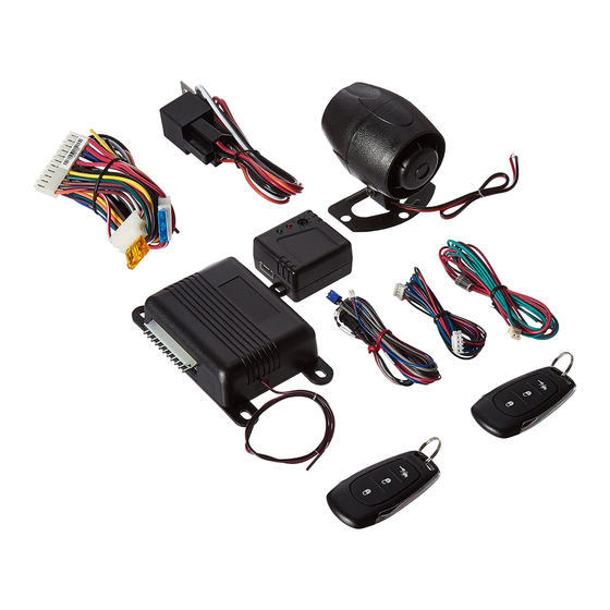
Wire Harness Quick View
Installation Of Components
11 Pin Main Wire Harness
2 Pin LED/Valet Connector
3 Pin Door Lock Connector & Wiring
Completing Your Installation
Dome Delay Learn Procedure
Final Steps Wire Dressing And Operation Explanation
Programming Transmitters
Programming Alarm Feature Bank 2
Circuit Wiring Layout
PATENTED: www.voxxintl.com/company/patents
Page 1
Model APS-25E
Installation Manual
Remote Control Vehicle
Security System
Page 2
Page 3
Page 4
Page 4-6
Page 6
Page 6
Page 6
Page 6
Page 6
Page 7
Page 7
Page 7
Page 8
128-9322
1/8
Advertisement
Table of Contents

Related Manuals for Prestige APS-25E


Summary of Contents for Prestige APS-25E
-
Page 1: Security System
Model APS-25E Installation Manual Remote Control Vehicle Security System Table Of Content: Before You Begin Page 2 Wire Harness Quick View Page 3 Installation Of Components Page 4 11 Pin Main Wire Harness Page 4-6 2 Pin LED/Valet Connector Page 6 3 Pin Door Lock Connector &... -
Page 2: Before You Begin
Before You Begin PROFESSIONAL INSTALLATION IS STRONGLY RECOMMENDED Roll down window to avoid locking the keys in the vehicle during installation. Avoid mounting components or routing wires near hot surfaces or near moving parts like the steering wheel as it may prevent proper operation of the vehicle. Tape or loom wires under the hood and dash for protection as well appearance. - Page 3 11 Pin Main Wiring Harness Part # 1122910 1 WHITE (+) Parking Light Output 15A Max 2 RED (+) 12 Volt Input Parking Lts 3 DARK BLUE Channel 3 Trunk Output (-) 300mA 4 WHITE/BLACK + 12 Volts Siren Output 5 RED/WHITE + 12 Volt Module Feed (See Red) 6 BLACK...
- Page 4 INSTALLATION OF MAJOR COMPONENTS: CONTROL MODULE: P/N 1365419 Select a mounting location inside the passenger compartment (up behind the dash) and secure using two screws provided. The control module can also be secured in place using cable ties. Do not mount the control module in the engine compartment, as it is not waterproof. You should also avoid mounting the unit directly onto factory installed electronic components.
- Page 5 CAUTION: Connecting the dark blue wire to the high current switched output of trunk release circuits or some remote starter trigger inputs, will damage the control module. Connect the dark blue wire to terminal 86 of the MRLY accessory relay (or equivalent 30 A automotive relay) and wire the remaining relay contacts to perform the selected function of channel 2.
- Page 6 GRAY/BLACK 2 PIN (blue) & RED/BLUE 2 PIN (white) CONNECTORS LED/VALET SWITCH Part # PRLED If you have not done so already, route the two 2 conductor, blue & white connectors from the previously installed combination LED Valet switch to the alarm control module and plug both connectors into their mating connectors on the end of the module.
- Page 7 CAUTION: Setting the sensitivity too high can cause false alarms due to noise vibrations from passing trucks and heavy equipment. To decrease sensitivity, turn the adjustment screw counter clockwise. Wire Dressing: Always wrap the alarm wires in convoluted tubing, or with a spiral wrap of electrical tape. Secure these looms along the routing using cable ties.
- Page 8 Pushbutton LED Assembly To Shock Sensor Red (+) Black (Ground) Green (Full Trigger) Blue (Pre Detect) Antenna Wire, Route As High Red = (-) Lock (+) Unlock As Possible And Away From Green = (+) Lock (-) Unlock Green Other Electronic Modules For Best Range APS25E Control Module 12 VDC Supply White (+) Parking Light Relay Output...
Need help?
Do you have a question about the APS-25E and is the answer not in the manual?
Questions and answers